We're assembling the first unit that incooporates all upgrades including the QPD tilt and here are minor problems we've stumbled upon. (No ISS array unit with an upgrade to tilt the QPD (E1400231) has been assembled before as far as I see and nobody seems to have cared to update all drawings.)
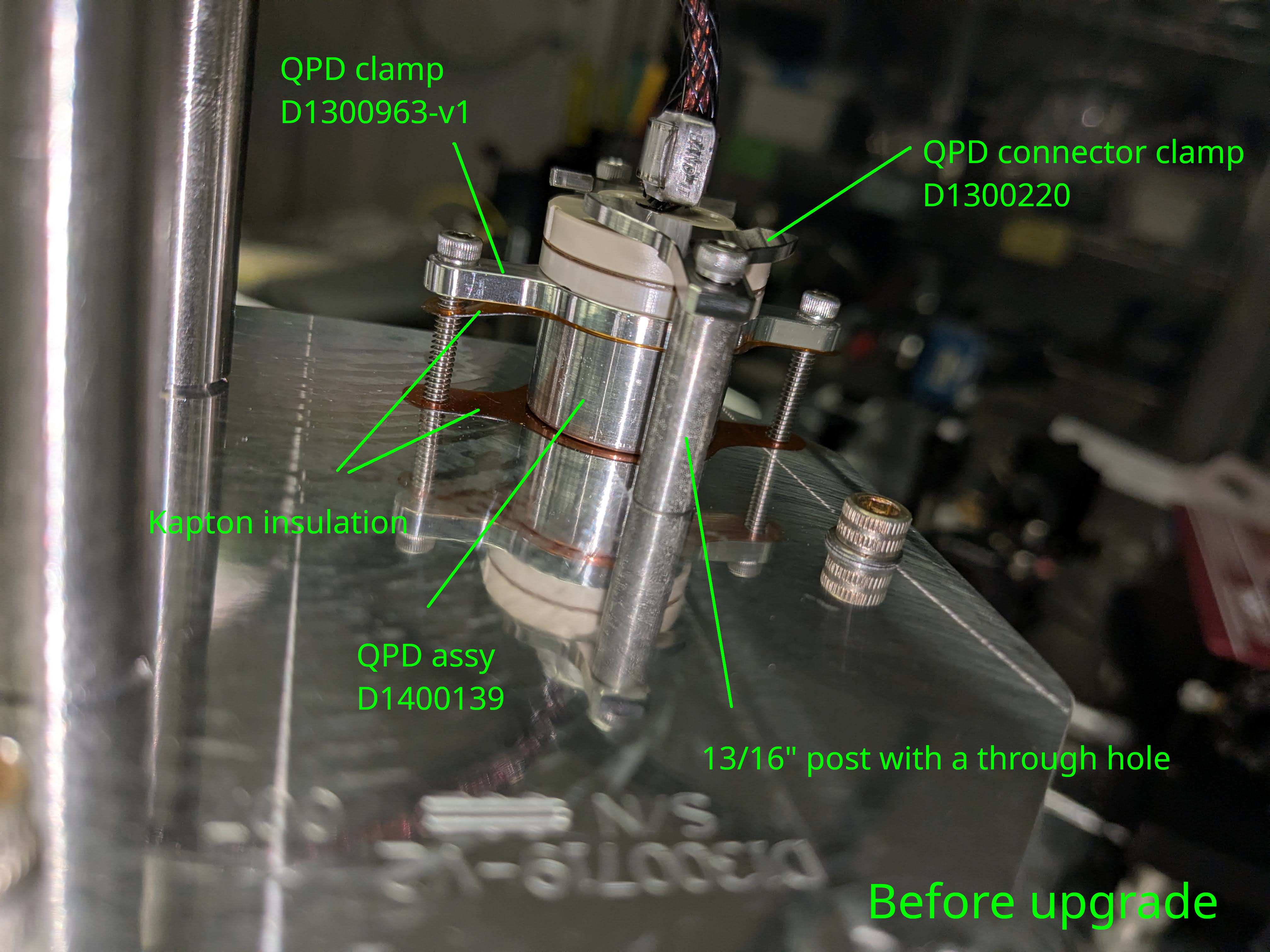
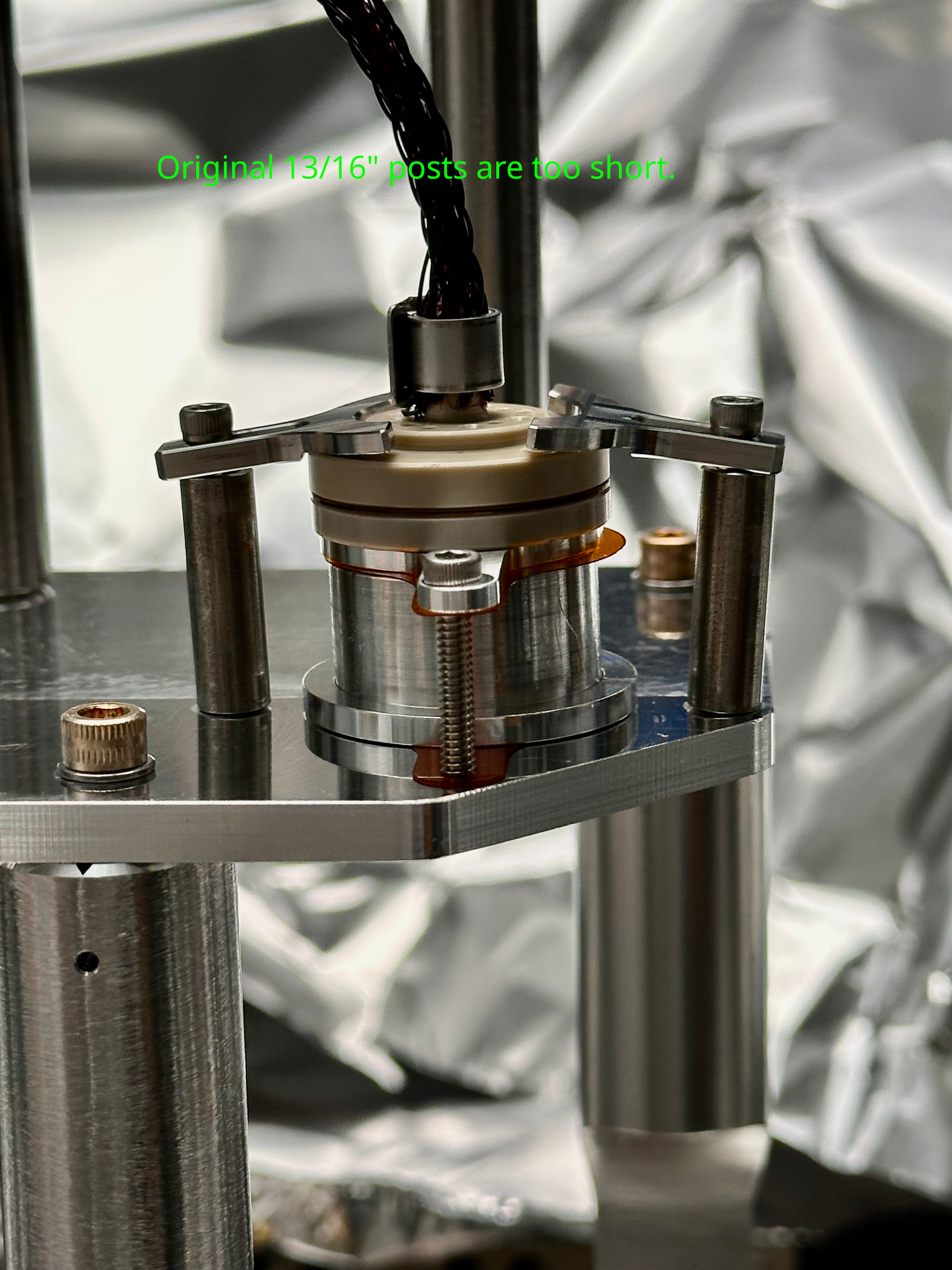
First picture is an example of the QPD before upgrade. QPD assembly (D1400139) and the cable connector assembly (D1300222) are mounted on the QPD platform by the QPD clamp plate (D1300963-v1, an older version) and a pair of split QPD connector clamps (d1300220). Two pieces of kapton insulation sheets are protecting the QPD assy from getting short-circuited to the platform.
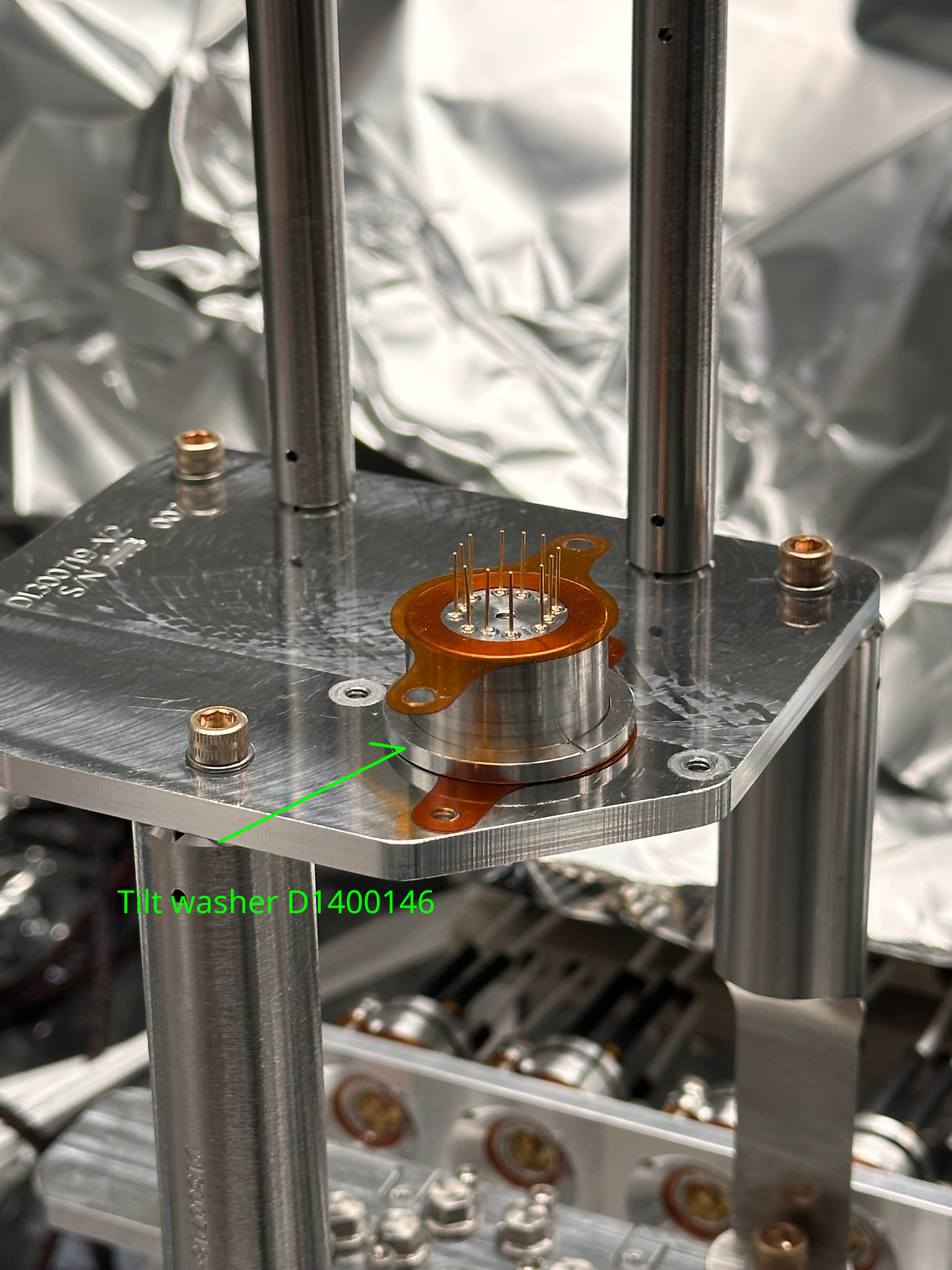
After the upgrade, the QPD assy sits on top of a tilt washer (D1400146, called beveled C-bore washer) that tilts the QPD by 1.41deg in a plane that divides YAW and PIT plane by 45 degrees (2nd picture). The bottom kapton will go between the washer and the QPD platform plate.
Problem 1: Insulation between the QPD clamp and the QPD pins is a bit sketchy.
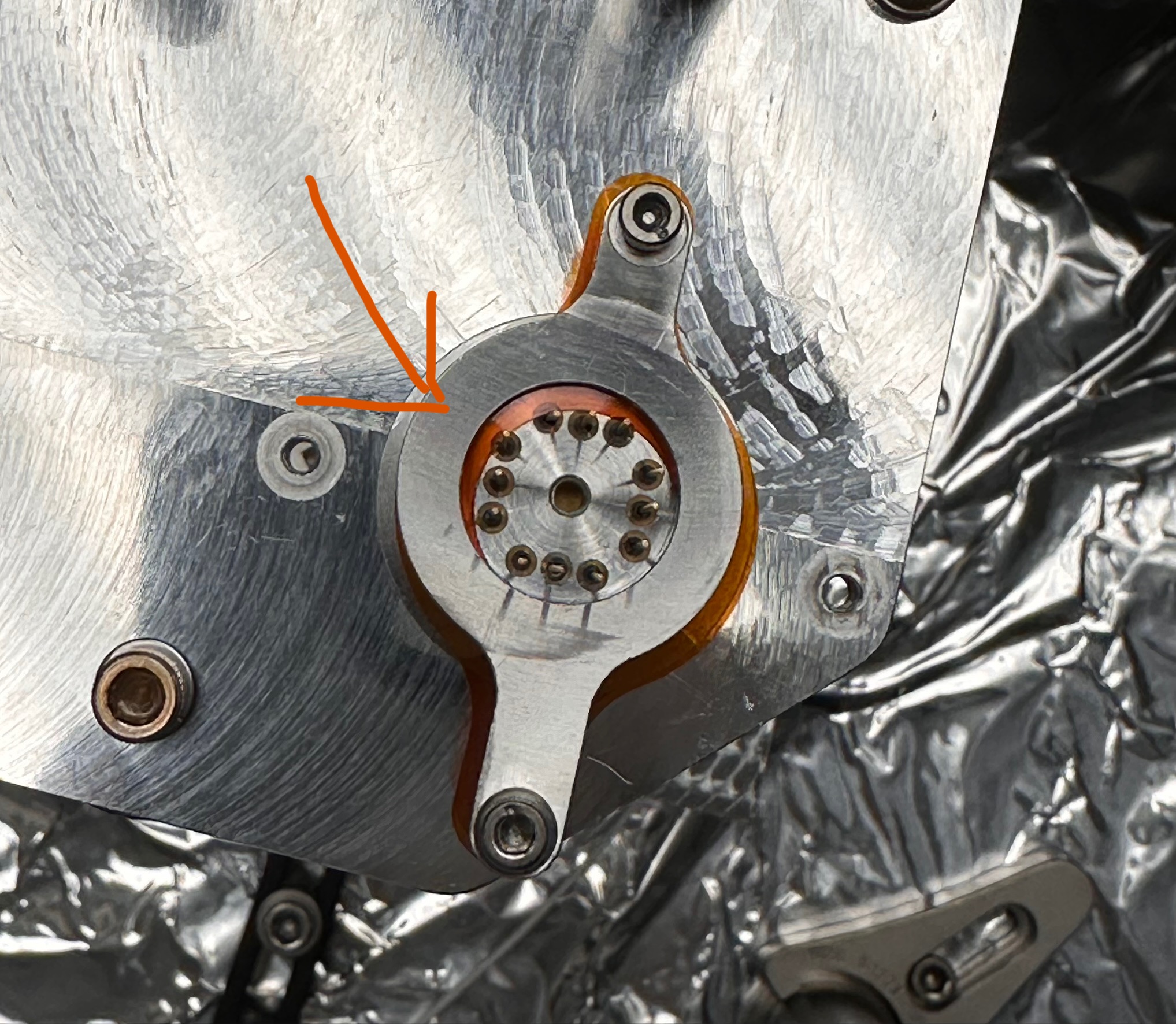
Titled QPD means that the bottom of the QPD assy is shifted significantly in YAW and PIT. A new asymmetric QPD clamp plate with tilted seating for the screws (D1300963-v2) has been manufactured to accommodate that. But we have no record of updated kapton insulators, so the center of the clamp bore doesn't agree with the kapton (3rd picture, note that the QPD rotation is incorrect in this picture, which had to be fixed when connecting the cable). Since the tilt washer is not captured by anything (it's just sandwiched between the clamp and the platform plate), it's not impossible to shift the QPD assy such that some of the QPD pins will be grounded to the clamp and thus to the QPD platform plate.
You must check that there's no electrical connection between the QPD assy and the platform each time you adjust the QPD position in the lab.
Problem 2: New QPD connector clamp posts are too long, old ones are too short.
Old posts for the QPD connector are 13/16" long, which is too short for the upgrade because of the tilt washer, see 4th picture where things are in a strange balance. It seems as if it's working OK, but you can wiggle the post a bit so the post slides laterally relative to the clamp and/or the platform, it settles to a different angle and suddnly things become loose. To avoid that, you tighten the screws so hard that they start bending (which may be already starting to happen in this picture).
Also, because the clamp positions are 45 degrees away from the direction of tilt, one clamp goes higher than the other.
To address these, somebody procured 1" and 15/16" posts years ago, but they're just too tall to the point where the clamps are loose. If anything, what we need are probably something like 27/32" and 7/8" (maybe 7/8" works for both).
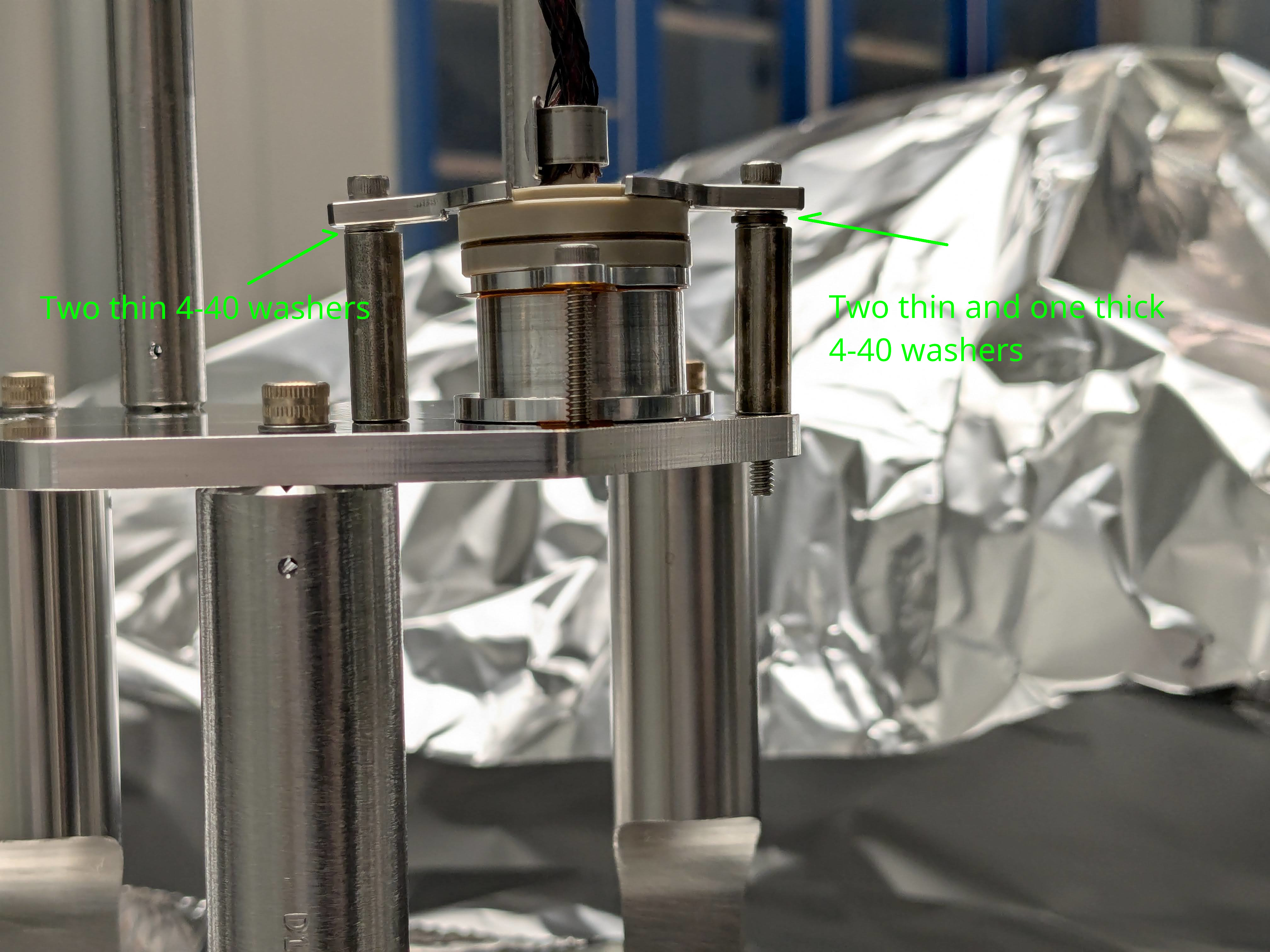
We ended up using older 13/16" posts, but added washers. Two thin washers for the shorter clamp, two thin plus one thick for the taller one (5th picture). This works OK. Shorter screw is the original, longer screw was too long but it works.
Problem 3: It's easy to set the rotation of the QPD wrong.
When retrofitting the tilt washer and the newer QPD clamp plate, you must do the following.
- Completely loosen the connector clamps and the QPD clamp to remove the QPD/connector assy as one unit.
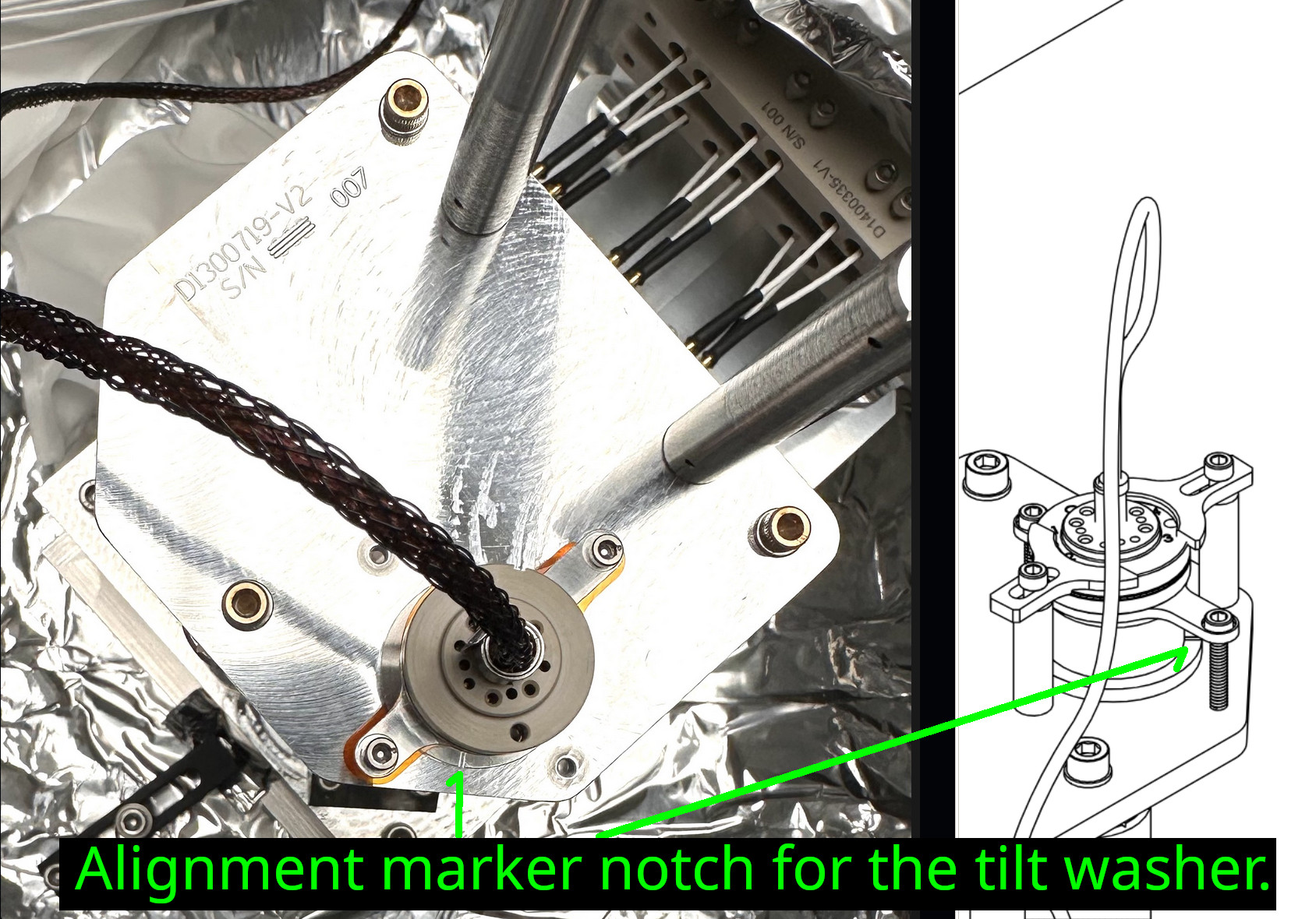
- Put the tilt washer on top of the kapton insulation sheet at the bottom. The notch mark on the washer must be pointing the 45deg edge of the platform plate (D1300719-v2), see the 6th picture.
- Separate the cable connector from the QPD to free the now-obsolete QPD clamp (-v1) that is captured between the QPD and the connector. I inserted a razor blade between the connector and the QPD assy and pried.
- Put the assymmetric QPD clamp (-v2) on the top kapton insulation, paying attention to the direction of the new clamp using the 3rd picture as the reference.
- Make sure that the rotation of the QPD assy is the same as before because the pins of the QPD are not symmetric. There's no physical mark on the QPD assy itself.
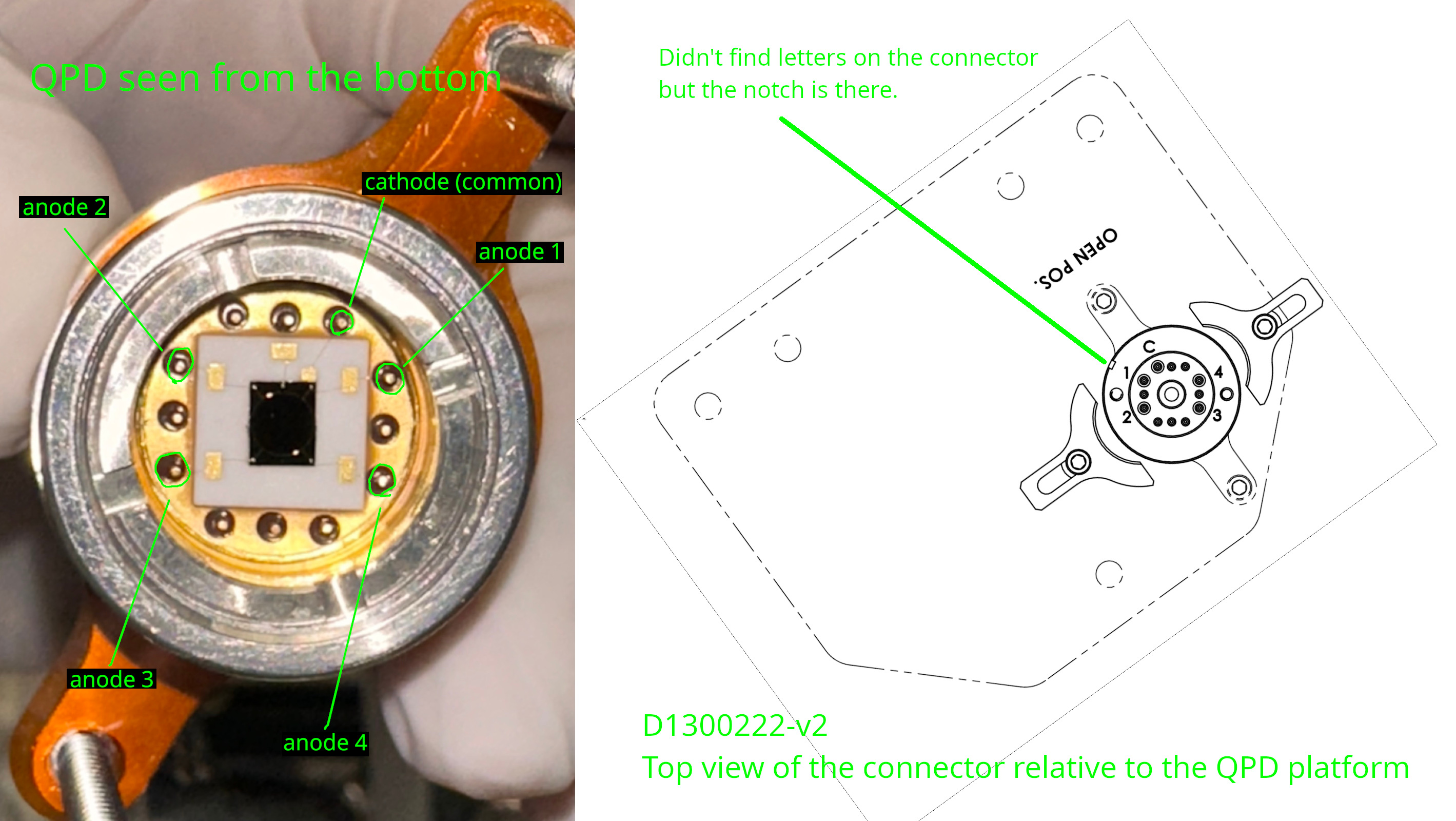
- If you're unsure, rotate the QPD assy such that the QPD pins will go to the right sockets on the connector using picture 7. Remember that QPD surface faces the platform down and the drawing of the connector is viewed from the top.
- After checking it several times, tighten the QPD clamp.
- Put the connector on. Again use picture 7 to put it on at the correct angle.
- After checking it several times, tighten the connector clamps.
I screwed up and put the QPD on the connector at a wrong angle. It's easy to catch the error because no quadrant responds to the laser, but it's better not to make a mistake in the first place. It will help if the QPD assy barrel is marked at the cathode-anode1 corner.
It seems that D1300222 and D1101059 must be updated. Systems people please have a look.
D1300222: A tilt washer (D1400146), a new QPD clamp (D1300963-v2) and two sheets of kapton insulation are missing. Spacers are longer than 13/16".
D1101059: Explicitly state that part #28 (D1300963, QPD clamp) must be D1300963-v2.
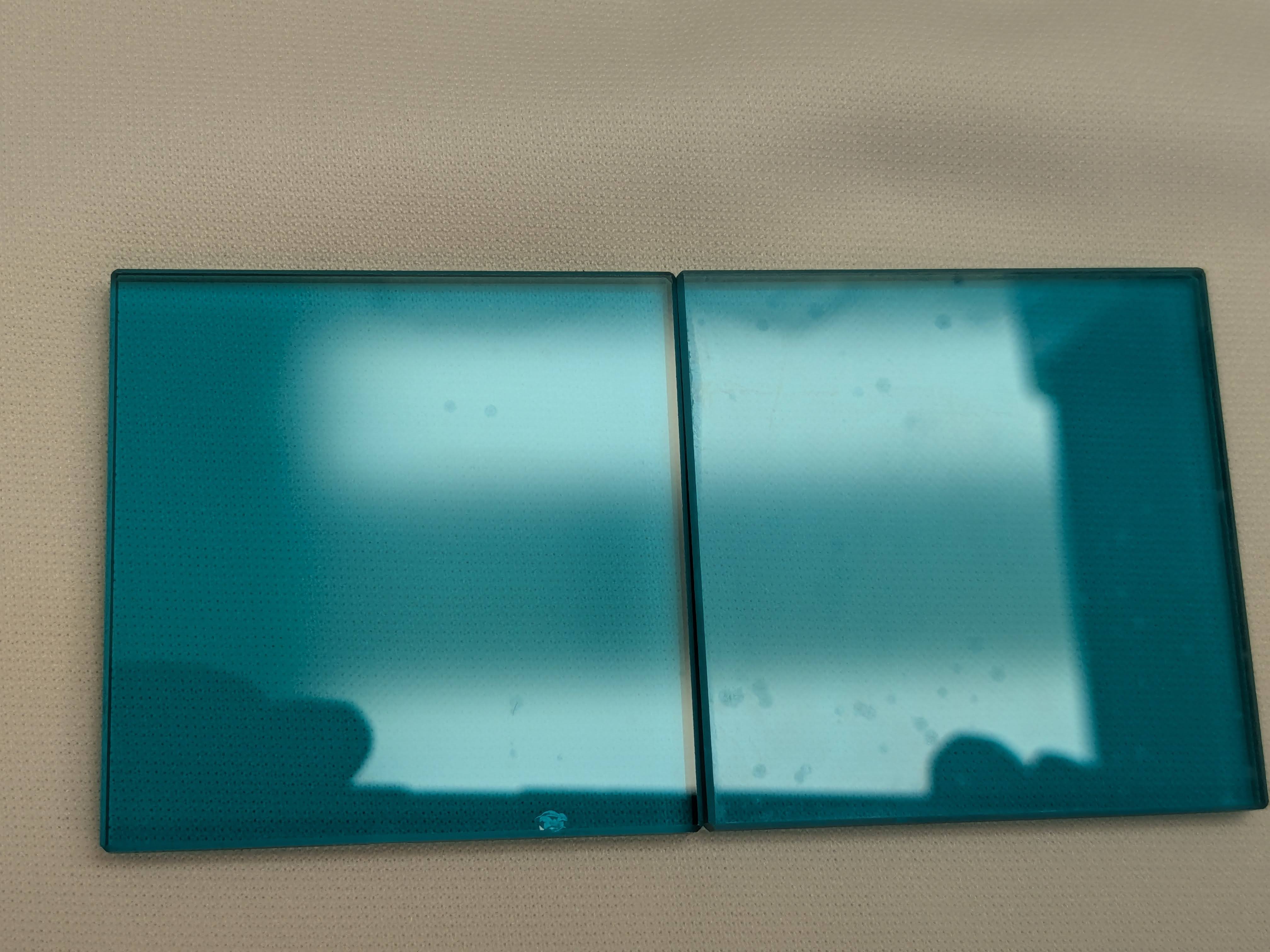
I installed the beam dumps (which are two plates of filter glass, probably from Schott?) for the array after cleaning them according to E2100057.
There are marks that look like water spots and/or some fog that couldn't be removed by repeated drag wiping with methanol (see picture).
After installation, I found that these plates are very loosely captured between two metal plates, see the video, this seems to be by design. I don't like it but the same design has been working in chamber for years.