Jennie W, Rahul, Keita
This is just a summary of our work over the last two days trying to repeat the alignment coupling measurements for the replacement ISS array unit (D1101059, unit S1202965). The reason we need to repeat these is because we have now uograded the washer and clamp plate in QPD assembly. See Keita's previous alog for details.
Thursday
First we changed input alignment to get roughly 4 V on each PD in the array, this is acheived by inserting the larger iris and using the two steering mirrors (M2 closest to the array, M1 further towards the laser) to change the input alignment of the auxiliary laser into the unit.
As we have tilted the QPD by adding the new components we need to re-align the QPD to centre the beam (which is split off from the main beam entering the unit by the beam splitter on the elevator assembly which sits at one corner of the ISS array unit).
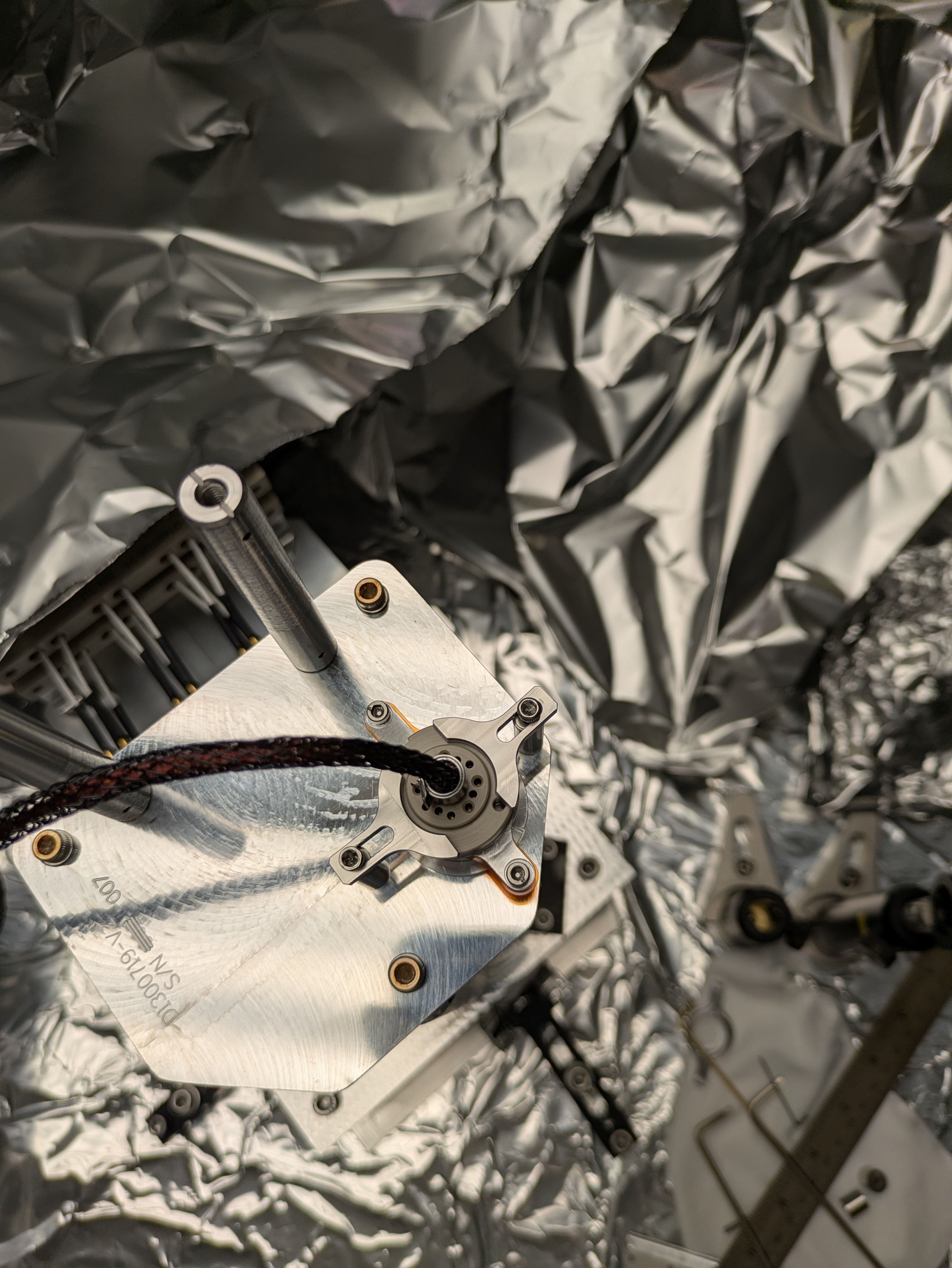
Then we unscrewed the four screws holding the QPD down (see image) and tried to move the QPD to minimise the coupling from yaw motion if the input beam to pitch. We only managed to minimise pitch coupling and couldn't get it centred on qpd in yaw as the whole QPD unit moves a lot when not screwed down.
We screwed down the QPD but it was still off in yaw by a lot (see image).
As we were adjusting the input alignment mirror to check the coupling I managed to lost the input alignment to the array.
Friday
Today Keita brought the input alignment back by using the beam viewer to check the position on the diodes while changing M2. Then we saw about 3.5-4V on each of the PDs in the array. Next we only undid the two lower screws on the QPD (these hold the QPD unit itself clamped to the platform it sits on, the two upper screws hold in the connector to the back of the QPD and these were only slighly loosened). Keita moved around the unit till the QPD readout showed we were near centred and then we screwed down the unit. It moves alignment while being screwed down probably because of the angle of the QPD relative to the clamp.
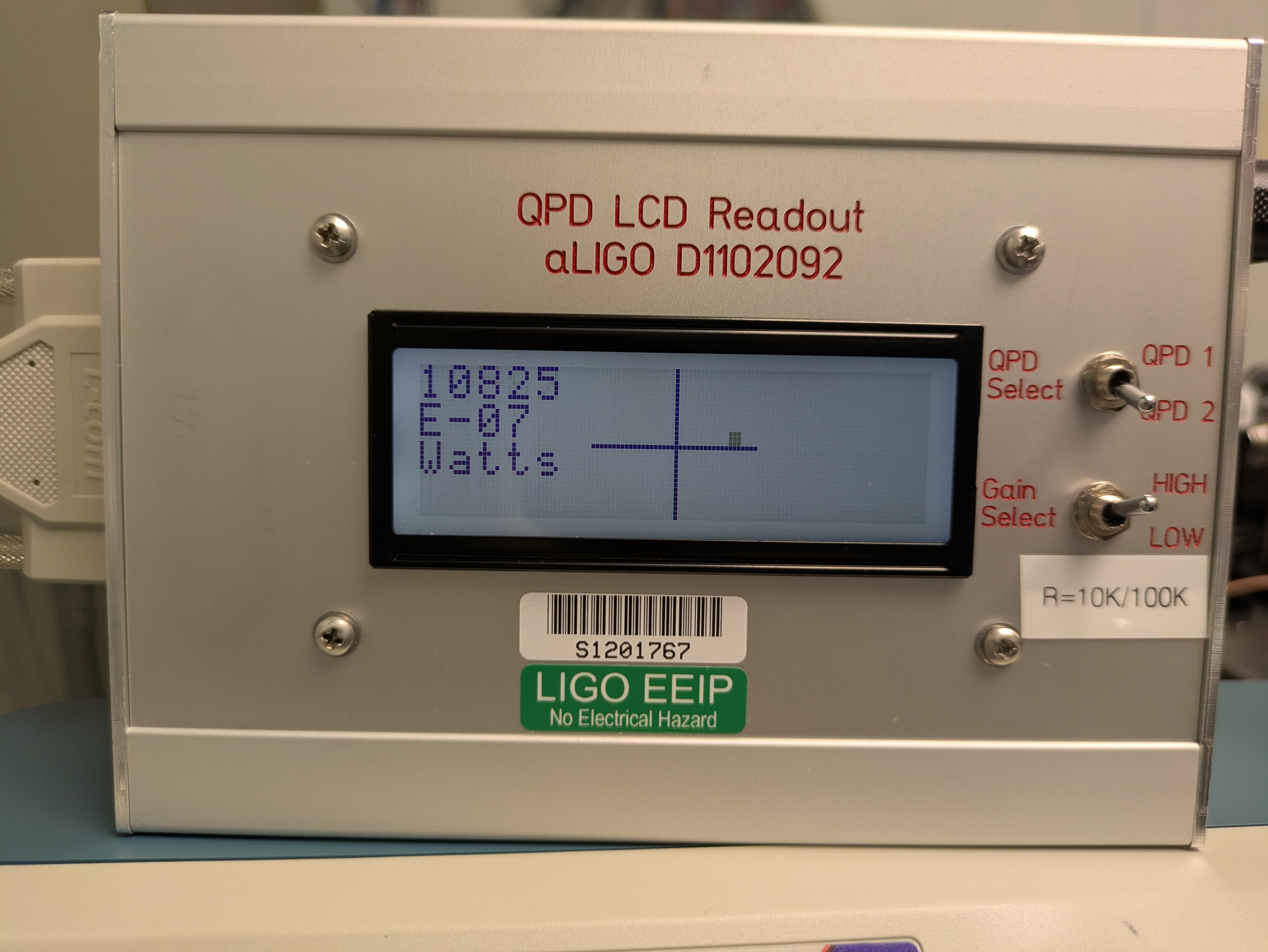
For this alignment we used the QPD amplifier unit that gives a live visual readout of the centering.
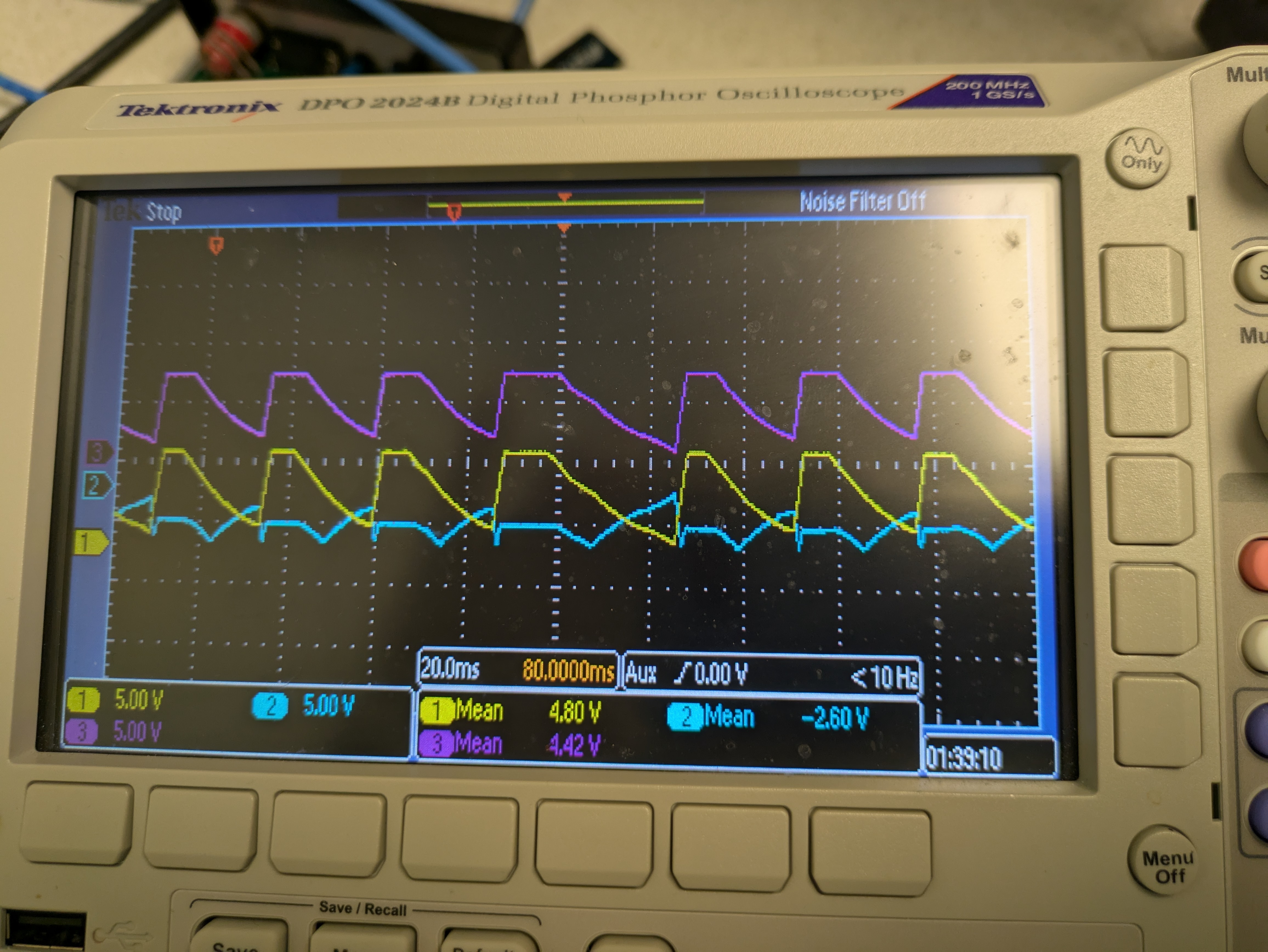
We also have the option of using another amplifier that gives the QPD X, Y and SUM channels so we can read them on an oscilloscope but these had some weird saw tooth noise on them (see image from Thursday). Keita then discovered that we were using the wrong cable (too low a current rating) for this amplifier, we searched for the correct one but could not find it. We will get back to this on Monday.
Summary: We think we now have the QPD in a good place relative to the PD array as yaw and pitch are fairly decoupled, but maybe the angle of the QPD in rotation is still slightly off as the P and Y motion of the beam are still slightly off from the QPD quadrants. We need a new cable for the ON-TRAK amplifier.