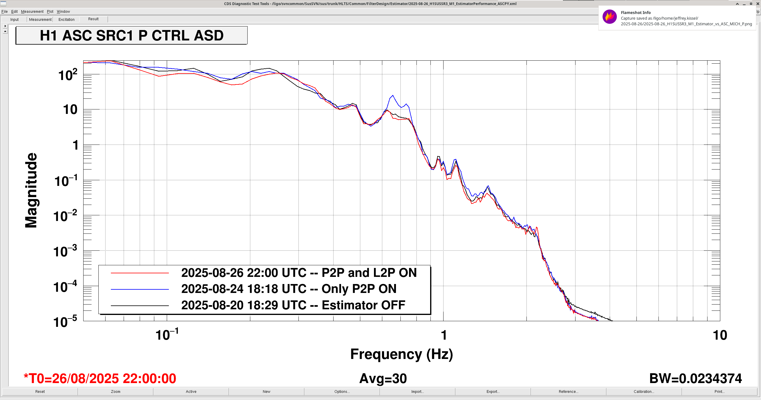
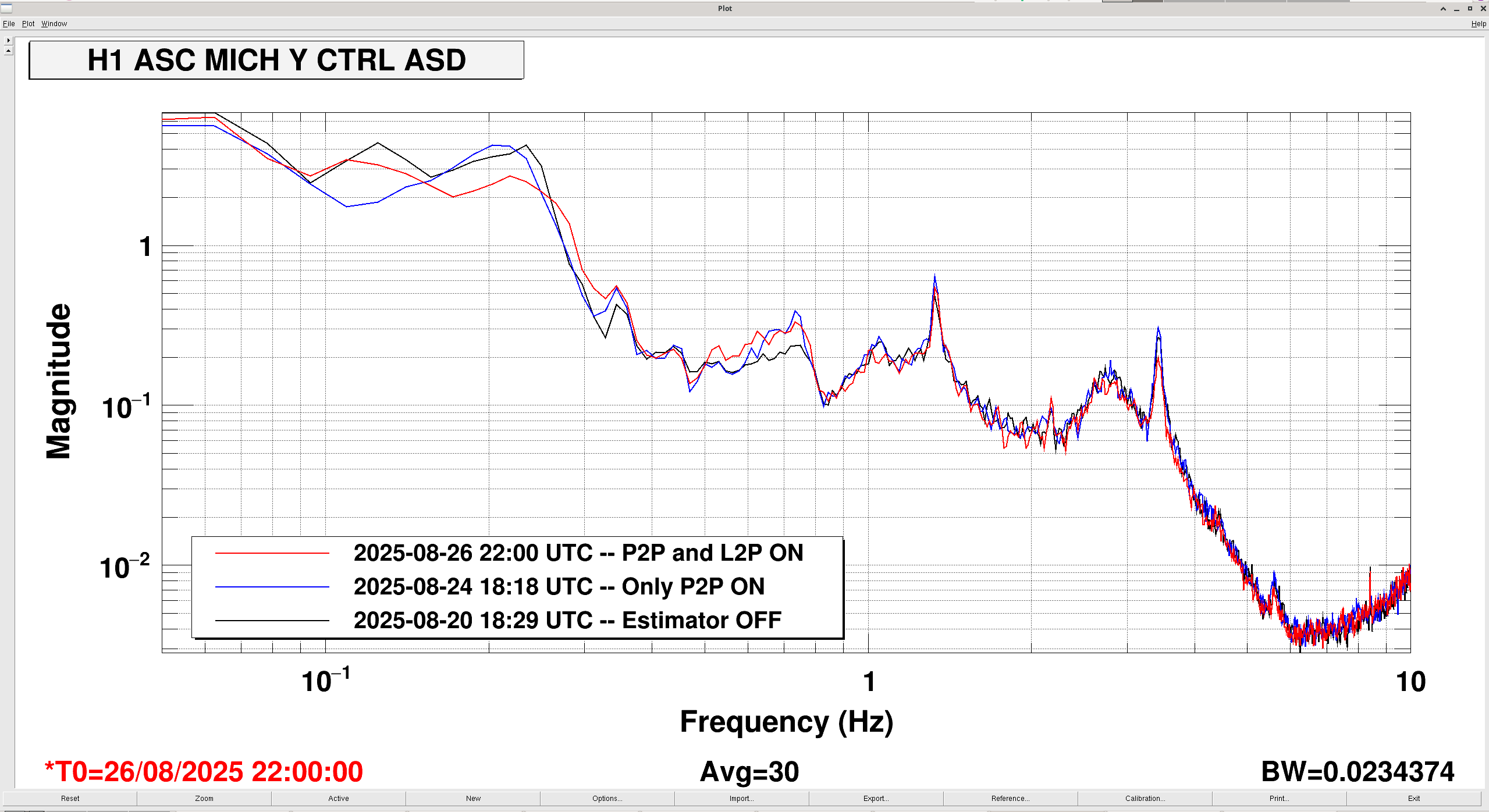
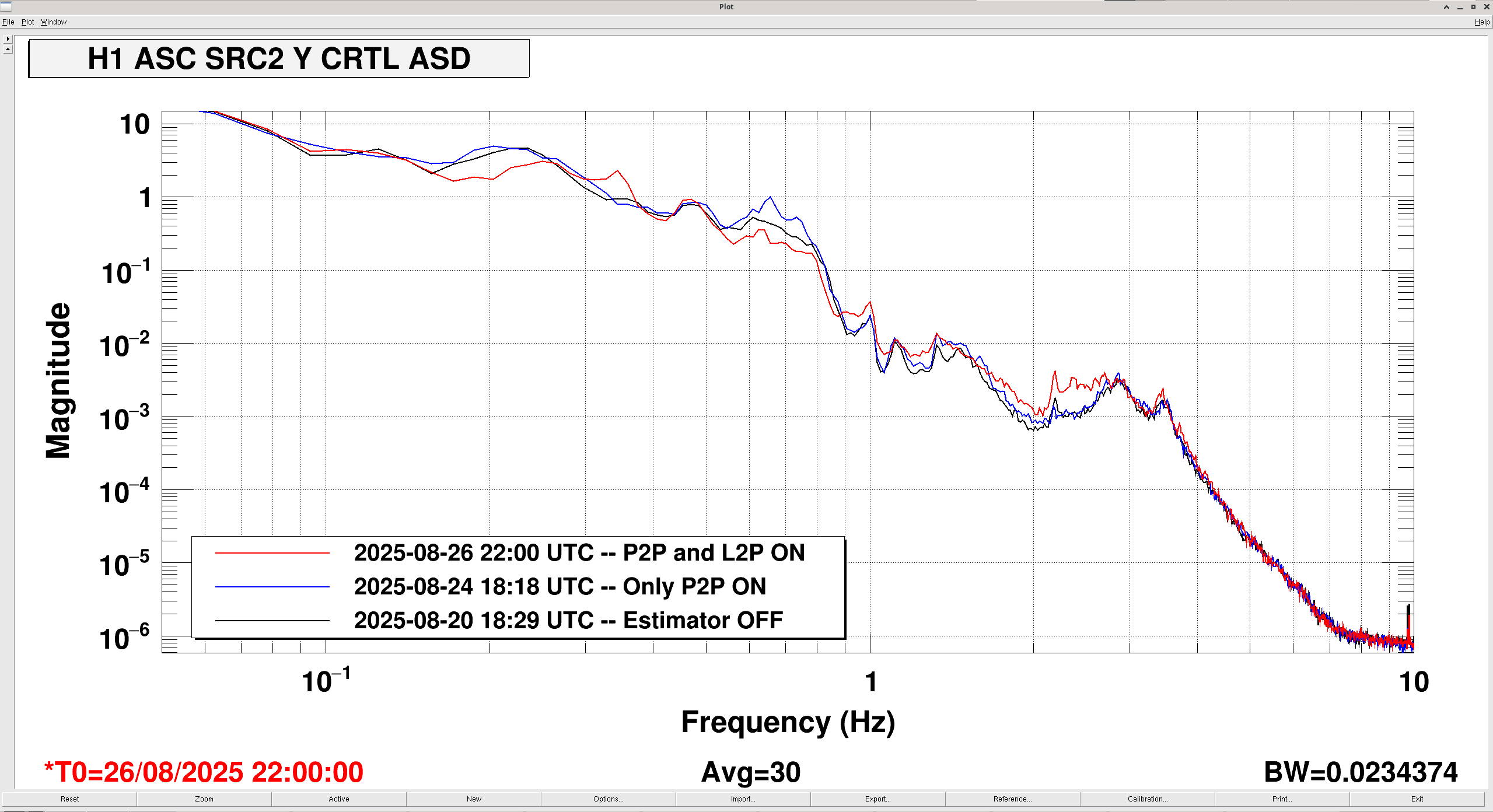
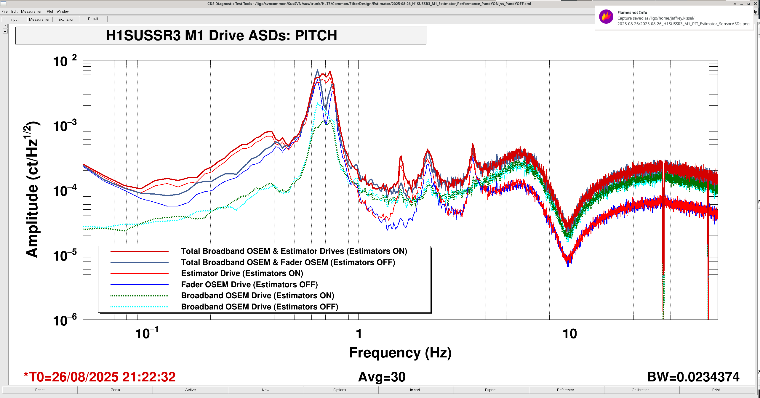
J. Kissel

After today's H1 SUS SR3 Pitch Estimator's inclusion of the Sus. Point L to M1 P feed forward from the HAM5 ISI GS13s (where we had mistakenly only installed Sus. Point P to M1 P) -- see LHO:86567, I now compare the times of ASC signals (using 0.02 Hz binwidth, 64 sec FFT chunks, 30 averages, and a Hanning window with 50% overlap):
    2025-08-20 18:29 UTC - Both P and Y Estimators are OFF
    2025-08-24 18:18 UTC - Both P and Y Estimators are ON, but for the P estimator, only the Sus. Point P to M1 P contribution is included in the GS13 FF
    2025-08-26 22:00 UTC - Both P and Y Estimators are ON, and for the P estimator, both P to P and L to P contributions are included in the GS13 FF.

I'm showing only the control signals, and only the ASC DOFs which are impacted by SR3: DHARD, MICH, SRC1, and SRC2; both pitch and yaw.

In All DOFs, the 0.64 and 0.75 Hz modes that had been made worse with only the P to P model of suspension point contribution have now been restored to no-estimator levels.
In some DOFs, the 1-10 Hz broadband motion is just barely improved, but enforces the conclusion that SR3 is only partially, if not 'not the dominate contribution' to the ASC signals.
Here's a fun one for you -- look at SRC2 Y CTRL -- and look at how much the SRC2 *yaw* motion has changed from including the *longitudinal* suspension point contribution to M1 *pitch* top mass. #ThrowsHandsInAir

But -- overall -- with the improvements and all design intent included -- the SR3 P and Y estimators slightly improve the ASC noise from 1 to 10 Hz. Great!

As Oli notes in LHO:86551 comparing all of these different configurations from totally different days and times is dubious. We'll get "official" versions of all of these ON vs. OFF configurations on Thursday 8/28.

I also attach the local estimator metrics for pitch described in LHO:86553, comparing "only Sus Point P to M1 P modeled contribution" against "P to P and L to P sus point to M1 contribution." That similarly shows that L to P contribution forms a good fraction of the signal needed for damping.


Great to see that the inclusion of the SUSpoint L to M1 P block makes a difference.
Unfortunately, the P2Y coupling is a wierd non-reciprocal coupling we were seeing on the measurements [See page 21 about the SR3 measurements from june after an OSEM calibration test]. The Pitch to Yaw transfer function is consistent with the conversion of pitch motion to observed yaw signals on the LF and RT OSEMs, this apparent motion gets turned into yaw feedback drive and creates the transfer function you see in the measurements linked.
Brian and I discussed it before and we had decided against adding a cross-term in the estimator to address it because it is both not well understood (at least we don't know why the LF and RT OSEMs see Pitch signals) , and because it is possible that we might only be able to address it if we commission the estimators in a fully serialized way, which would be even more time consuming for (probably) minimal benefit.
Depending on schedule, we can figure out if it is worth adding an M1 drive P to M1 Y estimator path, and probably commission a baby version of it with the measurements that Oli already took to see if it makes a difference.
I've confirmed in 86784 that the excess noise seen in the red trace between 1-3 Hz is not due to the SR3 Estimator having L2P compensation