J. Oberling, K. Kawabe
This afternoon we went into the PSL enclosure to inspect things after last week's power outage. We concentrated on the IOO side of the PSL table, downstream of the PMC. Our results:
We did a visual inspection with both the IR viewer and the IR-sensitive Nikon camera and did not find any obvious signs of damage on any of the optical surfaces we had access to; the only ones we couldn't see were the crystal surfaces inside the ISC EOM, we could see everything else. I looked at the optics between Amp2 and the PMC and everything there looked normal, no signs of anything amiss.
While the beam was not perfectly centered on every optic, we saw no clipping anywhere in the beam path. The irises after the bottom periscope mirror were not well centered, but they've been that way for a while so we didn't have a good reference for assessing alignment in that path (these irises were set after the O4 PSL upgrade, but there have been a couple of alignment shifts since then and the irises were not reset). For reference, the beam is in the -X direction on the HWP in the power control rotation stage and in the -Z direction (but centered horizontally) on the PZT mirror after the power control stage. We do have a good alignment reference on the ALS path (picked off through mirror IO_MB_M2, the mirror just before the ISC EOM), as those were set as part of the HAM1 realignment during this year's vent. By my eye the first iris looked a tiny bit off in yaw (-Y direction) and pitch (+Z direction), while the second iris looked perfectly centered. We found this odd, so Keita used the IR-sensitive camera to get a better angle on both irises and took some pictures. With the better angle the beam looked well centered in yaw and maybe a little off in pitch (+Z direction) on that first iris, so I think my eye was influenced by the angle from which I was viewing the iris. The second iris still looked very well centered. Edit to add: Since the ALS path alignment looks good, to me this signals that there was not an appreciable alignment shift as a result of the change in PMC temperature. If the PMC was the source of the alignment shift we would see it in both the main IFO and ALS paths. If there is a misalignment in the main IFO path, its source is not the PMC. Upon further reflection, a more accurate statement is: If the PMC is the source of an alignment shift, the shift is too small to be seen on the PSL table (but not necessarily too small to be seen by the IMC).
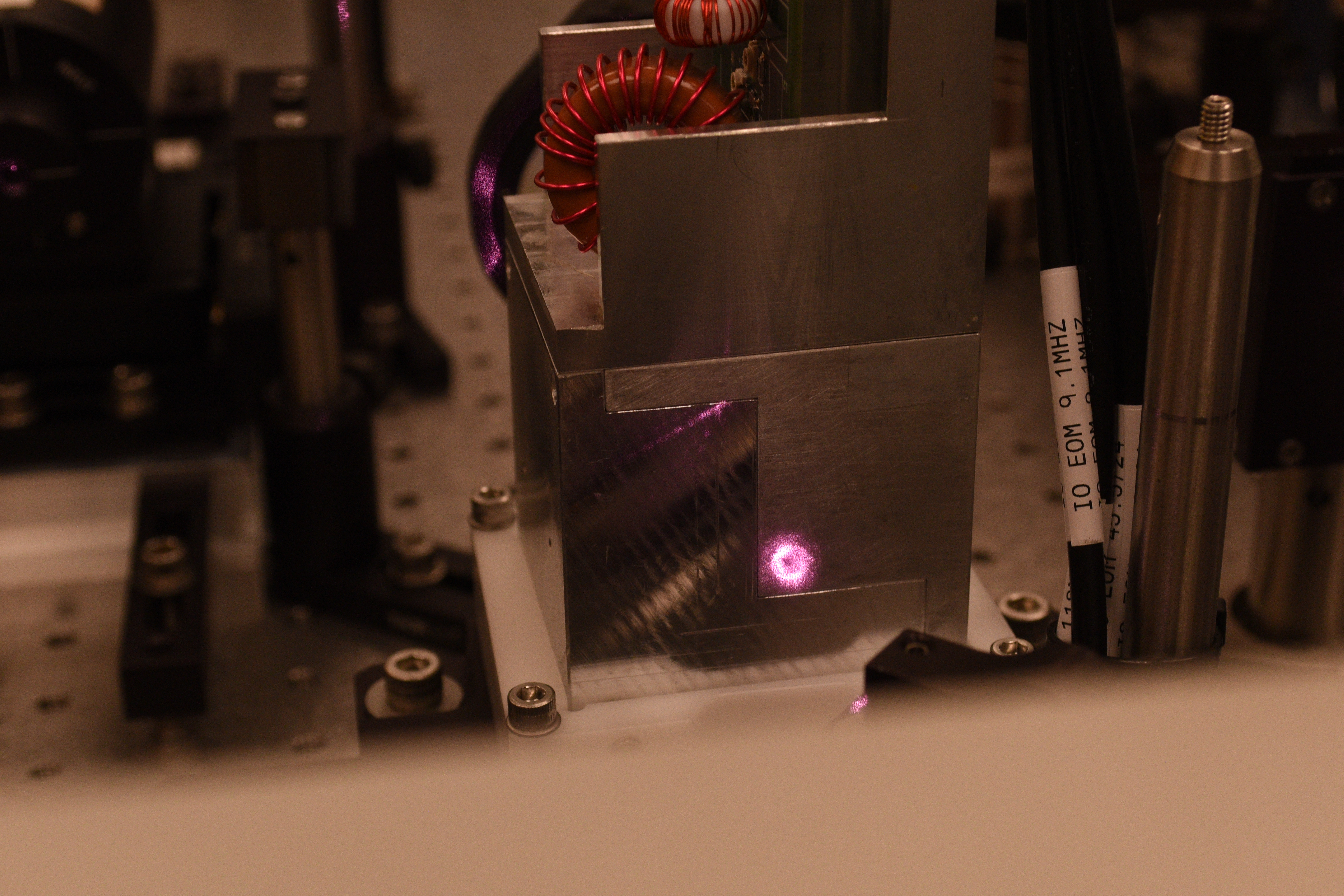
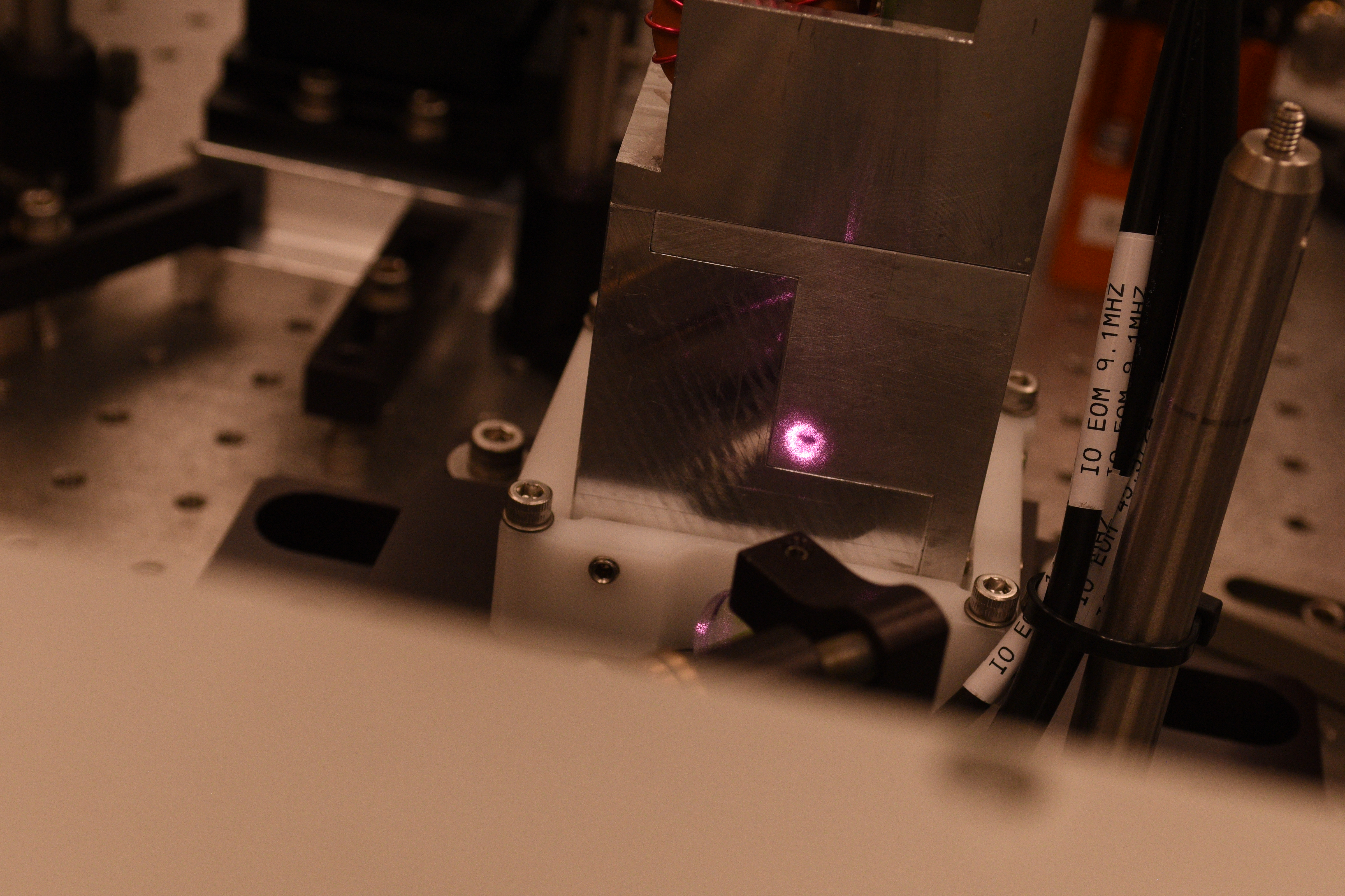
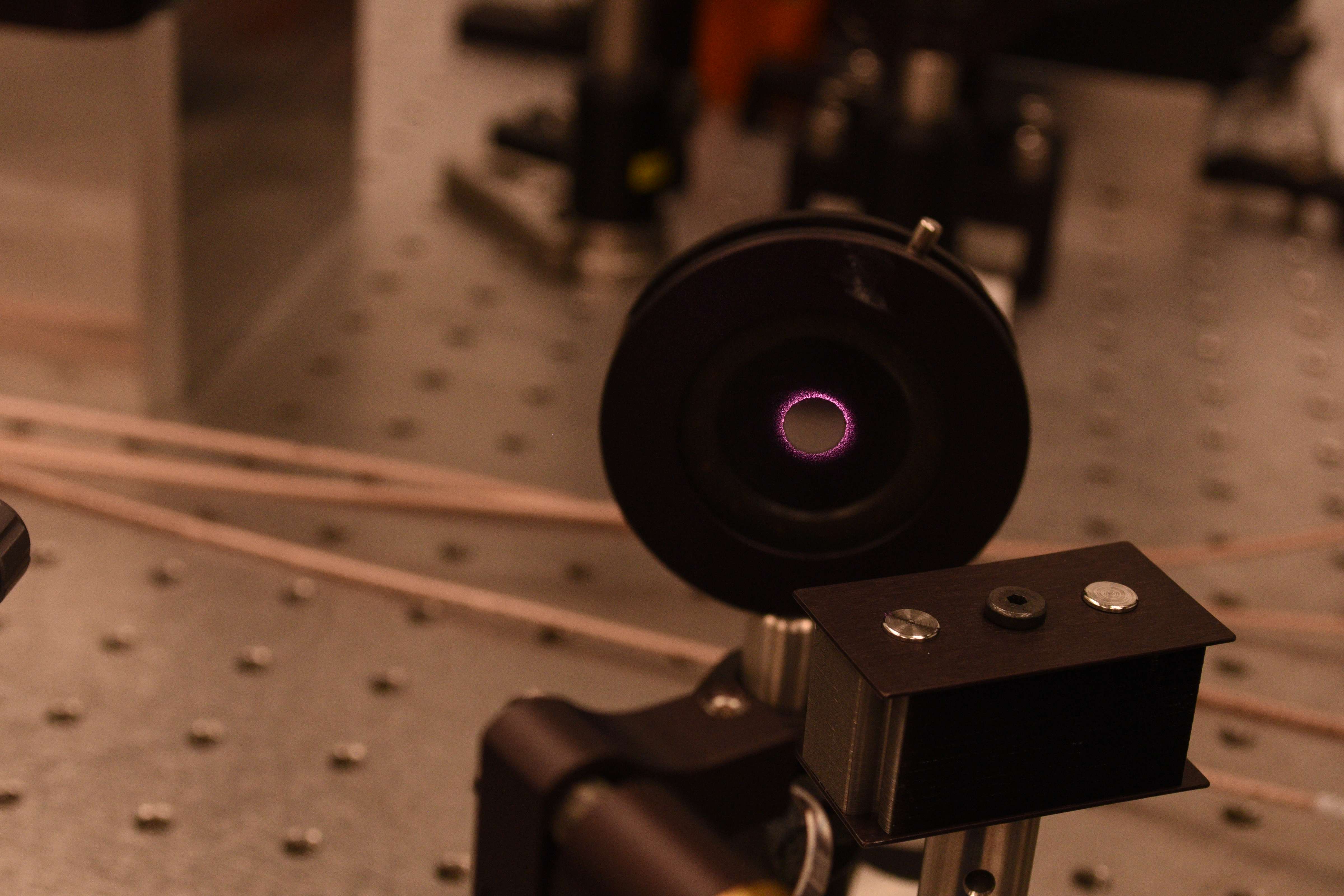
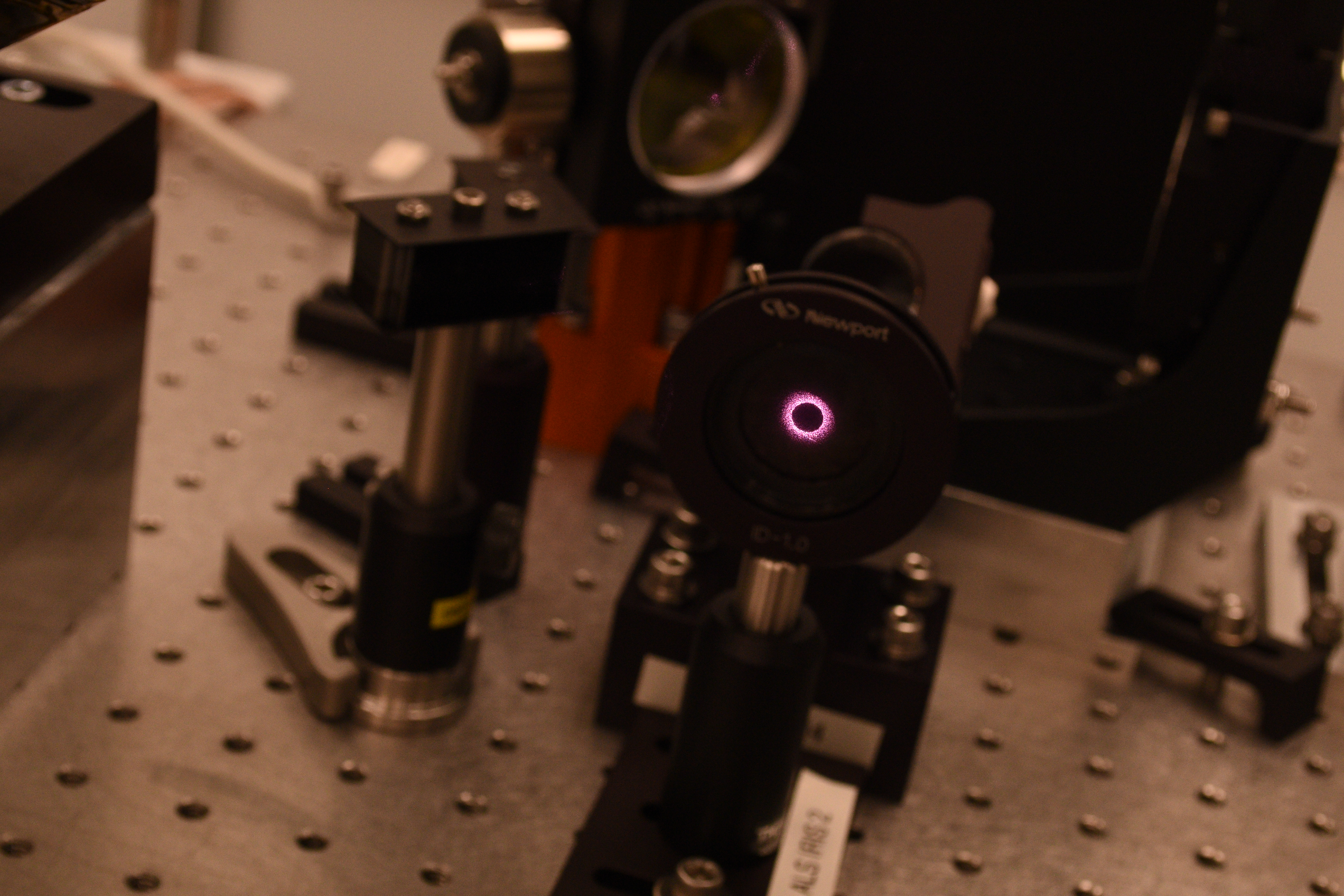
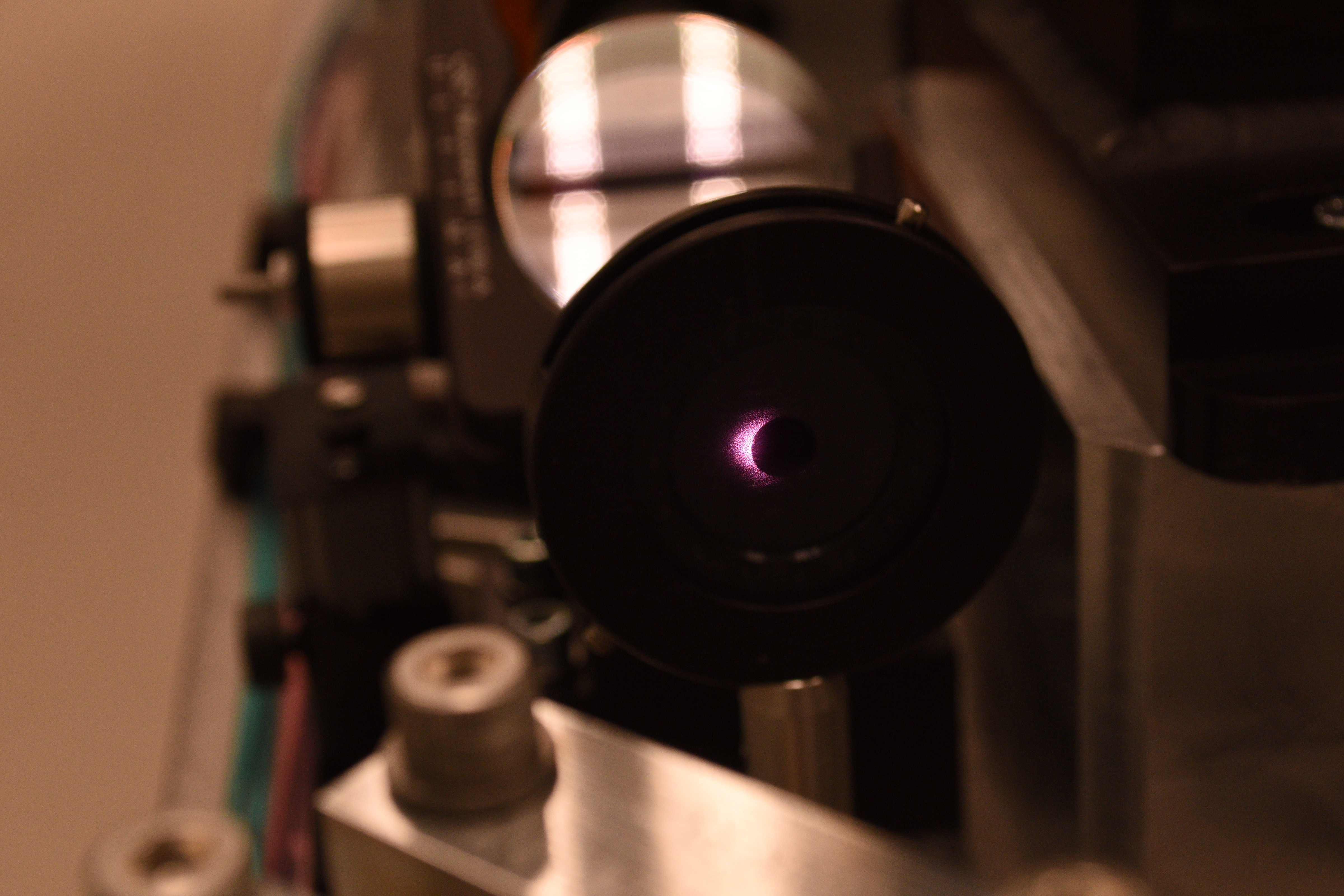
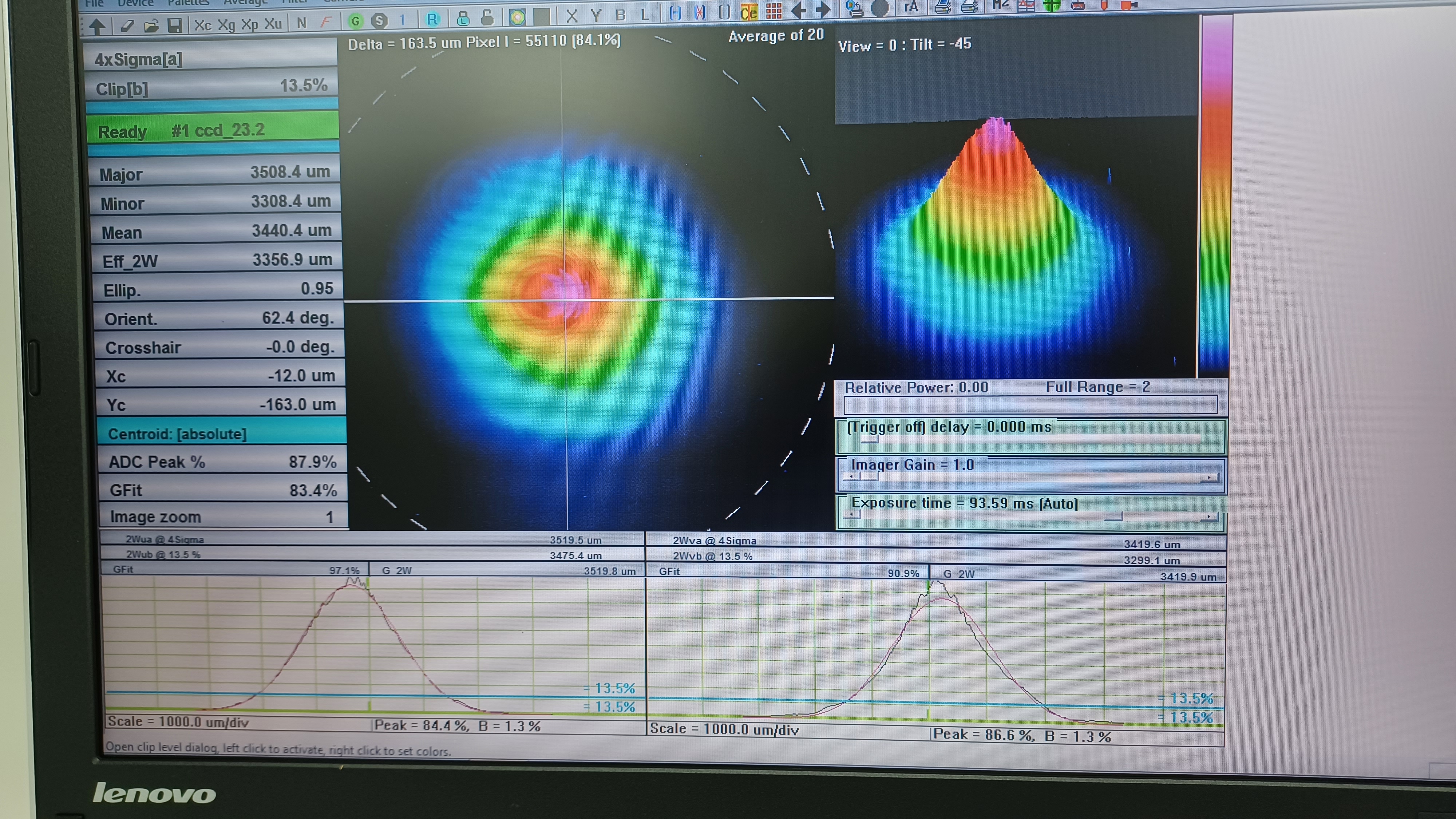
The other spot of note is the entrance aperture for the ISC EOM. It's really bright so it's hard to make a definitive determination, but it could be argued there's a very slight misalignment going into the ISC EOM. I couldn't make anything out with the IR viewer, but Keita's picture shows the typical ring around the aperture a little brighter on the left side versus the right. Despite this, there is no clipping in the beam, as we set up a WinCAM beam profiler to check.
The WinCAM was set behind IO_AB_L4, which is the lens immediately behind the bottom periscope mirror (this is the path that goes to the IMC_IN PD). The attached picture shows what the beam looks like there. No signs of clipping in the beam, so it's clearing all the apertures in the beam path. I recall doing a similar measurement at this spot several years ago, but a quick alog search yields nothing. I'll do a deeper dive tomorrow and add a comment should I find anything.
So to summarize, we saw no signs of damage to any visible optical surfaces. We saw no clear evidence of a misalignment in the beam; the ALS path looks good, and nothing in the main IFO path looks suspicious outside of the ISC EOM entrance aperture (a lack of good alignment irises makes this a little difficult to assess; once we get the IFO back to a good alignment we should reset those irises). We saw no clipping in the beam.
Keita has many pictures that he will post as a comment to this log.
For PSL table layout, see https://dcc.ligo.org/D1300348/.
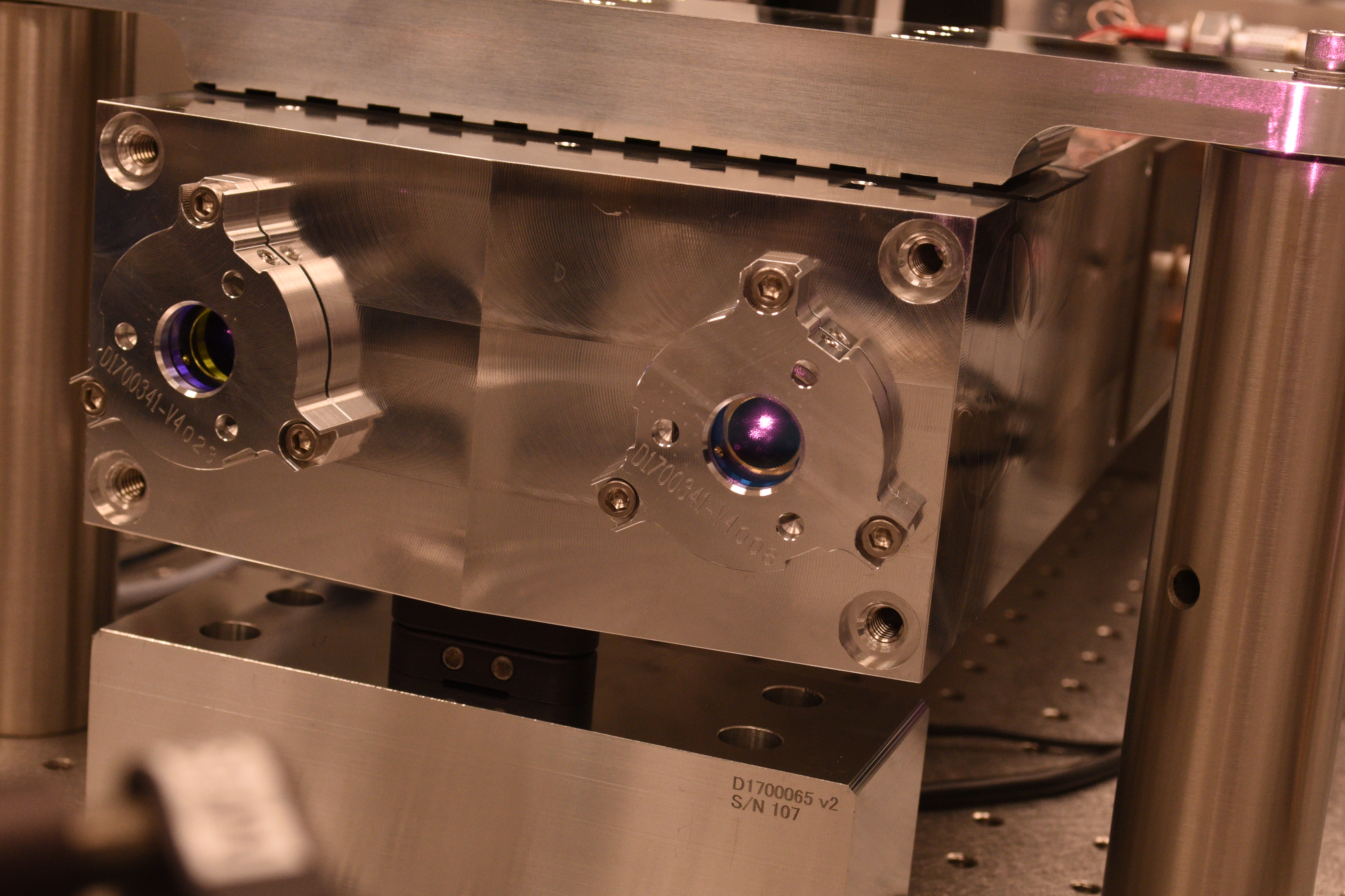
- Picture 1 and 2: PMC input coupler shows some scattering on the front surface as well as HR surface but nothing unusual. Same thing for the output coupler. (The output coupler clamp plate receives a ghost beam, Jason remembers that this was always the case.)
- Picture 3, 4 and 5: HWP (IO-MB-HWP1) and the polarizer for the manual power adjustment, the splitter for EOM-ALS: Not centered but far from clipping.
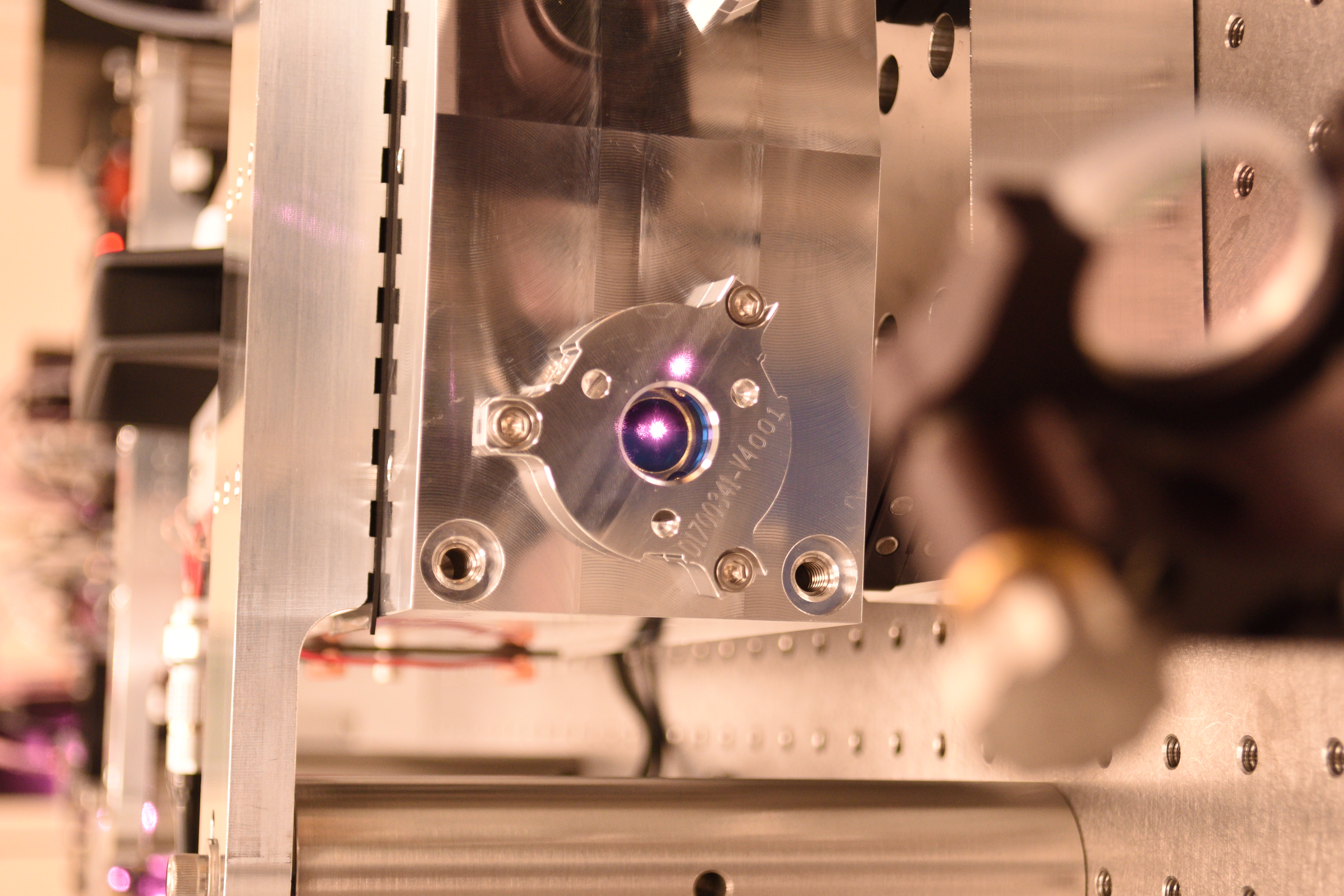
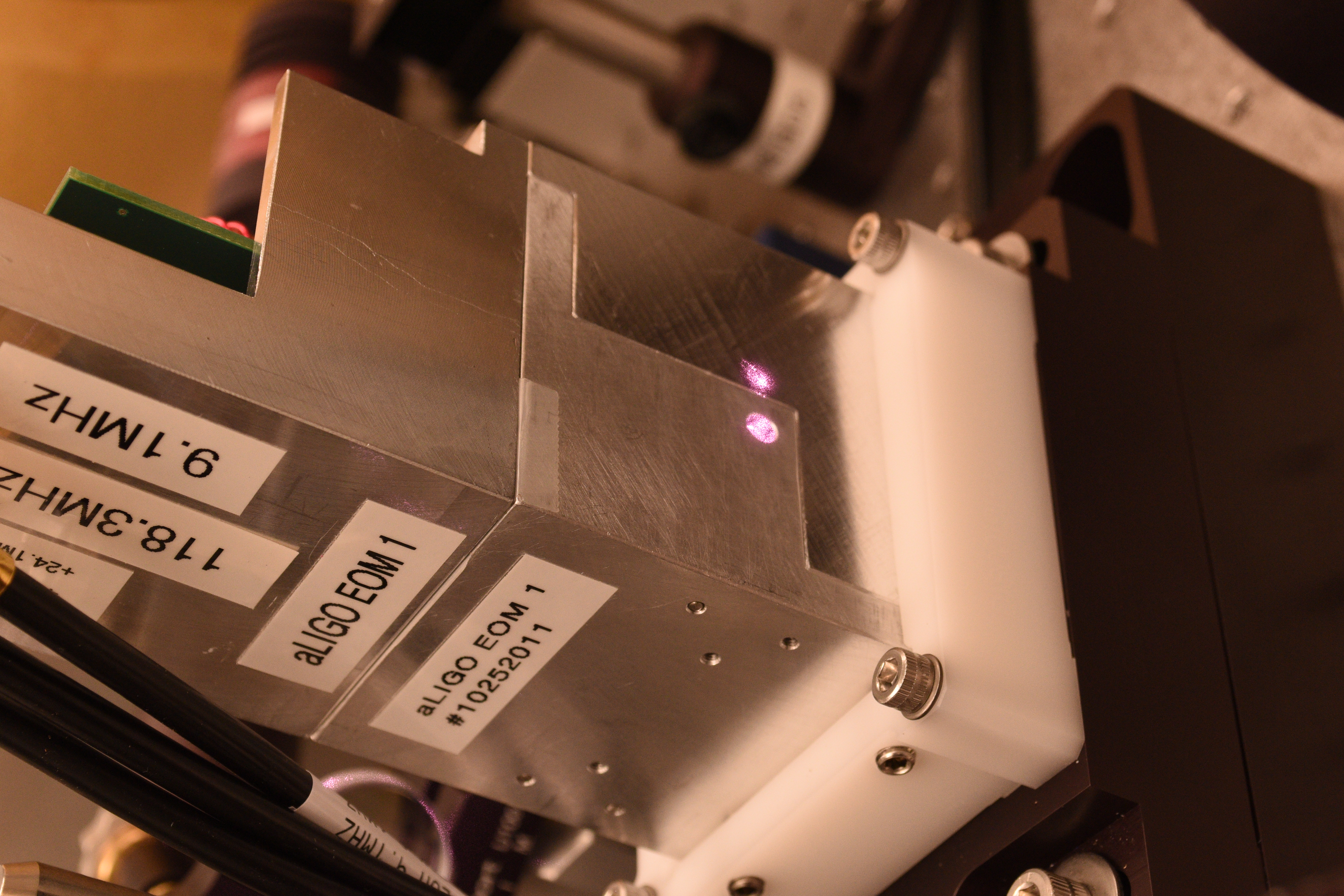
- Picture 6 and 7: EOM input looks a bit off-centered in YAW to the left, but not extraordinarily so. Pictured from different viewing positions to make sure that this is not some kind of photograph artifact.
- Picture 8: EOM output. Hard to say anything except that you can see a ghost beam on the EOM case to the right of the output aperture in this picture.
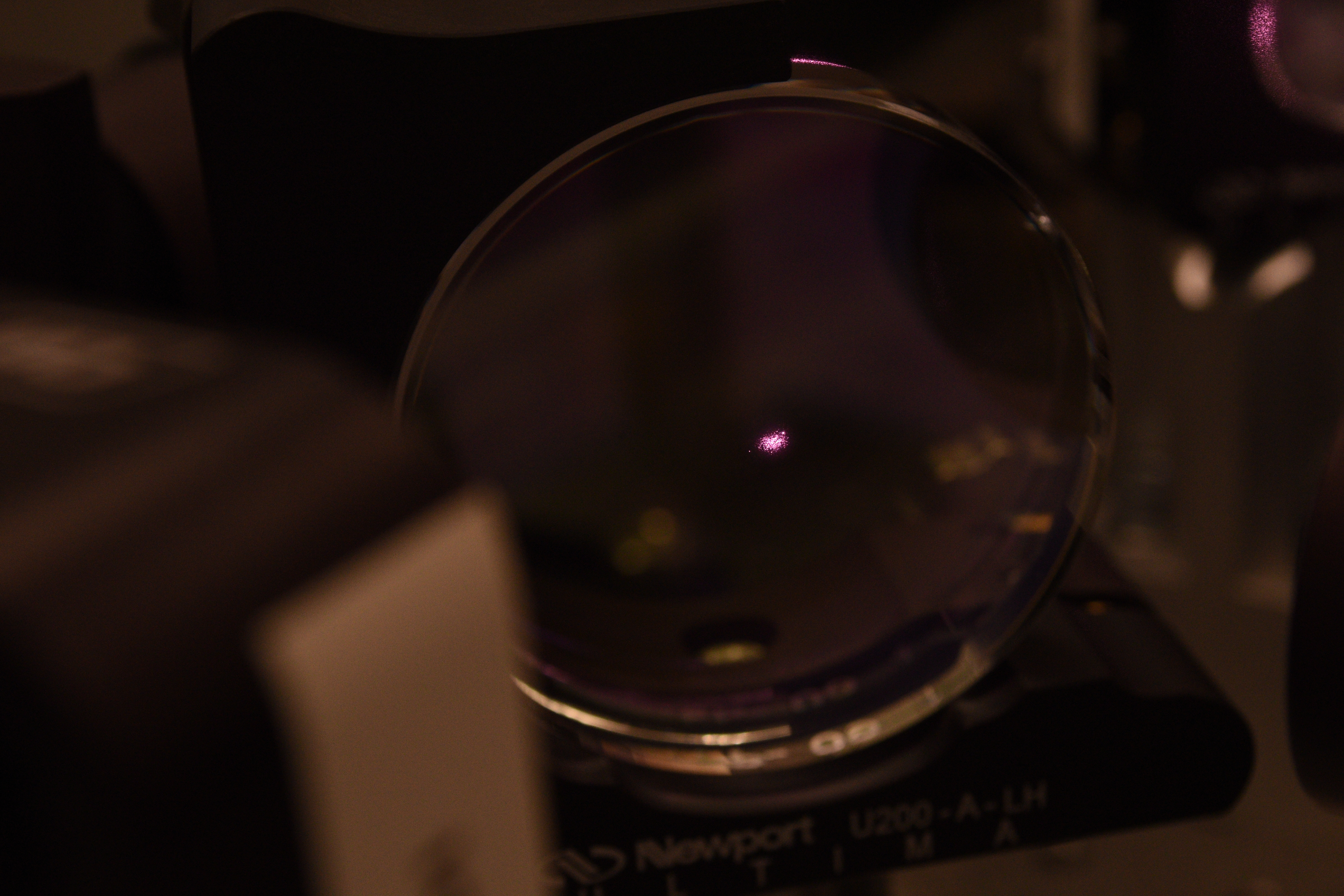
- Picture 9: Lenses look OK. Note that you see three spots in L1 but the two are actually EOM output and the ghost beam on the EOM case seen through the lens.
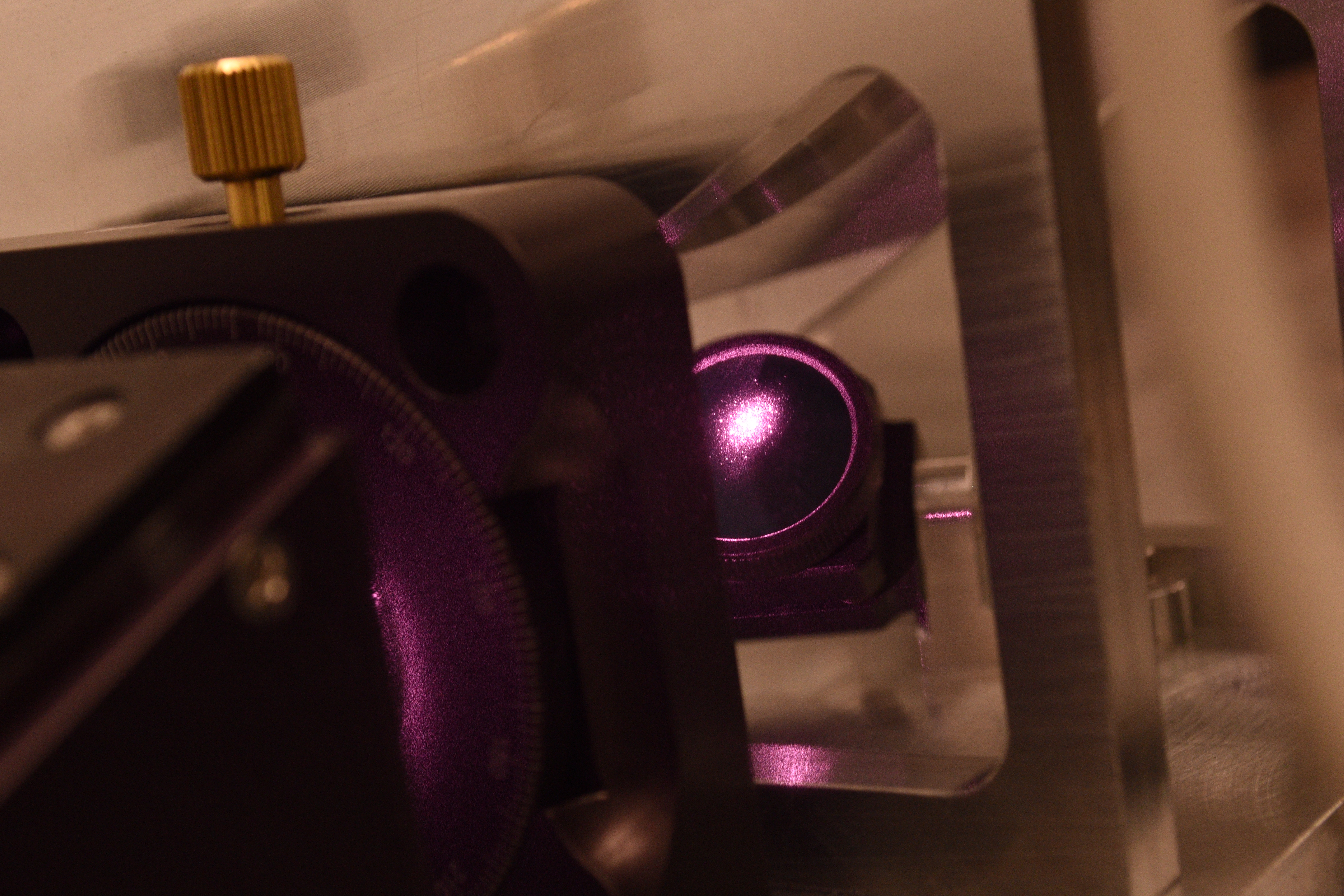
- Picture 10: Corner mirror (IO-MB_M3) in front of the motorized HWP rotator.
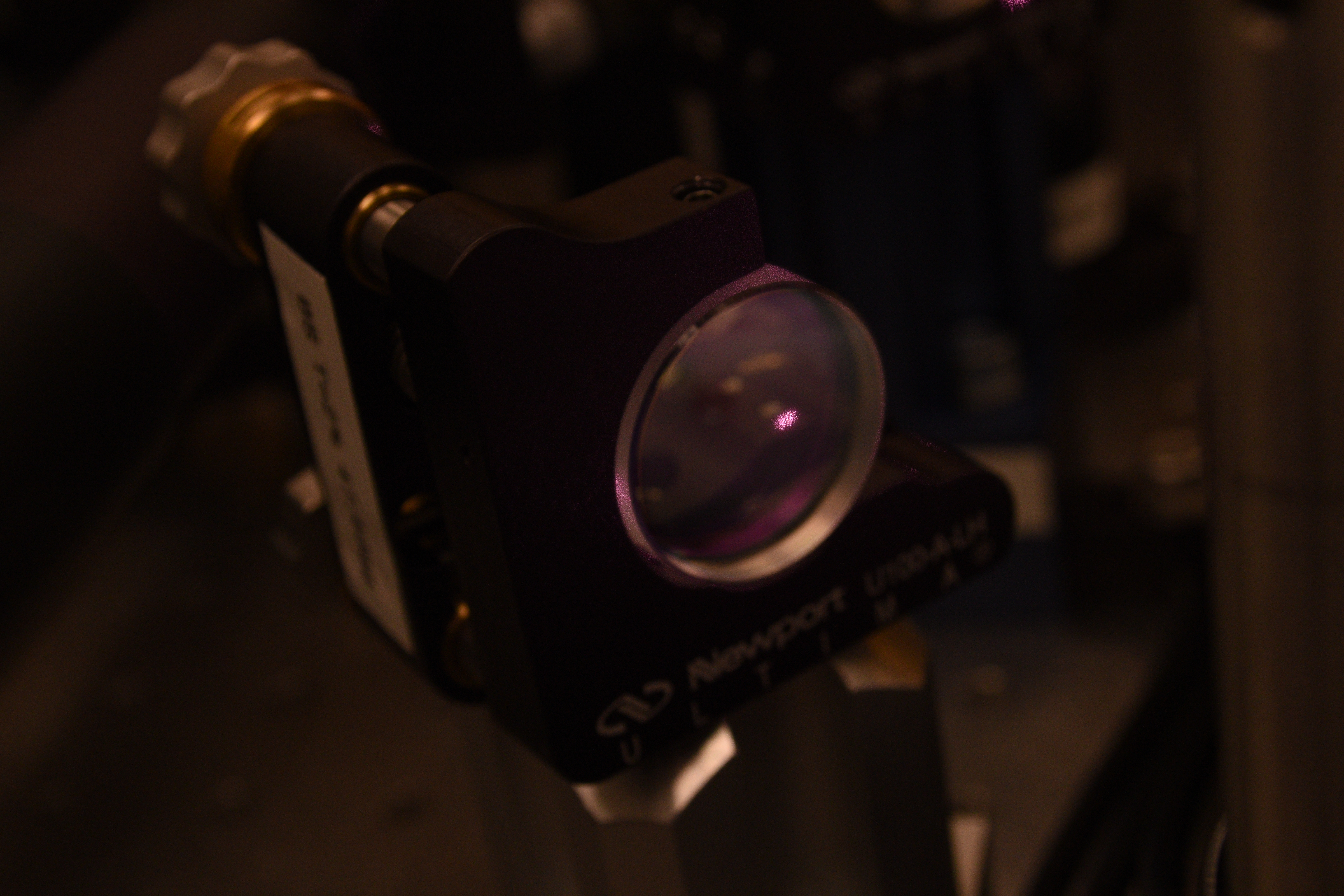
- Picture 11: Motorized HWP rotator. Some scattered light (?) is hitting the mount.
- No picture for TFPs, they were very hard to photograph, but the first TFP looked OK when viewed using the IR viewer.
- Picture 12 shows the steering mirror below the first TFP that receives the rejected light.
- Very hard to picture any scattered light from the periscope mirrors when the power was set to 2W. Which already tells us that there's no scattering/clipping at 1% or even 0.1% level (on these optics).
- Could not take a picture of the PZT mirror, very hard to have a good view of the mirror surface.
- Picture 13 and 14: These are between the L2 lens and the corner mirror, IRIS1 is close to L2 and IRIS2 is about a foot downstream. Both look pretty good, if anything the beam might be a bit high on IRIS1.
- Picture 15:
This is an iris right behind the lens for the bottom periscope mirror transmission (IO_AB_L4).(Update later. It looks like an iris between the PZT mirror and the bottom periscope mirror though that doesn't change the conclusion.) It's off-centered, but Jason thinks that this iris was set a long, long, long time ago and cannot be trusted. - Picture 16: Wincam was placed between the iris pictured above and IO_AB_BS1.
- The distance from the downstream face of the lens holder of IO_AB_L4 and the front of the the attenuator stack was measured to be 76.5mm.
- The Wincam sensor to the front of the stack is known to be 72.3mm.
- The post holder for Wincam was left on the table so people can put Wincam in the same position later if necessary.