Jennie W, Keita,
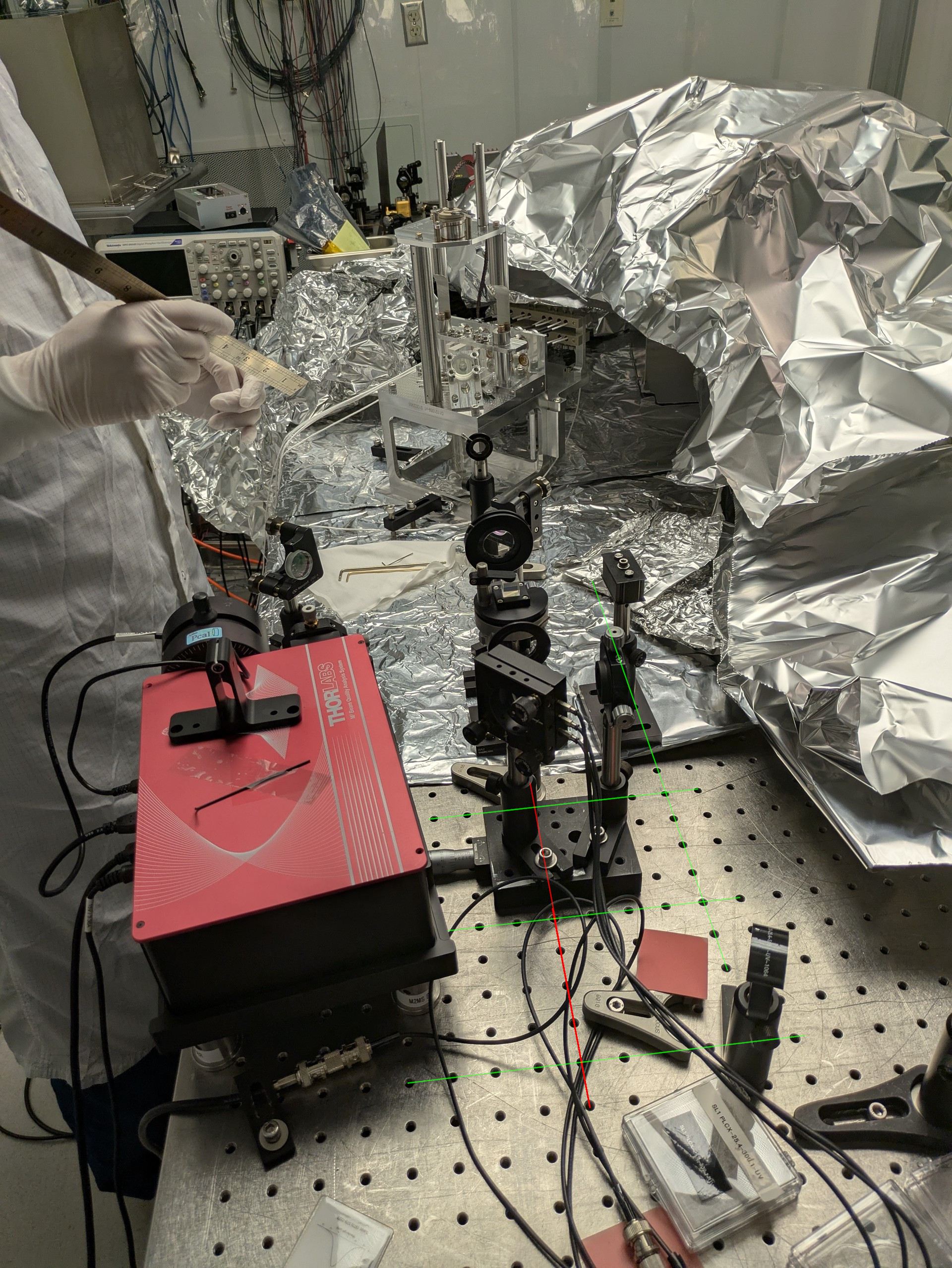
Since we don't have an easy way of scanning the input beam in the vertical direction, Keita used the pitch of the PZT steering mirror to do the scan and we read out the DC voltages for each PD.
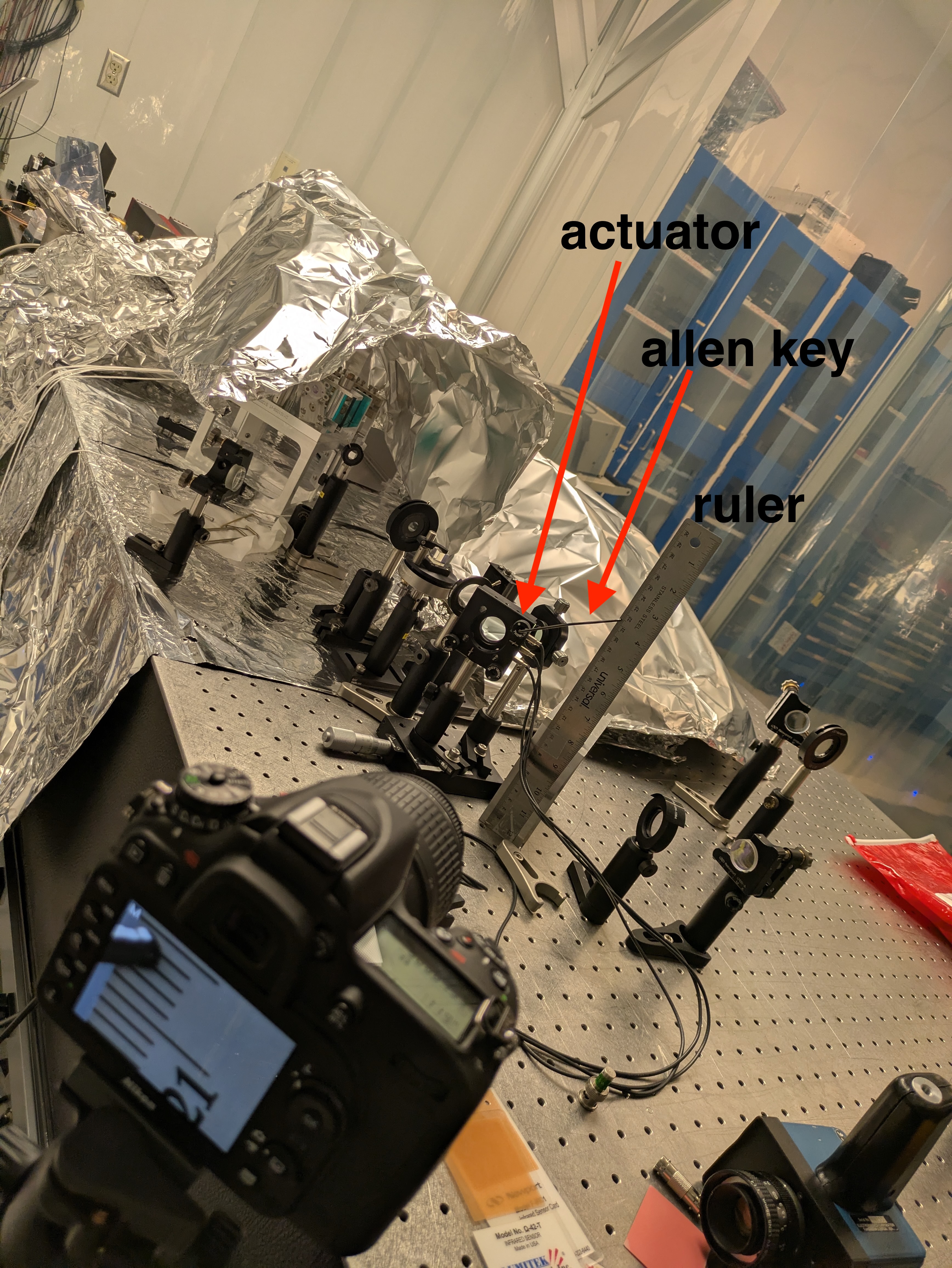
The beam position can be inferred from the pictures setup - see photo. As the pitch actuator on the steering mirror is rotated the allen key which is in the hole in the pitch actuator moves up and down relative to the ruler.
height on ruler above table = height of centre of actuator wheel above table + sqrt((allen key thickness/2)^2 + (allen key length)^2) *np.sin(ang - delta_theta)
where ang is the angle the actuator wheel is at and delta_theta is the angle from the centre line of the allen key to its corner which is used to point at the gradations on the ruler.
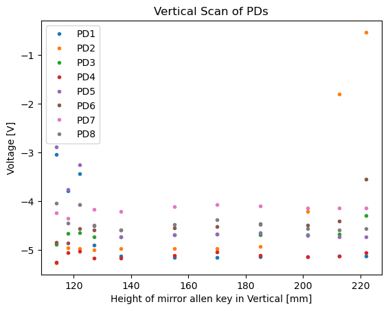
The first measurement from our alignment that Keita found yesterday that minimised the vertical dither coupling is shown. It shows voltage on each PD vs. height on the ruler.
From this and from the low DC voltages we saw on the QPD and some PDs yesterday Keita and realised we had gone too far to the edge of the QPD and some PDs.
So in the afternoon Keita realigned onto all the of PDs.
Today as we were doing measurements on it Keita realised we still had the small aperture piece in place on the array so we moved that for our second set of measurements.
The plot of voltage with ruler position and voltage with pitch wheel angle are attached.


Keita did a few more measurements in the verticall scan after I left on Friday, attached is the updated scan plot.
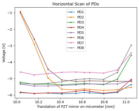
He also then set the pitch to the middle of the range (165mm on the scale in the graph) and took a horizontal scan of the PD array using the micrometer that the PZT mirror is mounted on. See second graph.
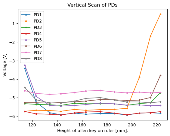
From the vertical scan of the PD array it looks like diodes 2 and 6, which are in a vertitcal line in the array, are not properly aligned. We are not sure if this is an issue with one of the beam baths through the beamsplitters/mirrors that split the light onto the four directions for each vertical pair of diodes or if these diodes are just aligned wrongly.
The above plots are not relevant any more as PD positions were adjusted since, but here are additional details for posterity.
- "height" was always measured by a ruler which had a considerable zero point offset from the table surface. That's OK because the same offset appears on both sides of the equation and cancels with each other.
- "height of centre of actuator wheel above table" =160mm.
- "allen key thickness" = 2mm.
- "allen key length" = 80.6mm.
Calculating rotation angle of the knob doesn't mean anything, that must be converted to a meaningful number like the displacement of the beam on the PD. This wasn't done for the above plots but was done to the plots with final PD positions.
- PZT mirror mount is Thorlabs KC-1-PZ series (not to be confused with KC-1-P series) and the manual actuator knob tilts the mirror by 0.4deg per revolution.
- We haven't measured the distance from the PZT mirrror to anything but took pictures that are good enough to determine the distance to the array PDs.
- Attached photos were shot during the beam profile measurement. Red and green lines are visual aid for the screw holes grid ON THE TABLE SURFACE and the yellow line is the beam path, which is pretty much directly above the red line. From the second picture, we see that the distance from the PZT mirror surface to the surface of the tenmprary mirror (SM1) is something like 9.5"+-0.5".
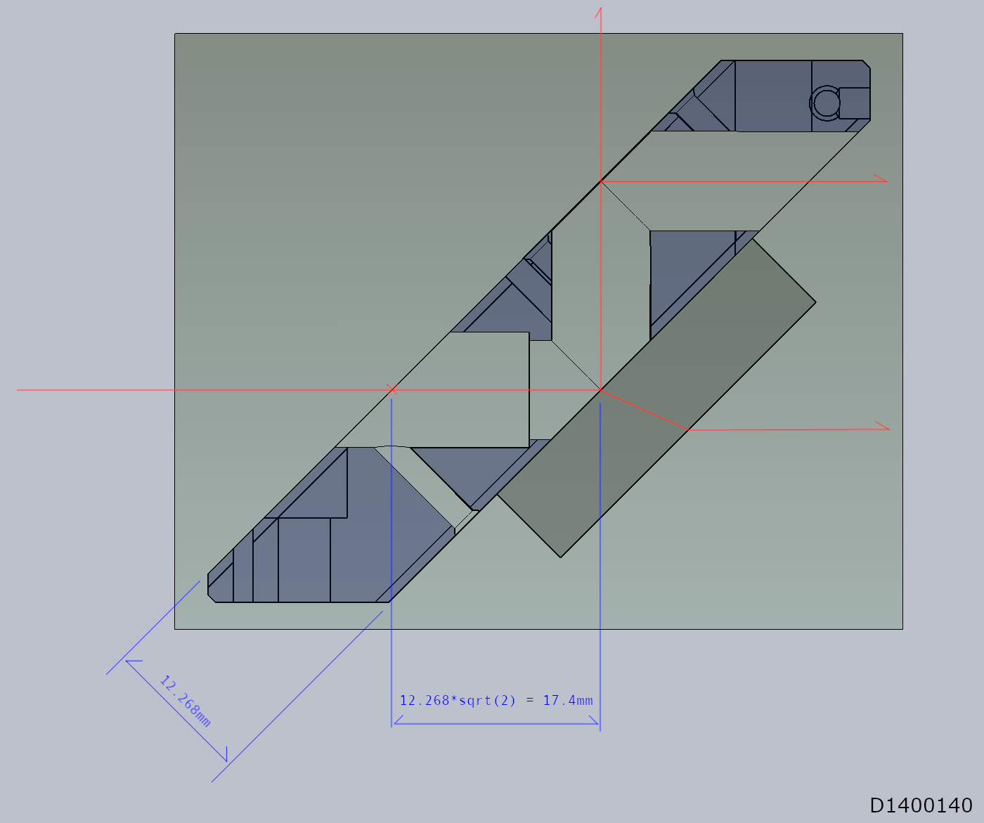
- Before removing SM1 from the table, the distance from SM1 to the ISS array input aperture location (red cross in the third attachment) was measured to be 292mm.
- The distance from the input aperture to the front surface of the periscope beam splitter on the ISS array is nominally 17.4mm (again see the third attachment).
- Finally, from the front surface of the periscope beam splitter on the ISS array to one of the PDs in the array on the first floor is 139.2mm. ("PD1" in PD Array Plate problem.docx in https://dcc.ligo.org/LIGO-E1400231. Don't trust numbers for other PDs in the document as the effect of refraction is calculated incorrectly.)
- In total, the distance from the PZT mirror to one array PD is ~690+-13mm or 690*(1+-0.02)mm. The error bar is negligible for this purpose.