Jennie W, Keita, Rahul
Monday:
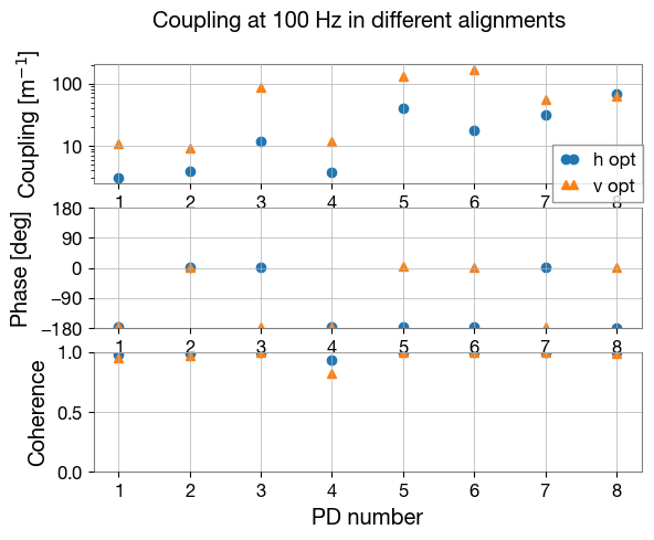
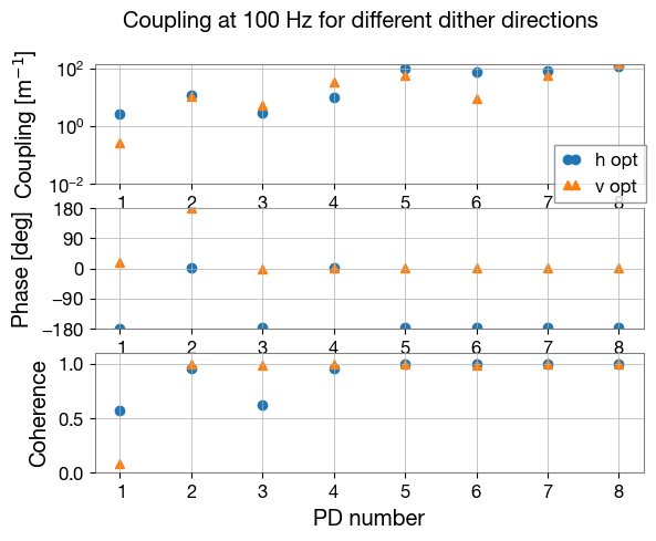
Keita and I re-optimised the array input pointing using the tilt actuator on the PZT steering mirror and the translation stage.
After taking a vertical and horizontal coupling measurement, he realised that the DC values were very low when we optimised the pointing to improve the vertical coupling. Looking at the QPD the cursor was in the bottom half and so we cannot use the QPD y-readout channel to work out the 'A' channel for either measurement (where the TF is B/A).
So for the A channel in the TF for the vertical coupling we had to use
A = QPD_X/(cos(QPD_angle*pi/180))/sqrt(2) /Calib_X where A is the times series for thr TF, 'QPD_angle' is the angle between the horizontal dither axis and the QPD x-axis, Calib_X is the calibration of motion on the QPD in the x-axis in V/mm (LHO alog #85897).
And for the A channel in the TF for the horizontal coupling we had to use
A = QPD_X/(cos(QPD_angle*pi/180))/Calib_X.
The data is plotted here.
Yesterday Keita and I double-shcked the beam size calculation I did on 26th June when we reset the alignment to the ISS array form the laser after it got bumped (we think). The beam size calculated was 0.23 mm beam radius on PD1 (the one with no transmissions through the mirrors) in x direction and 0.20 mm in y direction. The beam size calculated on the QPD was 0.20 mm in x direction and 0.19 mm in y direction. The waist should be close to this point (behind the plane of the array photodiodes) as the Rayleigh range is 9cm in x direction and 10cm in the y direction.
This check is because our beam calibration as reported in this entry, seems to be at least a factor of 2 off from Mayank and Shiva's measurements reported here (dcc LIGO-T2500077).
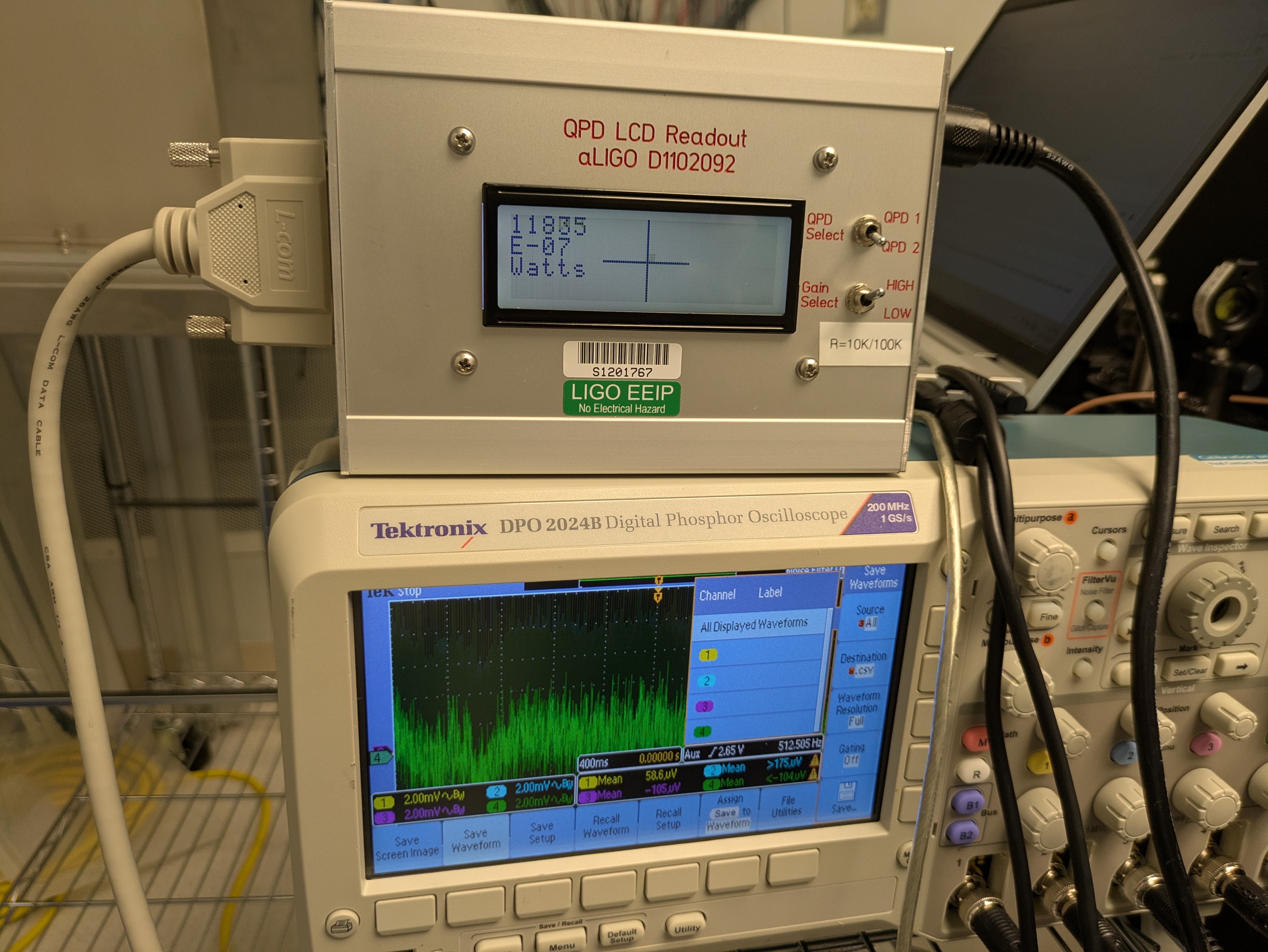
Since we already know the QPD was slightly off from our measurements on the 6th October, Keita and Rahul went in and retook the calibration measurements of volts on the QPD to mm on the QPD.
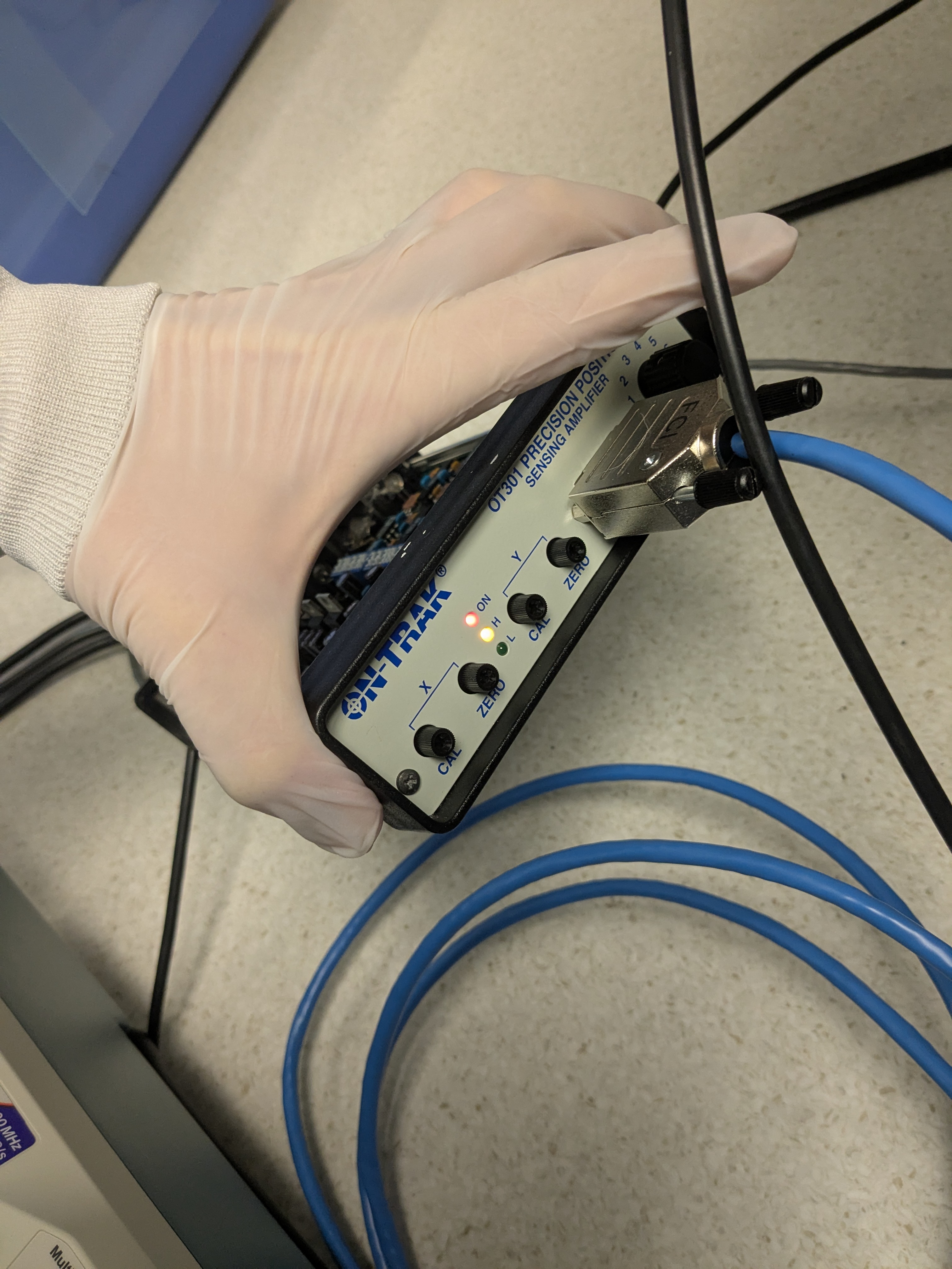
In the process Keita noticed that the ON-TRAK amplifier for the QPD had the H indicator lit and so was saturating. He turned the input pump current down from 130mA to120mA and the gain value on the amplifier from G3 (64k ohm) to G2 (16k ohm). The QPD was also recentred on the input pointing position where we had good vertical and horizontal coupling as we had left it in the position we found on Monday where it was off in yaw. We had to do several iterations of alignment switching between vertical and horizontal dither and still could only find a place where the coupling of PDs 1-4 were optimised. PDs 5-8 have bad coupling at this point. At this position we also took calibration measurments where we scanned the beam and noted down the voltage on the QPD X, Y and SUM channels.
Keita notes that for the QPD to be linear the voltages need to be below +/- 7V.
I will attach the final set of measurements in a comment below.
We left the alignment in this state with respect to the bullseye QPD readout.

The coupling measurement from the last measurements we took on Tuesday is here, and the calibration of the motion on the QPD is here.
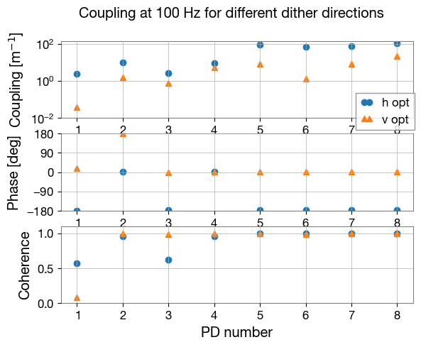

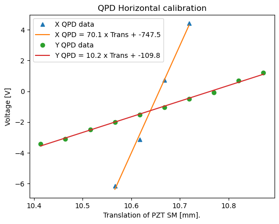
I was calibrating the above data using the Calib_X and Calib_Y values instead of by sqrt(Calib_X^2 + Calib_Y^2).
Fixed this in the attached graph.
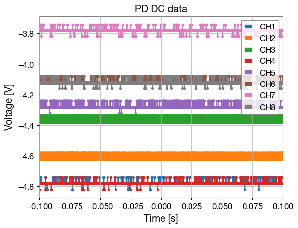
Also 3 of the PDs are starting to near the edge of their aligned range which can be seen looking at the spread of DC values on the array PDs in this graph.

