Summary:
We aligned everything such that none of 8 PDs was excellent but all were OK (we were also able to set up such that 4 pds were excellent but a few were terrible but decided not to take that), we were preparing for putting the array in storage until the installation, only to find that something is wrong with the design of the asymmetric QPD clamp D1300963-V2. It's unusable as is.
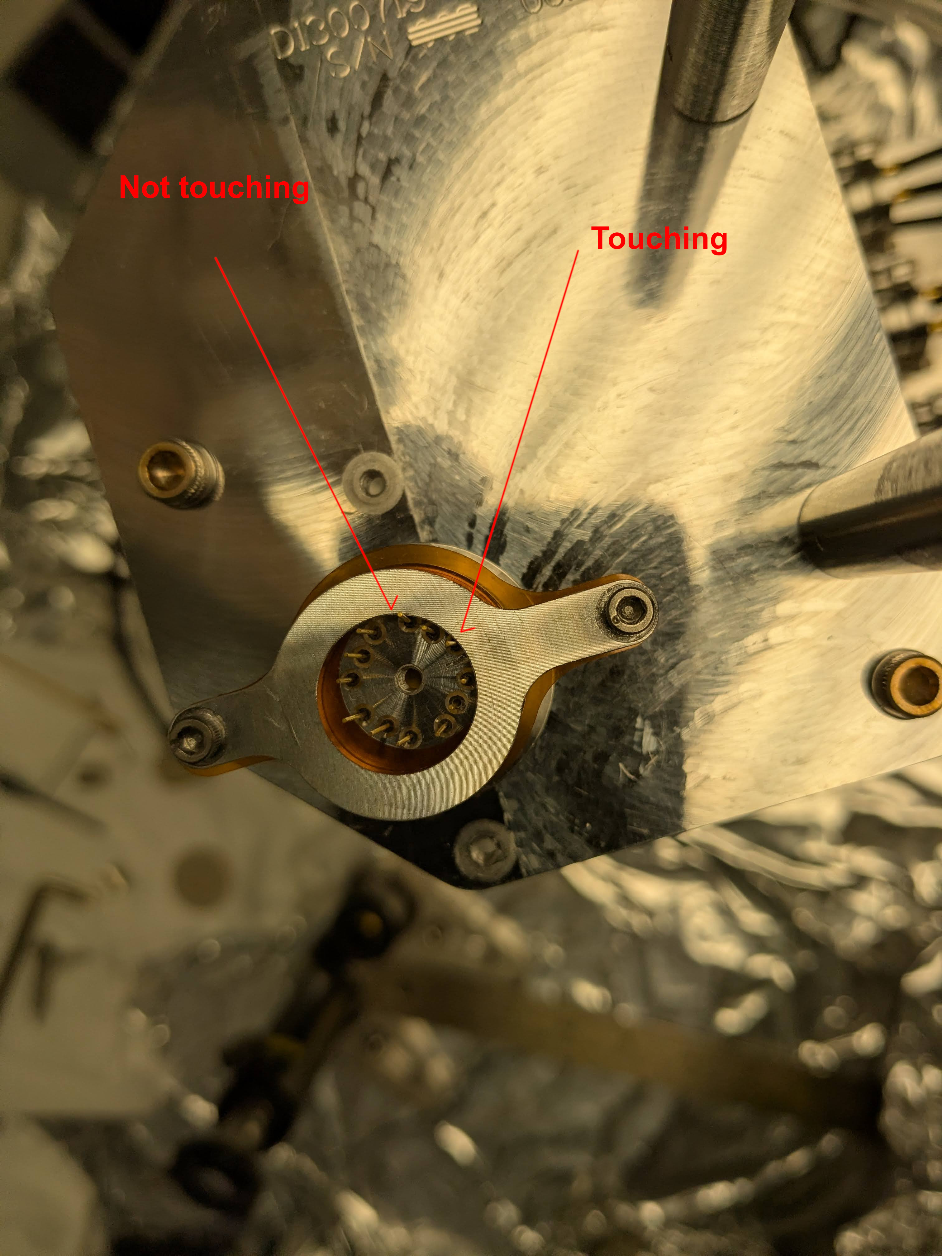
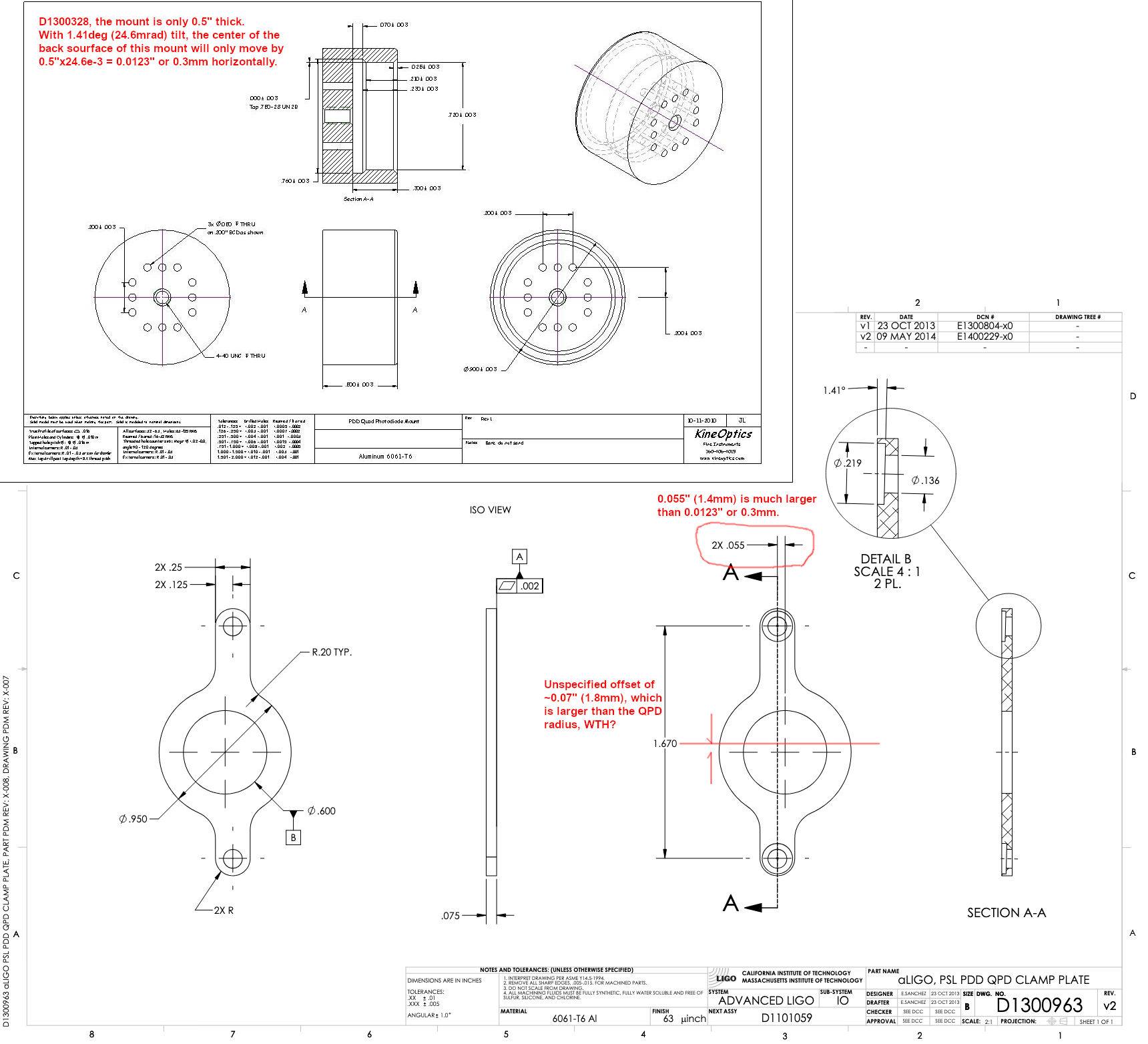
QPD clamp doesn't constrain the position of the QPD laterally, and there's a gross mismatch between the position of properly aligned QPD and that of the center hole of the QPD clamp. Because of that, when QPD is properly positioned, one of the QPD pins will touch the QPD clamp and be grounded unless the QPD connector is fixed such a way to pull the QPD pins sideways. Fortunately but sadly, the old non-tilt QPD clamp D1300963-V1 works better, so we'll use that.
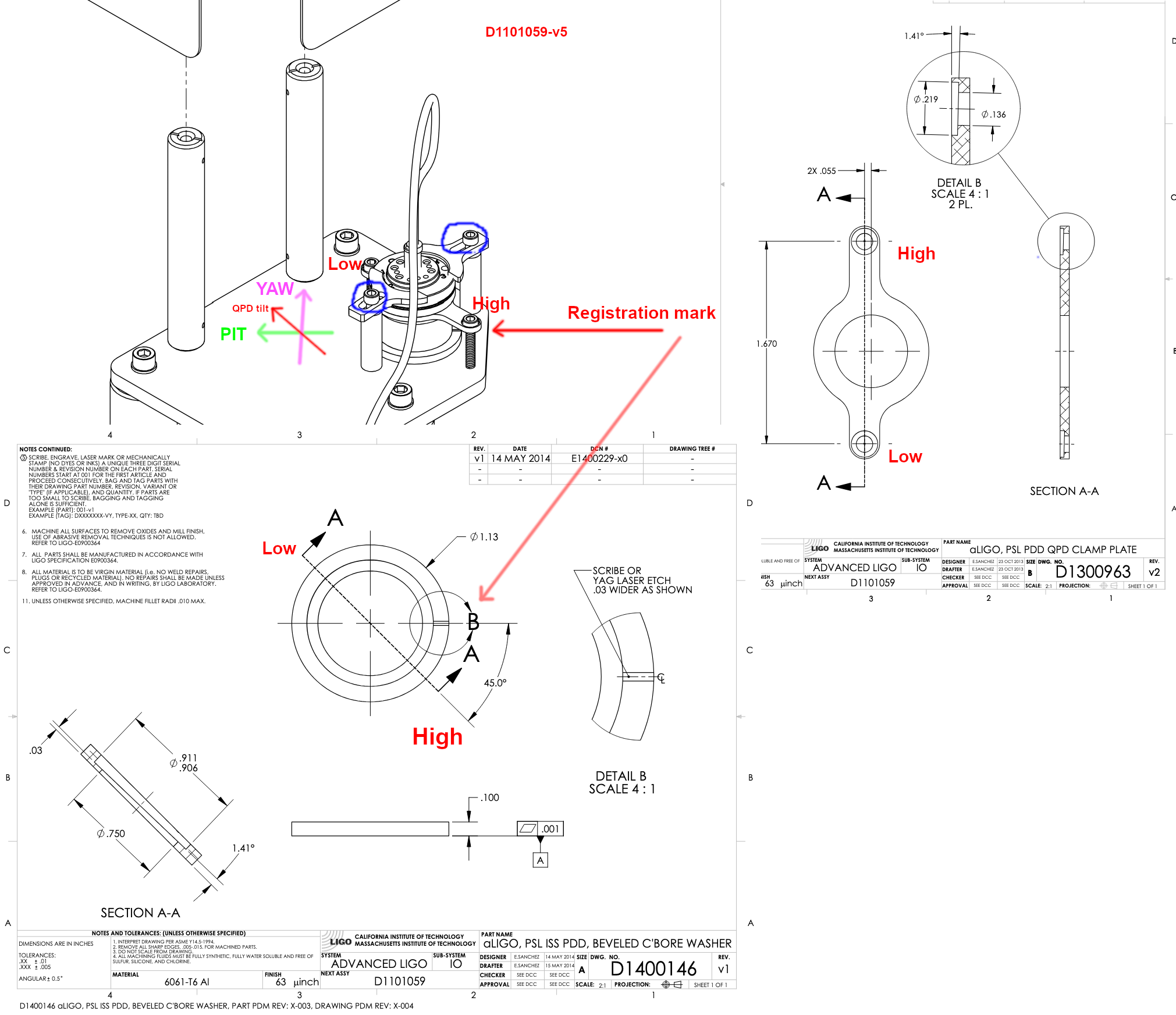
Another minor issue, is that there seems to be a confusion as to the direction of the QPD tilt in terms of the word "pitch" and "yaw". The way the QPD is tilted in D1101059-v5 (this is how things are set up in the lab as of now) doesn't seem to follow the design intent of ECR E1400231 though it follows the word of it. After confirming that this is the case with systems, we'll change the QPD tilt direction (or not). This means that we're not ready to put everything in storage quite yet.
None of these affect the PD array alignment we've done, this is just a problem of the QPD.
Pin grounding issue due to the QPD clamp design.
I loosened the screws for the QPD connector clamps (circled in blue in the first attachment) and the output of the QPD preamp got crazy with super large 60Hz noise and large DC SUM even though there was no laser light.
I disconnected the QPD connector, removed the connector clamps too, and found that one pin of the QPD was short circuited to the ground via the QPD clamp (not to be confused with the QPC connector clamps, see 2nd attachment).
Turns out, the offending pin was isolated during our adjustments all the time because the QPD connector clamps were putting enough lateral pressure as well as down such that the pins were slightly bent from the offending side. I was able to reattach the connector, push it laterally while tightening the clamp screws, and confirm that the QPD functioned fine. But this is not really where we wanted to be.
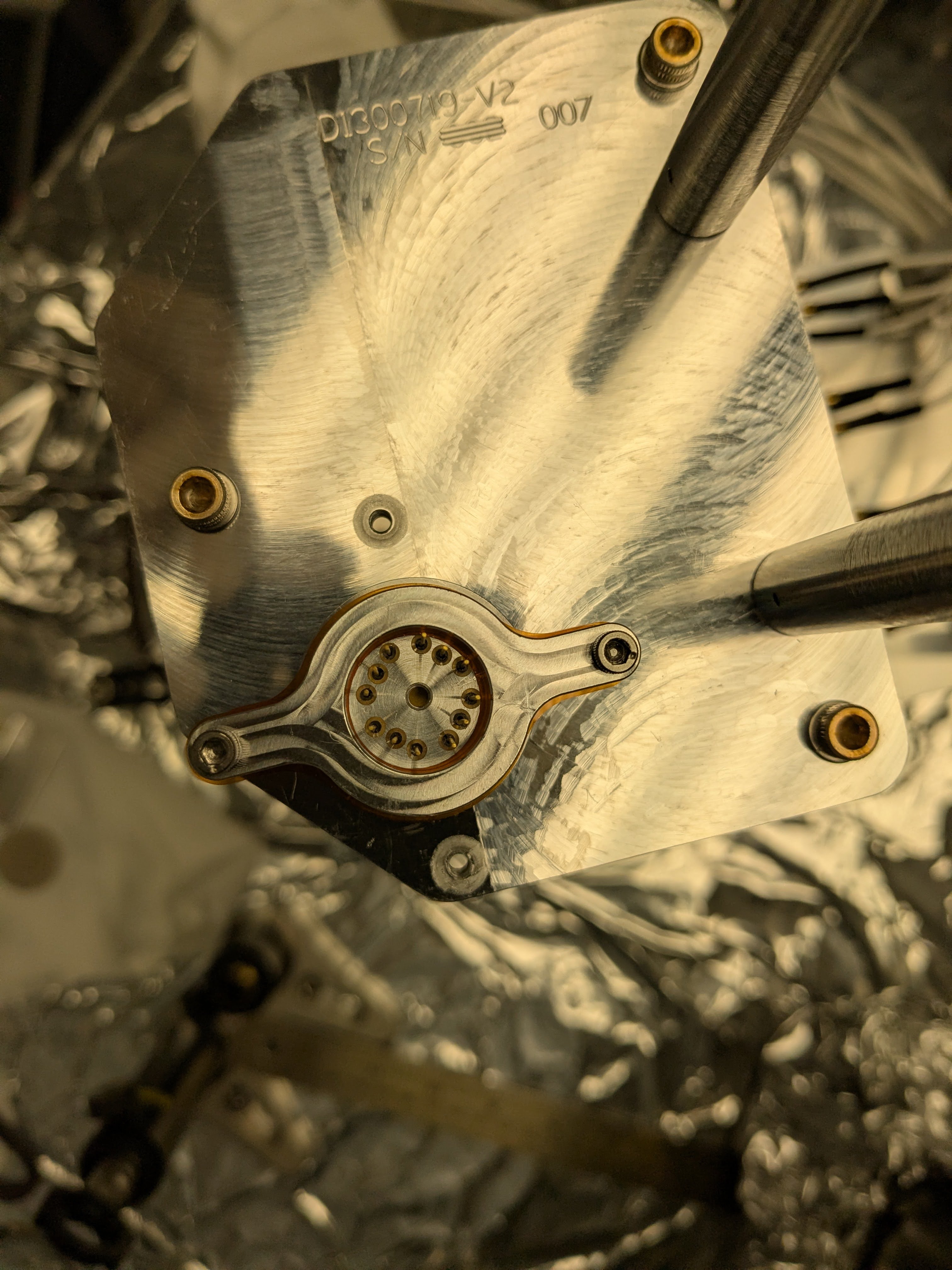
I rotated the QPD clamp 180 degrees (which turns out to make more sense judging from the drawings in the first attachment), which moved the QPD. Since the beam radius is about 0.2mm, if the QPD moves by 0.2mm it's not useful as a reference of the in-lab beam position. I turned the laser on, repositioned the QPD back to where it should be, but the pin on the opposite side started touching. (Sorry no picture.)
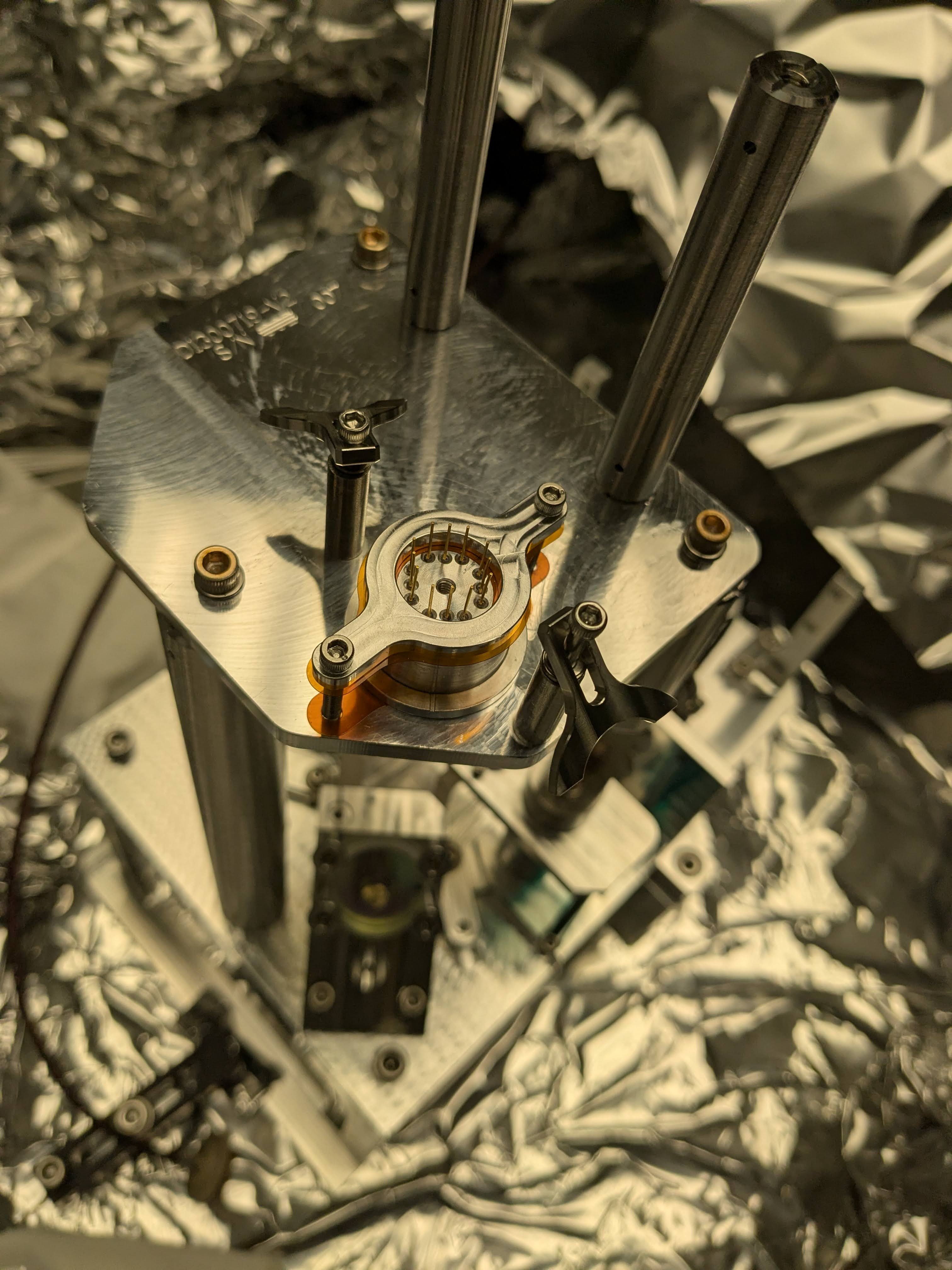
I put the old non-tilt version clamp and it was much, much better (attachment 3). It's annoying because the screw holes don't have an angled recess. The screw head is tilted relative to the mating surface on the clamp, contacting at a single point, and tightening/loosening the screw tend to move the QPD. But it's possible to carefully tighten one screw a bit, then the other one a bit, repeat that dozen times or so until nothing moves even when pushed firmly by finger. After that, you can still move the QPD by tiny amounts by tapping the QPD assy by bigger Allen key. Then tighten again.
What's going on here?
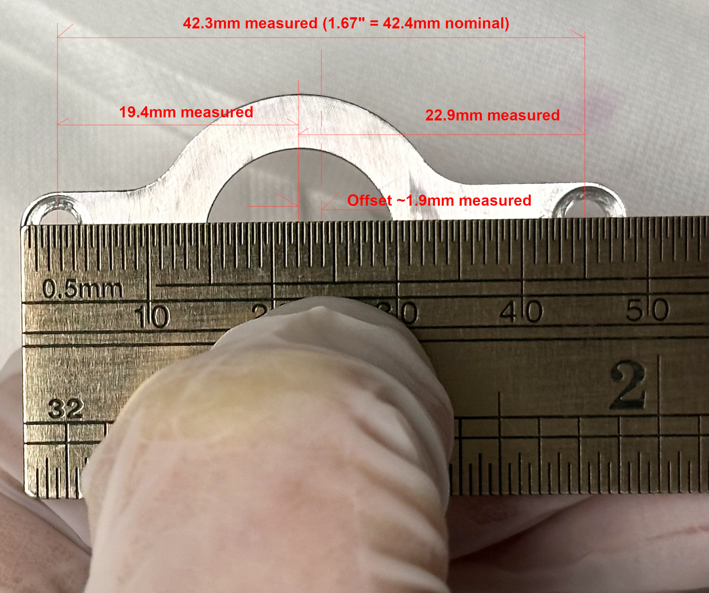
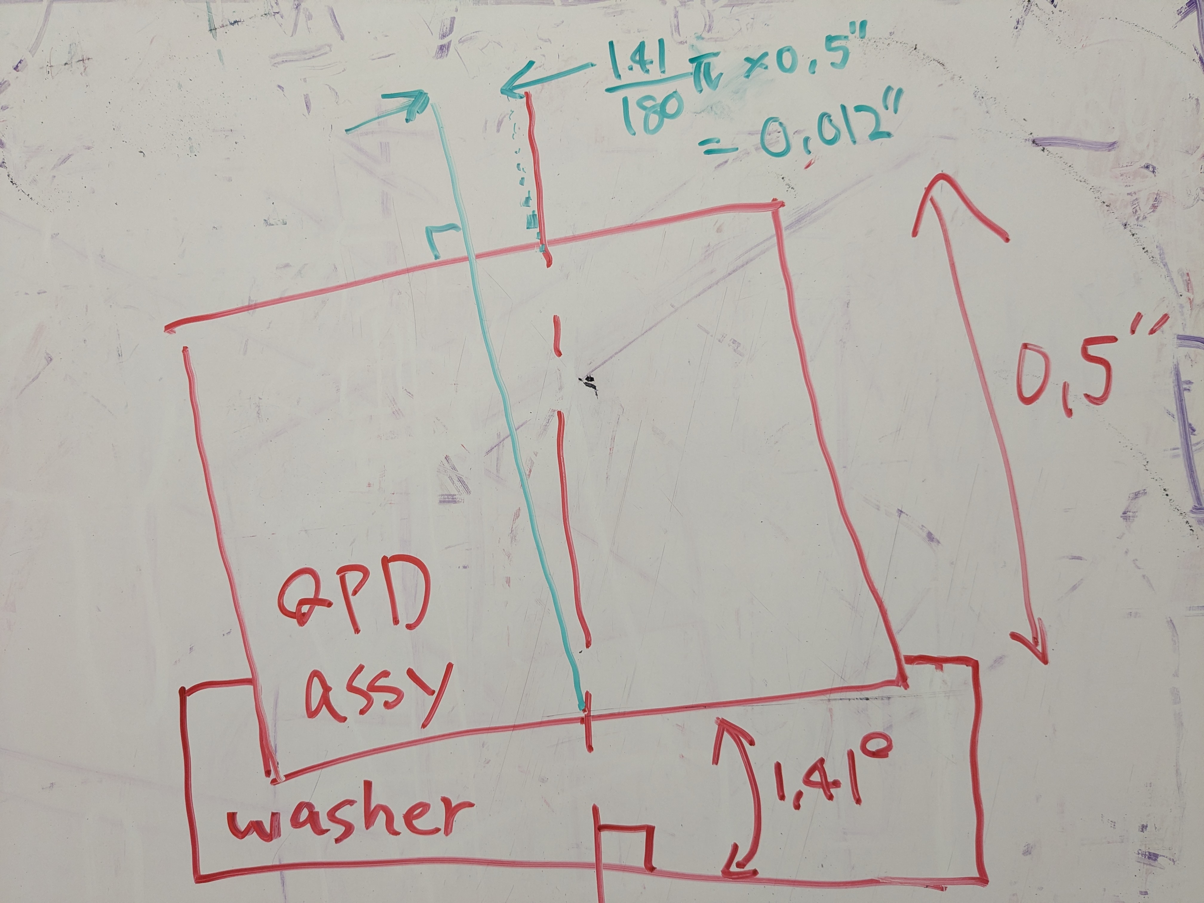
In the 4th attachment, you can see that the "center" hole of the QPD clamp is offset by 0.55" (1.4mm) in the direction orthogonal to A-A, and about 0.07" (even though this number is not specified anywhere in the drawing) or 1.8mm in A-A direction. So the total lateral offset is sqrt(1.4^2+1.8^2)~2.3mm. OTOH, the QPD assy is only 0.5" thick, so the lateral shift arising from the 1.41deg tilt at the back of the QPD assy is just 1.41/180*pi*0.5=0.0123" or 0.3mm.
Given that the beam position relative to the array structure is determined by the array itself and not by how the QPD is mounted, 2.3mm lateral shift is impossibly large, something must be wrong in the design. The 5th attachment is a visual aid for you.
Anyway, we'll use the old clamp, it's not worth designing and manufacturing new ones at this point.
QPD tilt direction.
If you go back to the first attachment, the QPD is tilted in a direction indicated by a red "tilt" arrow in the lab as we just followed the drawing.
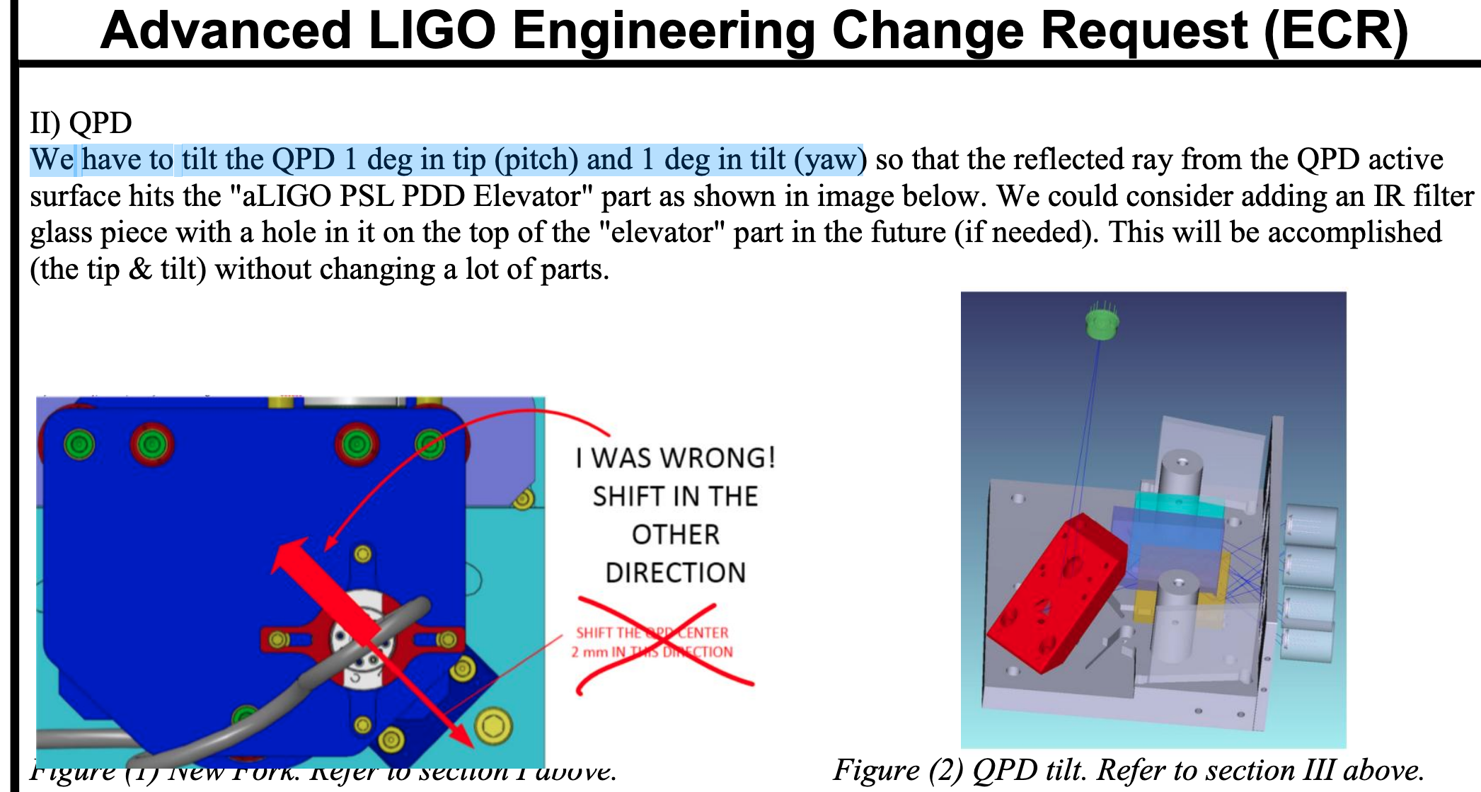
The ECR E1400231 says "We have to tilt the QPD 1 deg in tip (pitch) and 1 deg in tilt (yaw)" and it sounds as if it colloborates with the drawing.
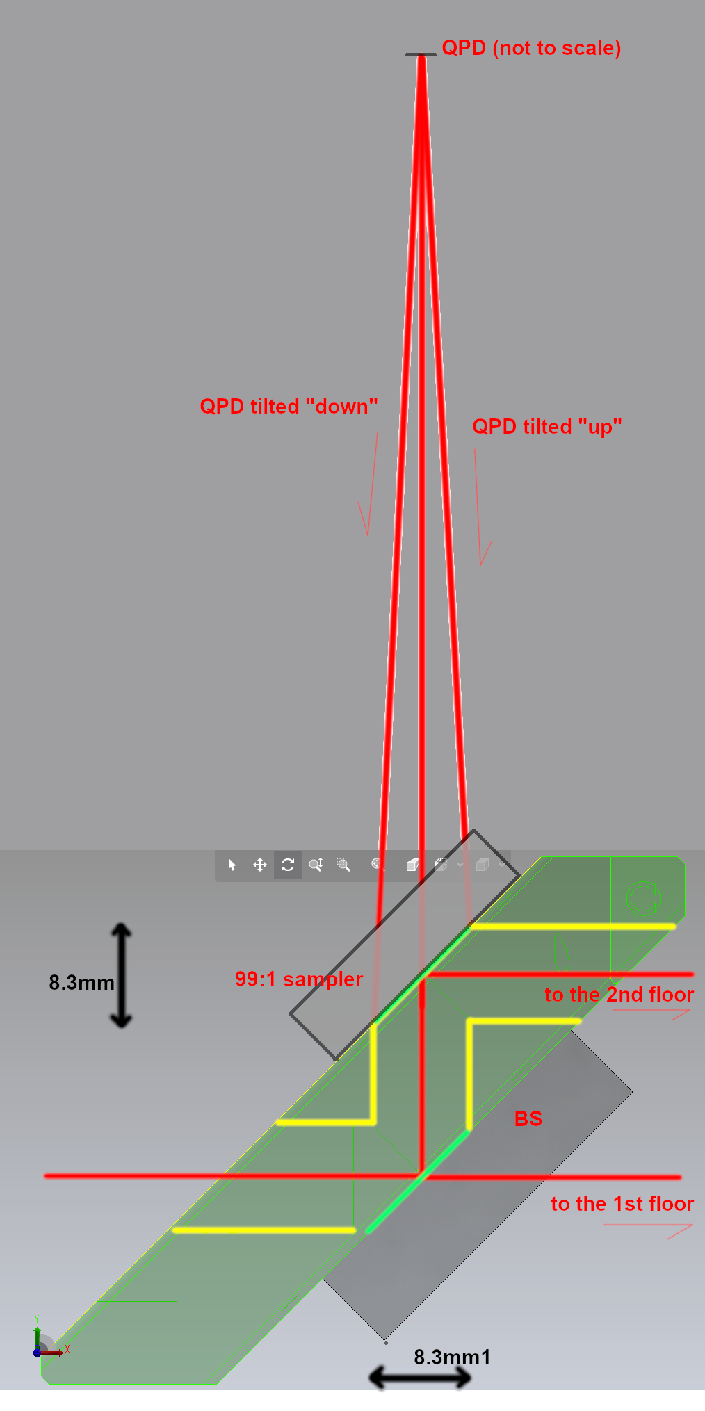
However, I suspect that "pitch" and "yaw" in the above sentence might have been misused. In the right figure of the 6th attachment (screeshot of ECR unedited), it seems that the QPD reflection hits the elevator (the red 45 degree thing in the figure) at around 6 O'clock position around the eliptic exit hole, which means that the QPD is tilted in its optical PIT. If it's really tilted 1 degree in optical PIT and 1 degree in optical YAW, the reflection will hit something like 7:30 position instead of 6:00.
That makes sense as the design intent of the ECR is to make sure that the QPD reflection will not go back into the exit hole. The 7th attachment is a side view I made, red lines represent the IR beams, yellow lines the internal hole(s) in the elevator, and green lines the aperture of the two eliptical exit holes. Nothing is to scale, but hopefully you agree that, in order to steer the QPD reflection outside of the exit hole aperture, PIT UP requires the largest tilt and PIT DOWN requires the least tilt. We have a fixed tilt of QPD, so it's best to PIT DOWN, that's what I read from the ECR. If you don't know which angle is bigger or smaller, see attachment 8.
Anyway, I'll ask Callum if my interpretation is correct, and will act accordingly.
A followup summary:
Callum and Betsy say that I'm in the best position to judge, so I decided to tilt the QPD in its optical PIT.
Turns out that the QPD was already tilted in QPD's optical PIT so everything is fine(-ish). We'll put the unit in storage tomorrow.
Seems like we were tricked by the part drawing of the tilt washer D1400146, not the assembly drawing D1101059.
Details:
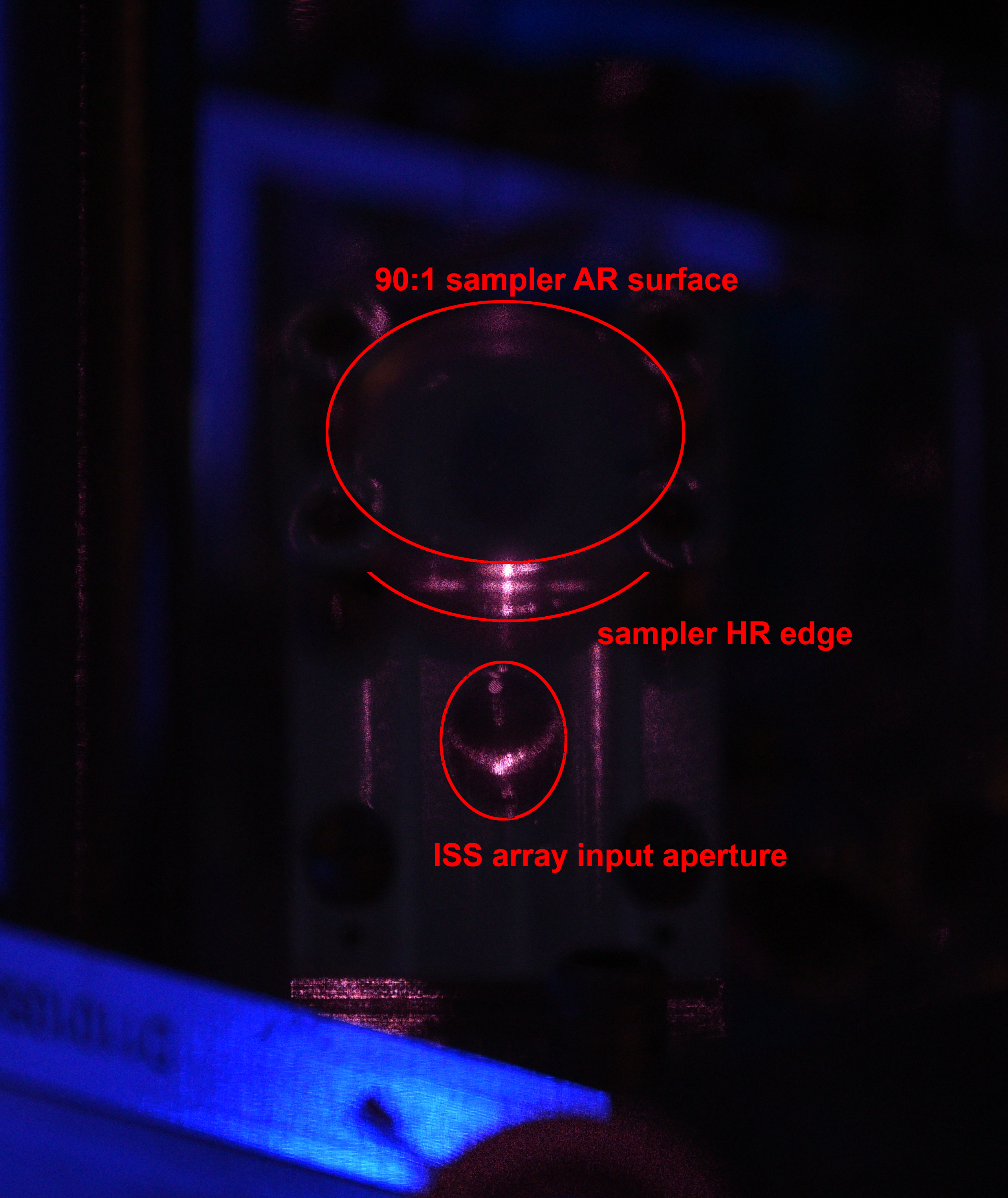
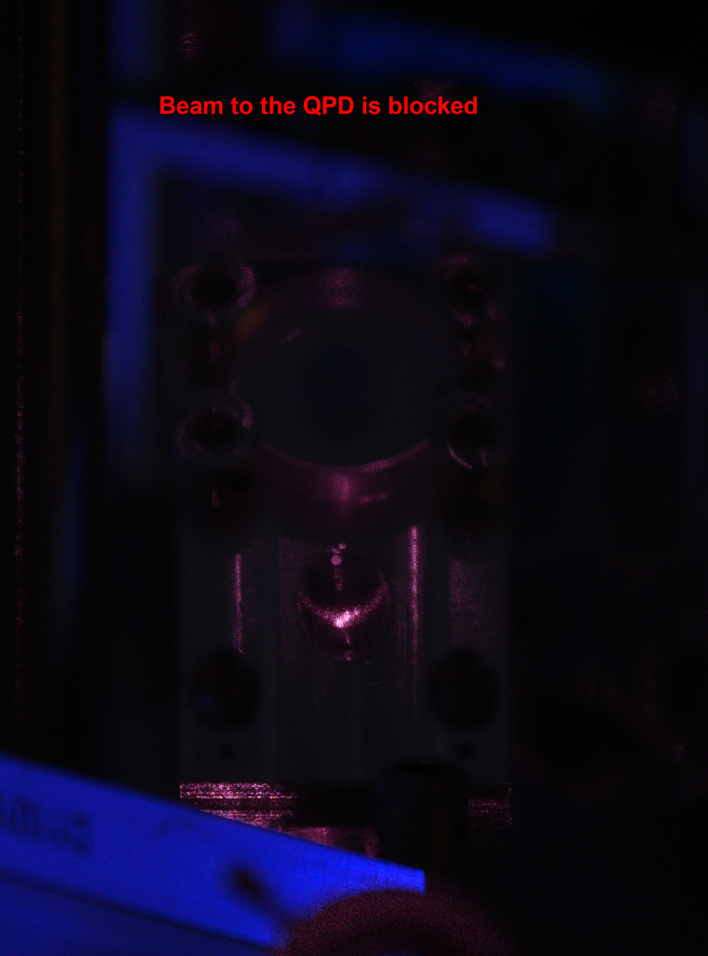
Before rotating anything, I wanted to see if the reflection from QPD could be seen on the aluminum part using the IR viewer, and indeed we could see something. The first attachment shows that some kind of diffraction pattern is hitting the barrel of the 1" 99:1 sampler in PIT. The second attachment shows that the bright spots are gone when Rahul blocked the beam going to QPD, so it's clearly due to the reflection of the QPD. The pattern might come from the gaps at the QPD center. It wasn't clear if the reflection was directly hitting the barrel through AR, or if it hits 99% coating and reflected towards the barrel.
(There was also some IR visible in the input aperture but the beam is much smaller than this aperture, I believe we're seeing the scattered light coming back to this aperture from inside the array structure.)
We pulled the spare tilt washer D1400146-V1 (drawing with my red lines in the 3rd attachment) and measured the depth of the recess at 12 O'clock position (red E in the drawing), 3:00 (B), 6:00 (C) and 9:00 (D) using a caliper. It's a rough measurement, but anyway we repeated the measurement twice and got the following:
| A | B (registration mark) | C | D | |
| Meas 1 | 1.45 mm | 1.21 | 1.45 | 1.70 |
| Meas 2 | 1.41 | 1.21 | 1.49 | 1.71 |
| Average | 1.43 | 1.21 | 1.47 | 1.705 |
Clearly B at the registration mark is the shallowest position and the opposite position D is the deepest. The recess diameter was measured to be 23.0mm (specified as between .906 and .911" or 23.01 to 23.14mm), so the tilt of the recess as measured is (1.705-1.21)/23 ~ 21.5mrad or 1.2 deg, which reasonably agrees with 1.41deg specification and, more importantly, these measurements cannot be explained if the part was manufactured as specified in the drawing.
It seems that the drawing of the tilt washer D1400146 is incorrect or at least doesn't agree with reality, and the assembly drawing D1101059 was correct in that following that will give us the QPD tilt along optical PIT.
Seeing how the QPD reflection hits the barrel of the 99:1 sampler, the ghost beam dumping doesn't look well thought out but that's what it is.
4th picture shows the registration mark of the tilt ring as was set in the lab for future reference.
We've done the last QPD scan (turns out that I happened to set the PIT-YAW angle really well). Data will be posted later. Now we're ready to pack things up.

We "measured" the dimension of the new (non-functional) QPD clamp D1300963-V2 by taking a picture with a ruler.
The offset of the center bore along the line connecting the two screw holes was measured to be about 1.9mm, which agrees pretty well with the above alog where I wrote "(even though this number is not specified anywhere in the drawing) or 1.8mm".