J. Freed,
I took Phase noise measurements of the 2 channel Keysight 33600A waveform generator for its use in building SPI Pathfinder in the optics lab before install. Going only off of the phase noise graphs, it is sufficient as it shows comparable results to the SRS which had a phase noise considered to be good enough for SPI pathfinder.
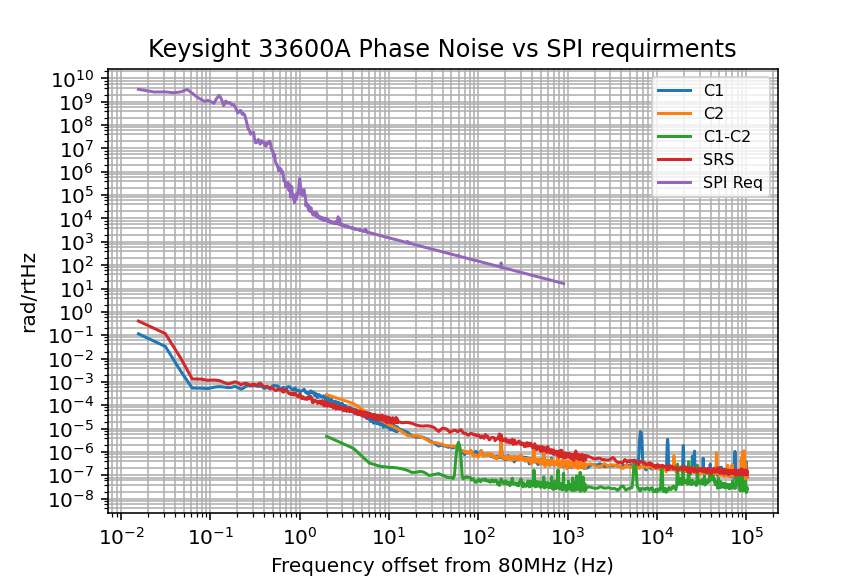
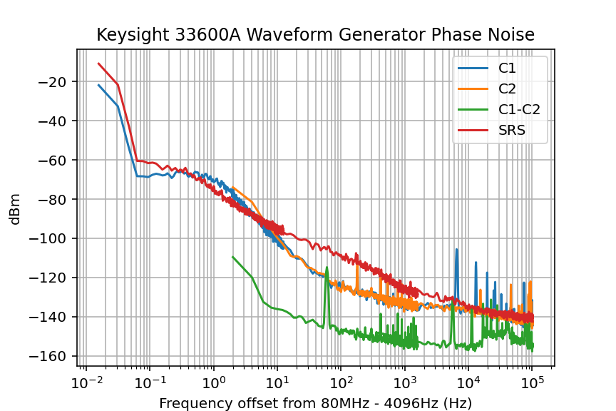
Key.png Shows the phase noise results. C1, C2 are the phase noise results for Channel 1 and Channel 2 on the Keysight, respectively. (Set up shown below). Shown for comparison the SRS SG392, which was suggested as a possible frequency source for SPI. The last measurement shown is the direct measurement of phase noise between the 2 channels of the Keysight. This measurement reflects the intended use case of the Keysight for SPI. As we need 2 frequencies at slightly different frequencies locked to each other and SPI will be measuring the output phase difference. Note the 60Hz peak; most likely caused by unclean AC power. This is why we are not using an AC powered device in the final installation.
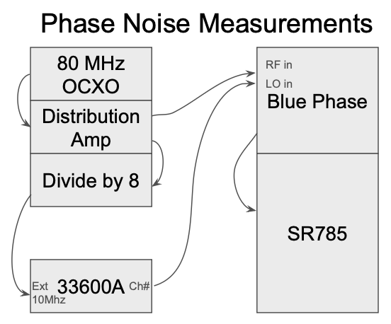
Screenshot2025-12-01at50150 PM.png Shows the setup for C1, and C2. measurements. The SRS value was found with the same set up, just replacing the Keysight 33600A with a SRS. The C1-C2 is a direct measurement by plugging both channels into the BluePhase 1000. There is no 10MHz Ext back attachment in this measurment in order to best represent Keysight's theoretical performance in the optics lab.
Edit to the other comment and the main post
After a discussion with Jeff, we figured the best course of action would be to have all the generators referenced to the same generator. In order to better compare all the results. As well as, redo the plot in the previous comment to better reflect SPIs requirements as the base standard rather than the other way around.
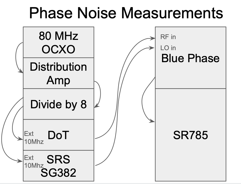
PhaseNoiseSetUp.png Is a picture of the set up, it is similar to the previous tests except everything is referenced to the SRS. One thing I failed to mention in the previous tests and is not listed in the diagram is that the divide-by-eight goes into another Distribution Amp. before heading into the Ext. 10MHz of the function generators. Also note that the Double Mixer (DM) does not have an Ext 10MHz port. Instead it takes the 80MHz signal from the first differential amp; and a sin and cos 4096Hz signal from a CDS DAC through an AI chassis. (see 81593). Also note that the OCXO measurement took a pickoff from the first Distribution Amp instead of some sort of extra DoT.
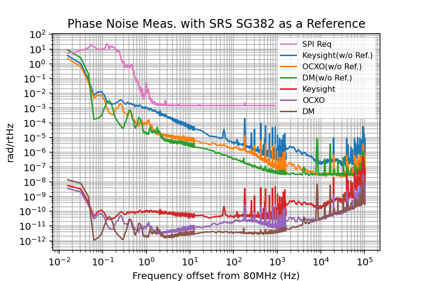
Keyrad2.png Is the graph of phase noise measurements of the Double Mixer (DM) D2400315, a LIGO 80 MHz OCXO D080702 (Which both DM and OCXO are used in the final SPI design), and a Keysight 33600A dual source waveform generator which will be used during the SPI build. The phase noise measurements were all referenced with a SRS SG382. Note that the BluePhase 1000 set up calculates values in dBc/Hz, to convert to a more directly useful value for SPI, rad/rtHz, I used the conversion:
[rad/rtHz] = sqrt(2) * 10^([dBc/Hz]/20)
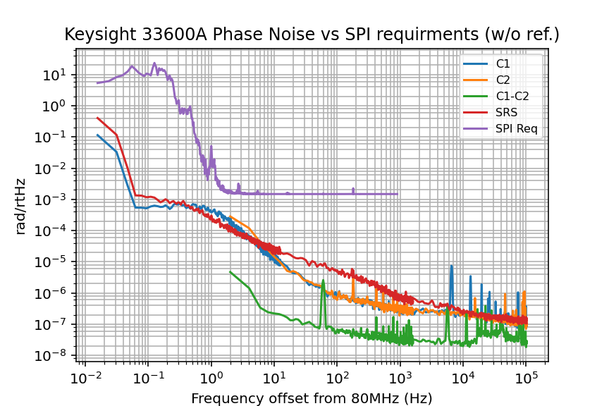
The w/o. Ref. label is a separate reference from the SRS. In SPI, there is a reference interferometer that removes noise gained along each of the arms of the main SPI Mach-Zehnder. Mathematically speaking, this subtraction has an attinuation effect on our phase noise of:
Phase Noise = D/c * f * Phase noise(w/o. Ref.)
Where D is the length mismatch in the main arm between the reference and the main interferometers (or ~30m), c is the speed of light, and f is the frequency of the phase noise. Or put another way, the plots that have the label (w/o Ref.) are the direct measurements of the phase noise while plots without that label are the theoretical effect of the noise in our system. We will experimentally test this later once SPI is installed using injections; by altering the 4096Hz CDS filter bank for the DM.
P.S. I have no idea why the OCXO noise is worse than the DM. We expected it to be better. A possibility is that since the DM measurements were taken more than a half a year ago, one of the devices was "just having a bad day" today. Investigating this, while interesting, is a lower priority than other tasks as the main goal of investigating the Keysight noise performance was achieved.
Edits to previous post. Graph: X axis label should be 'Frequency offset from 80MHz (Hz)' and y-axis label should be 'dbc'
Keyradwref.png and Keyradworef.png are the requirements for the phase noise of our oscilator with SPI having and not having a reference interferometer respectivly. In the final SPI pathfinder install, we will have a reference interferometer giving us much less stringent requirements on our oscialtors phase noise. But during the build, it may be nessisary to run tests without a reference interferometer, I plotted the without reference interferometer if that situation ever does come up.