Jennie W, Daniel S, Jeff K,
Human Readable Summary:
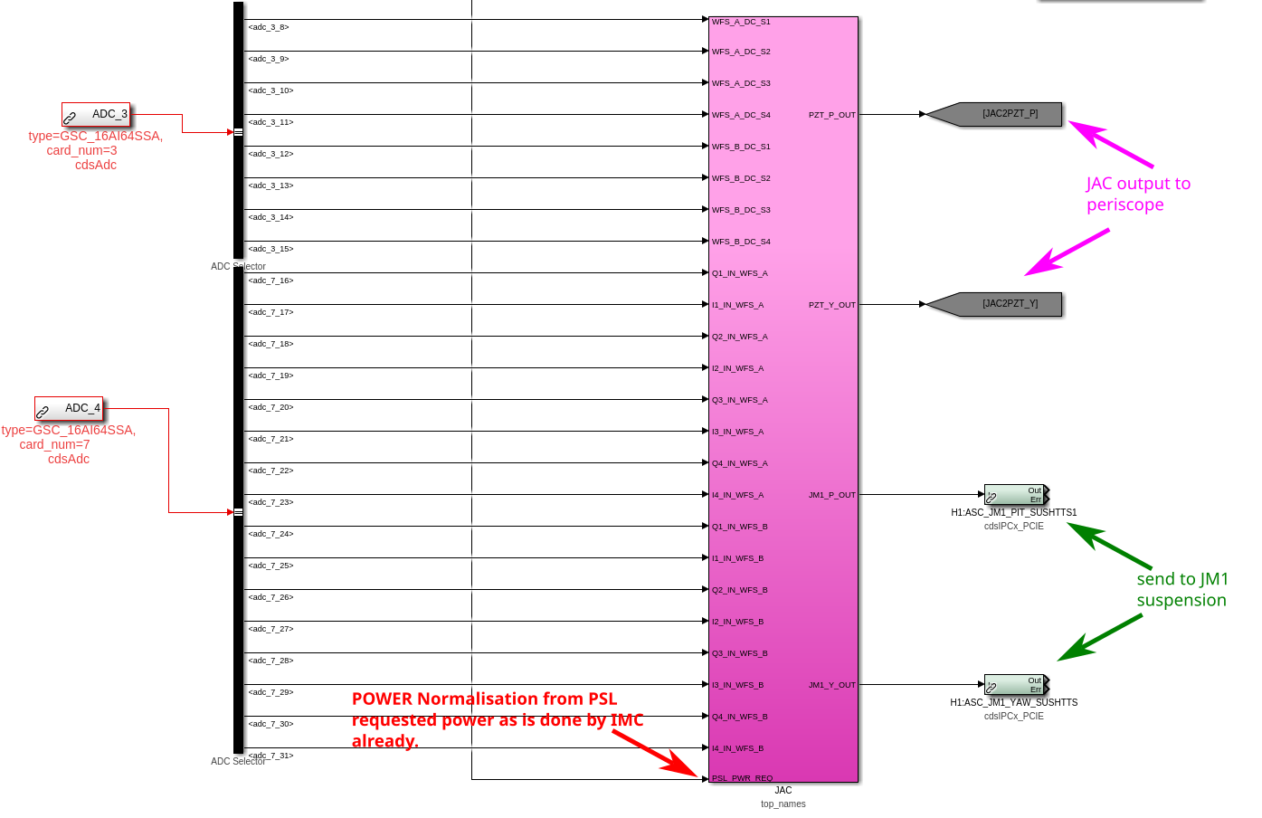
Today I finished doing the last round of changes to ascimc.mdl which adds a path to do ASC for the new jitter attenuation cavity, JAC. As part of this, the IMC will no longer be using the PSL periscope PZT as a feedback path to control input alignment and instead this path will be used to align to the JAC. We have implemented logic in the IMC ASC model to use the IMC as normal just now. We have also put in the infrastructure in this model for the JAC ASC in a JAC top_names block. The JAC has 2 WFS, 1 RF PD as input and feeds back to the PSL periscope and JM1 tip-tilt suspension for alignment. These changes were built and added to the re-locked revision in the svn.
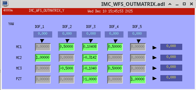
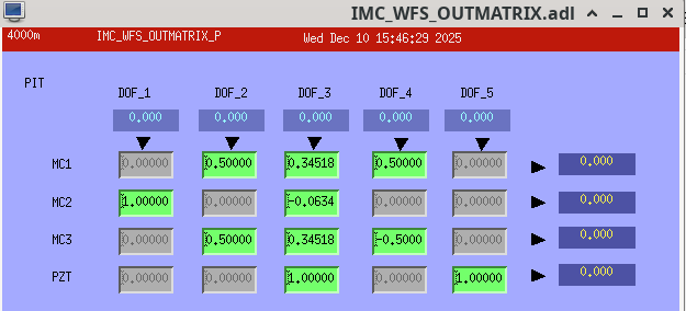
Details for the IMC: We have added a line to the output matrices of the IMC (old P and Y in medm) where the final fifth line is used to send signals to the new JM3 tip-tilt which will be installed in HAM1 during the vent downstream of the JAC and upstream of the IMC, these currently contain zeros in the fifth line but I haven't updated the medm screen for IMC_WFS yet. The ASCIMC model now contains send PCIe modules whoch correspond to the recieve modules in the SUS-JM3 model.
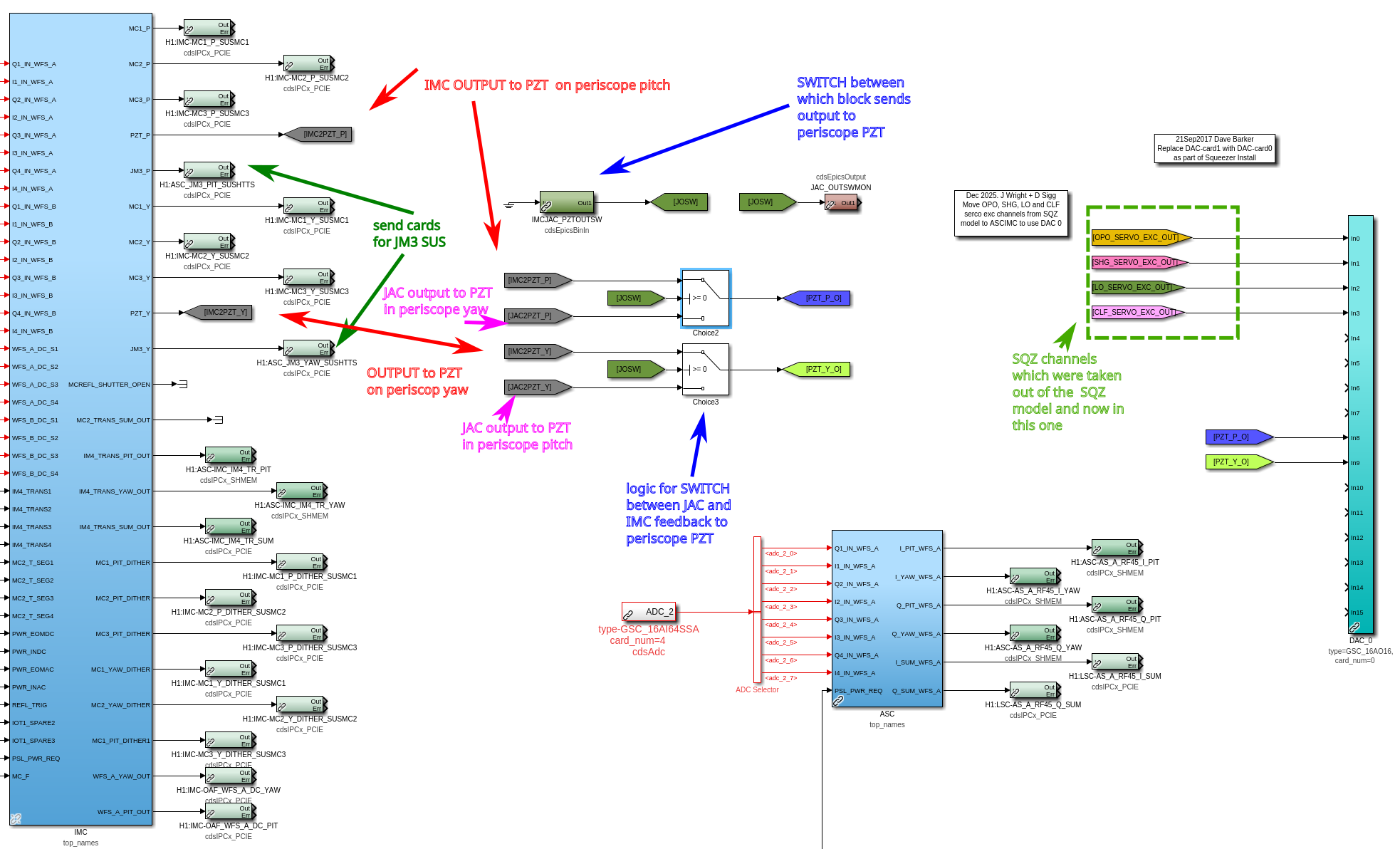
There is also a switch H1:ASC-IMCJAC_PZTOUTSW in the top level of the ASC IMC model to switch between the JAC servo using the periscope PZT as a feedback path (switch OFF) and the IMC servo using the PZT as a feedback path (switch ON). This has been saved in safe SDF snap file in the ON state which means the IMC should work as expected until we have the JAC installed.
I have uploaded a pic here and here of the changes made to the top level in H1ascimc.
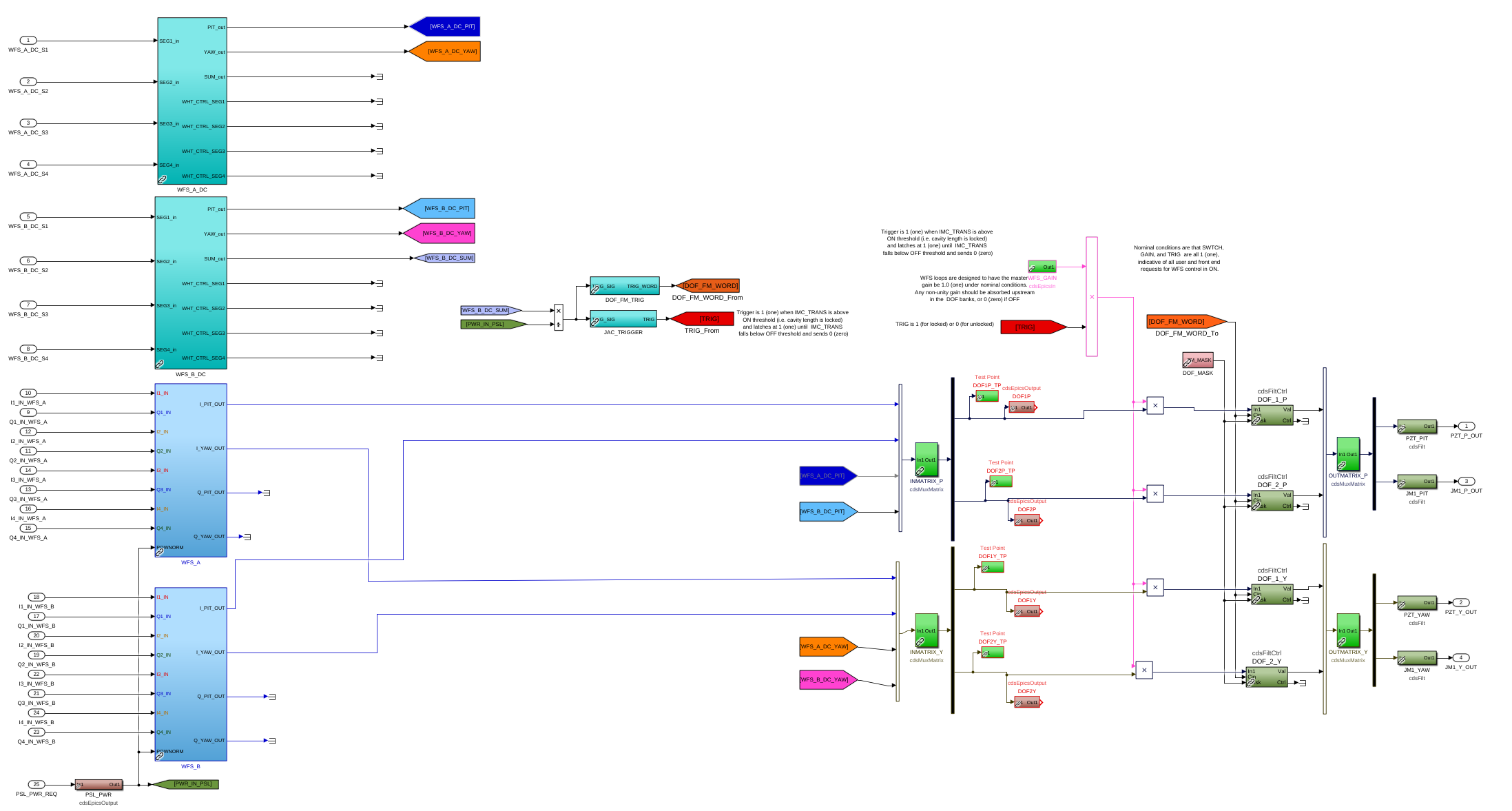
Details for the JAC ASC: In the JAC top_names block we have the attached architecture. This has standard library blocks for the A and B JAC in-air WFS and the DC readouts of each these.
The controls are copied from the IMC model but with 2 degrees of freedom instead of 5. I have also skipped the dither locking controls as we don't seem to currently use this in the IMC.
Details for h1sqz model:
Four squeezer channels were added to h1ascimc model and removed from the h1sqz model are:
H1:SQZ-OPO_SERVO_EXC
H1:SQZ-SHG_SERVO_EXC
H1:SQZ-LO_SERVO_EXC
H1:SQZ-CLF_SERVO_EXC
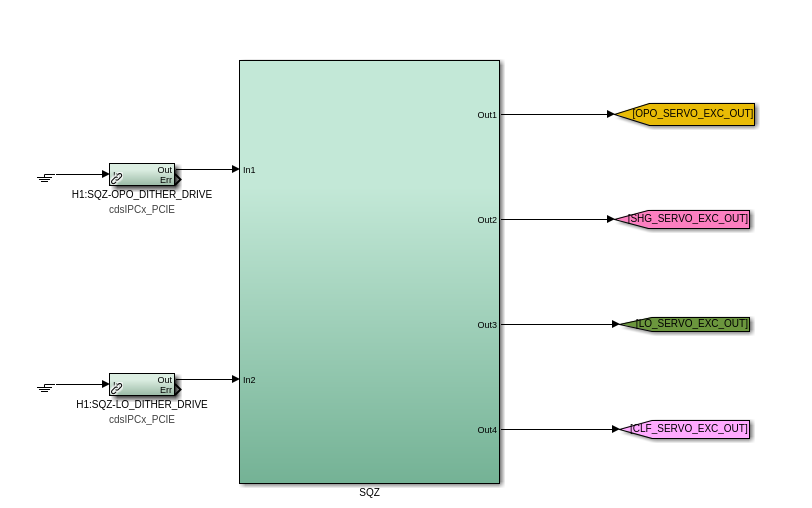
- two are sent from the SQZ model, H1:SQZ-OPO_DITHER_DRIVE and H1:SQZ-LO_DITHER_DRIVE, they go into a SQZ block.
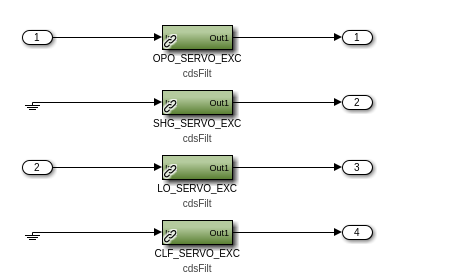
This block contains these filter banks, which we transferred from the h1sqz model. SHG_SERVO_EXC and CLF_SERVO_EXC have grounded inputs like they did the h1sqz model. The outputs are sent to the DAC0 channels highlighted with a green dotted line in this image of the h1ascimc model.