masayuki.nakano@LIGO.ORG - posted 09:23, Tuesday 06 January 2026 - last comment - 12:14, Tuesday 06 January 2026(88691)
PSL mode match lens replacement
[Jason, Jennie, Masayuki]
- We swapped and installed three new lenses—IO_MB_L1 (Rc = 250 mm), L2 (Rc = −150 mm), and L3 (Rc = 750 mm)—replacing the existing lenses with the same notation. The former two are 1″ diameter lenses, and the latter is a 2″ lens. All lenses were mounted in Newport lens mounts, with posts and post holders installed on Thorlabs BA2 bases.
- Set the power stage to 2 W with 100 W of PMC output. The power along the path where the new lenses were installed was then reduced as much as possible using IO_MB_HWP1.
- Before swapping the lenses, two irises were placed to provide alignment references. The final reference is the set of irises in HAM1; however, the in-PSL iris allowed alignment without external communication and made the process easier. These irises were placed downstream of the existing IO_MB_L2.
- After removing the old lenses, the new IO_MB_L1 was installed such that the distance from IO_MB_M2 to L1 was 0.22 m. The beam was centered on the iris by adjusting the lens position. Subsequently, L2 was installed 6 cm downstream of L1 using the same procedure.
- After alignment, we verified that the beam path around the beam adjustment stage was not clipped by any optics. All beam positions appeared nearly identical to those before the work began.
- The third lens was then installed between IO_MB_M4 and M5 (the bottom mirror of the periscope) with a separation of 9 cm. To ensure the lens was centered on the beam, we centered the iris on the beam reflected from IO_AB_BS1 before and after installation. To observe the transmitted beam from M4, higher power was required; therefore, IO_MB_HWP1 was rotated to increase the EOM output power to 4–5 W.
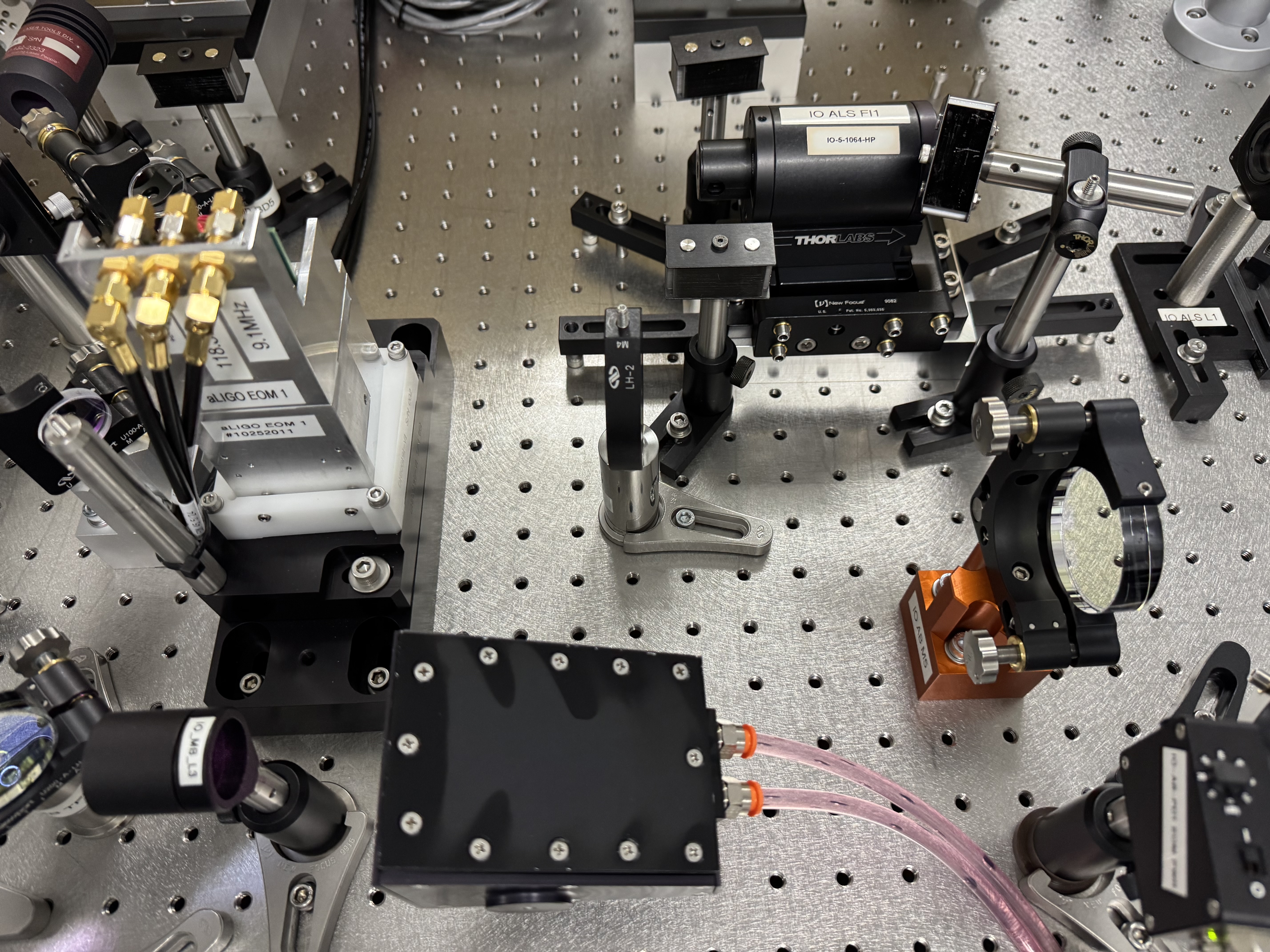
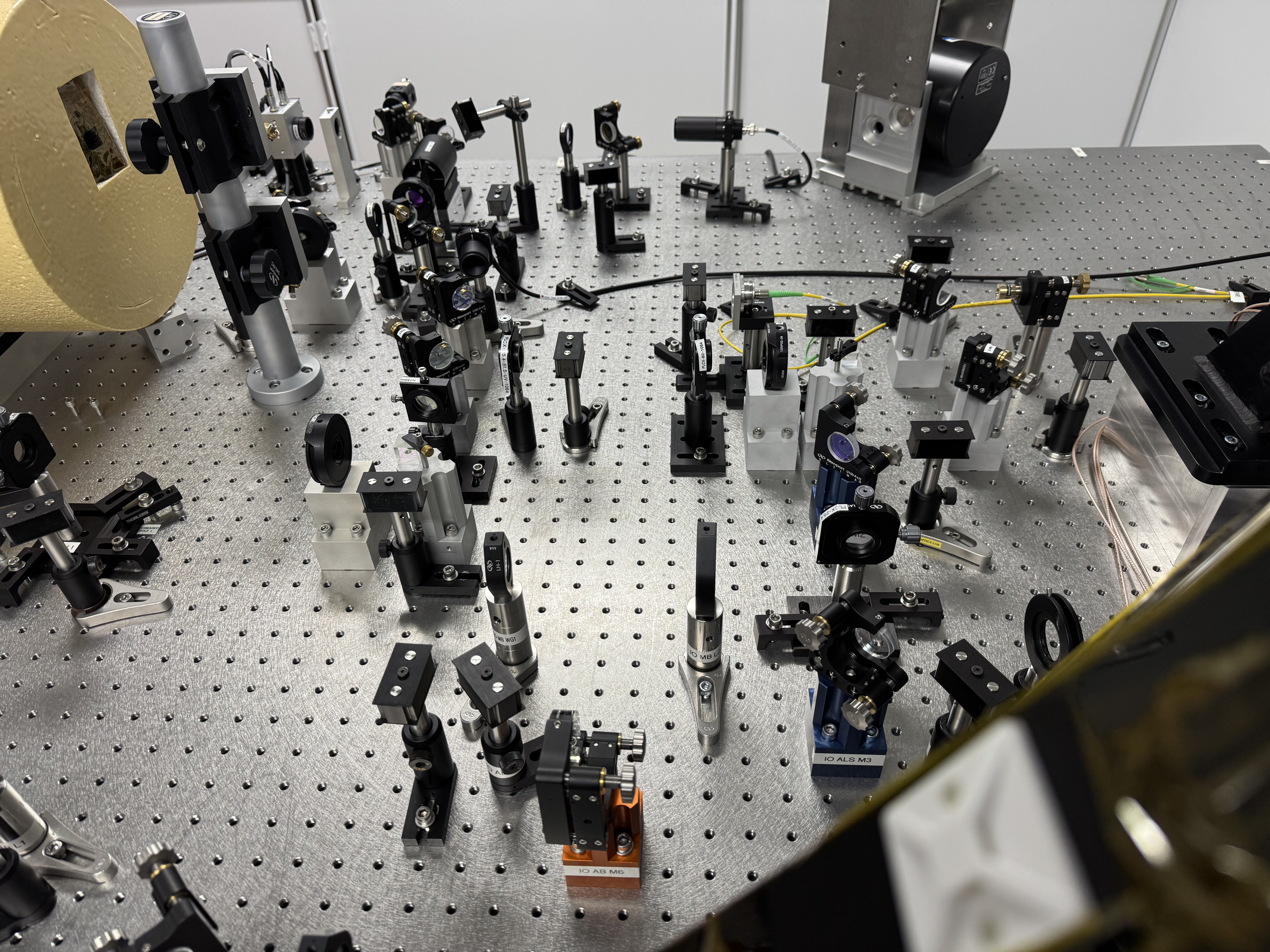
- The first and second pictures document the original lens positions, in case recovery of the mode matching directly to the IMC is required.
- After completing the work, all power levels were restored. During this period, the new lenses were inspected with an IR viewer to confirm the absence of unusual stray light or unintended beam exposure.
- Remaining work: alignment of the photodiodes monitoring the EOM output and PSL output. Since the overall beam profile has changed, it may be necessary to reposition the lenses to properly focus the beam onto the PDs.
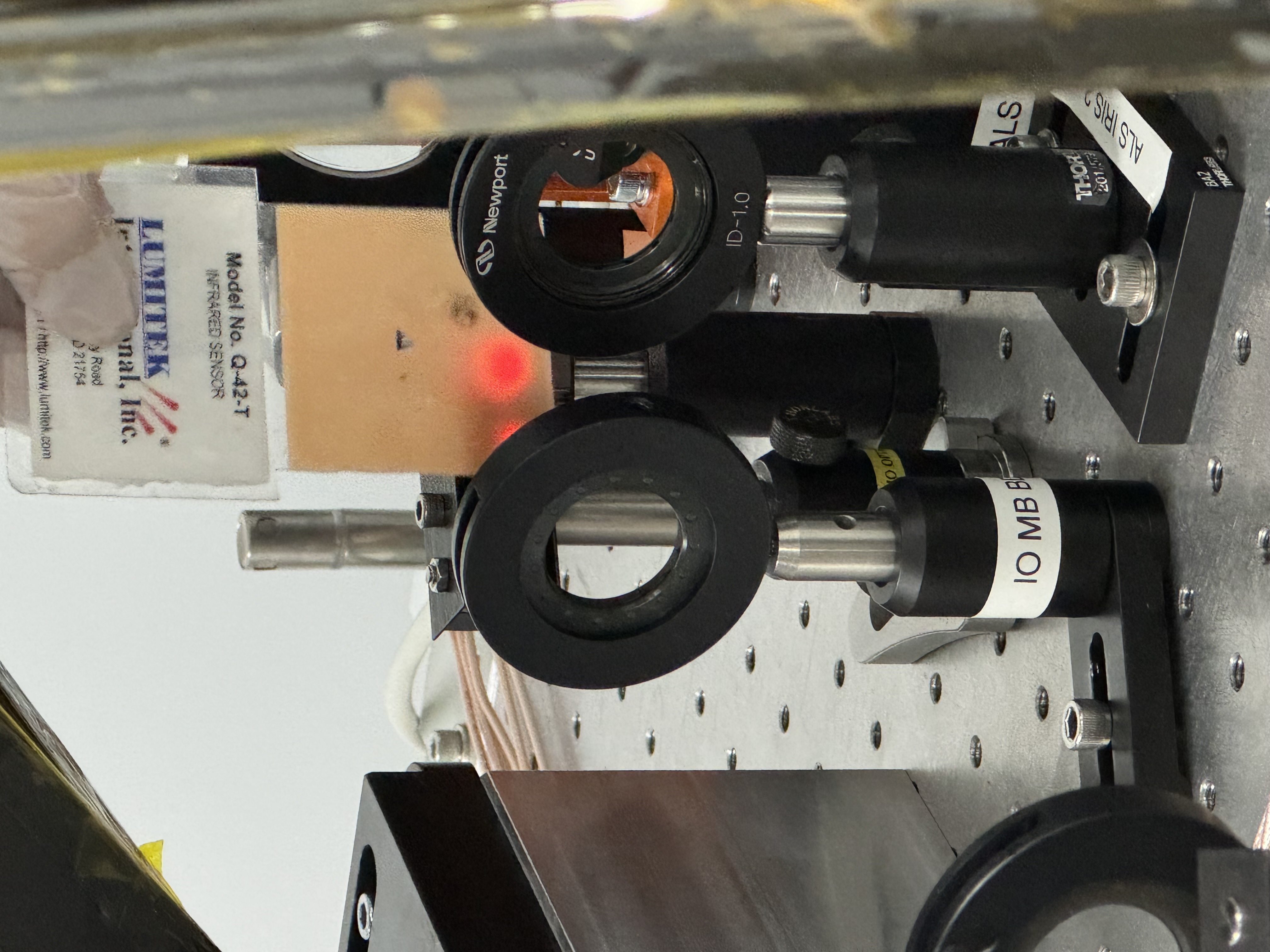
- During the work we found the beam is almost clipped on the beam dump capturing the mispolarized beam difracted by the EOM. So, we move the beam dump. The third picture shows this beam dump.
Images attached to this report
Comments related to this report
Tagging for EPO