[Jason, Rahul, Jennie, Betsy, Masayuki]
Summary
JM1 was swapped from a tip-tilt suspension to a fixed Siskiyou mount to improve beam stability for alignment, profiling, and JAC control. Mode matching to the JAC was measured using a beam profiler, yielding <1.5% mismatch in both axes, well within the current requirement. The JAC pedestal and body were installed in HAM1, and initial beam injection showed clear HoM resonances at the transmission port. One discrepancy in body mode damper mounting holes was identified and will be tracked via FRS.
Details
-
After discussion, we decided to replace the JM1 tip-tilt suspension with a fixed Siskiyou mirror mount. This provides easier alignment, beam profiling, and more stable JAC control compared to using a suspended mirror. As reported in the previous alog, JM1 had already been aligned to the target irises with a good angle, so the position of the JM1 suspension was marked with dog clamps to allow easy recovery of the alignment after installation work. The Siskiyou mount was aligned using the same target irises.
-
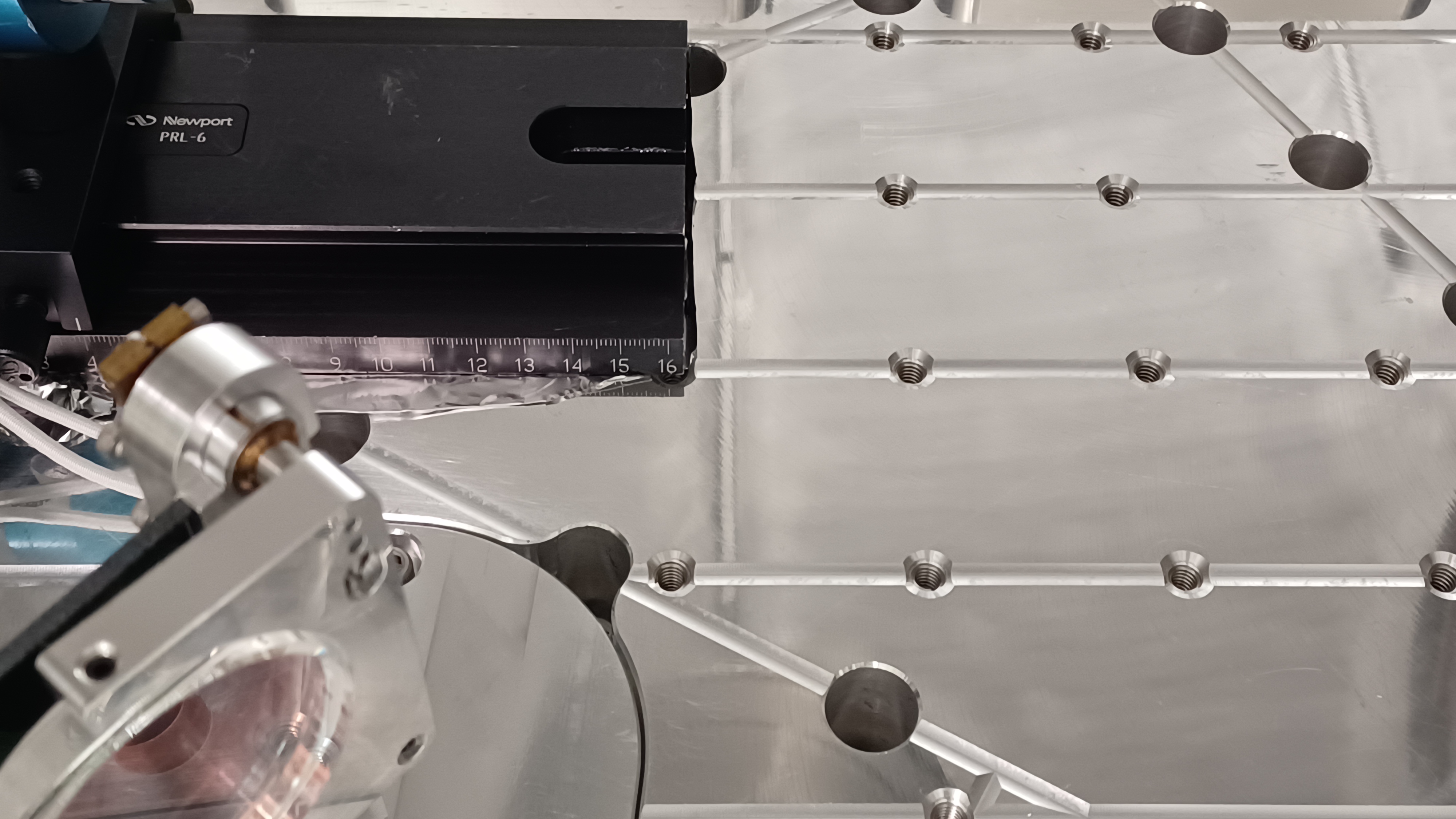
After switching the mirror mount, a beam profiler was set up in the reflected beam path from the fixed JM1 to measure mode matching to the JAC, as shown in the attached picture. The z-origin was defined at the position where the beam profiler cart reading was set at 16 cm along the rail. Due to cable length limitations, beam size measurements near the waist were not possible, but this was not considered a significant issue.
-
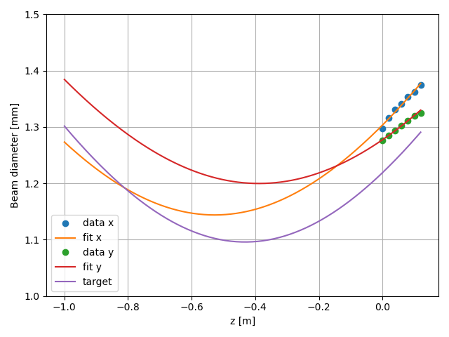
The measurement results are shown in the attached plot. The target and measured beam parameters are:
-
w0_target = 548.00 µm, z0_target = −4.318e−01 m
-
w0_x = 572.01 µm, z0_x = −5.277649e−01 m
-
w0_y = 603.50 µm, z0_y = −3.736913e−01 m
-
-
The resulting mode mismatch was 1.363% (x) and 1.455% (y). Our current target for mode mismatch is 10%, which is sufficient for achieving a reasonable JAC lock. Therefore, this result is excellent and no further adjustment is required at this stage. Fine tuning may be performed later after JAC lock, possibly after HAM1 pump-down.
-
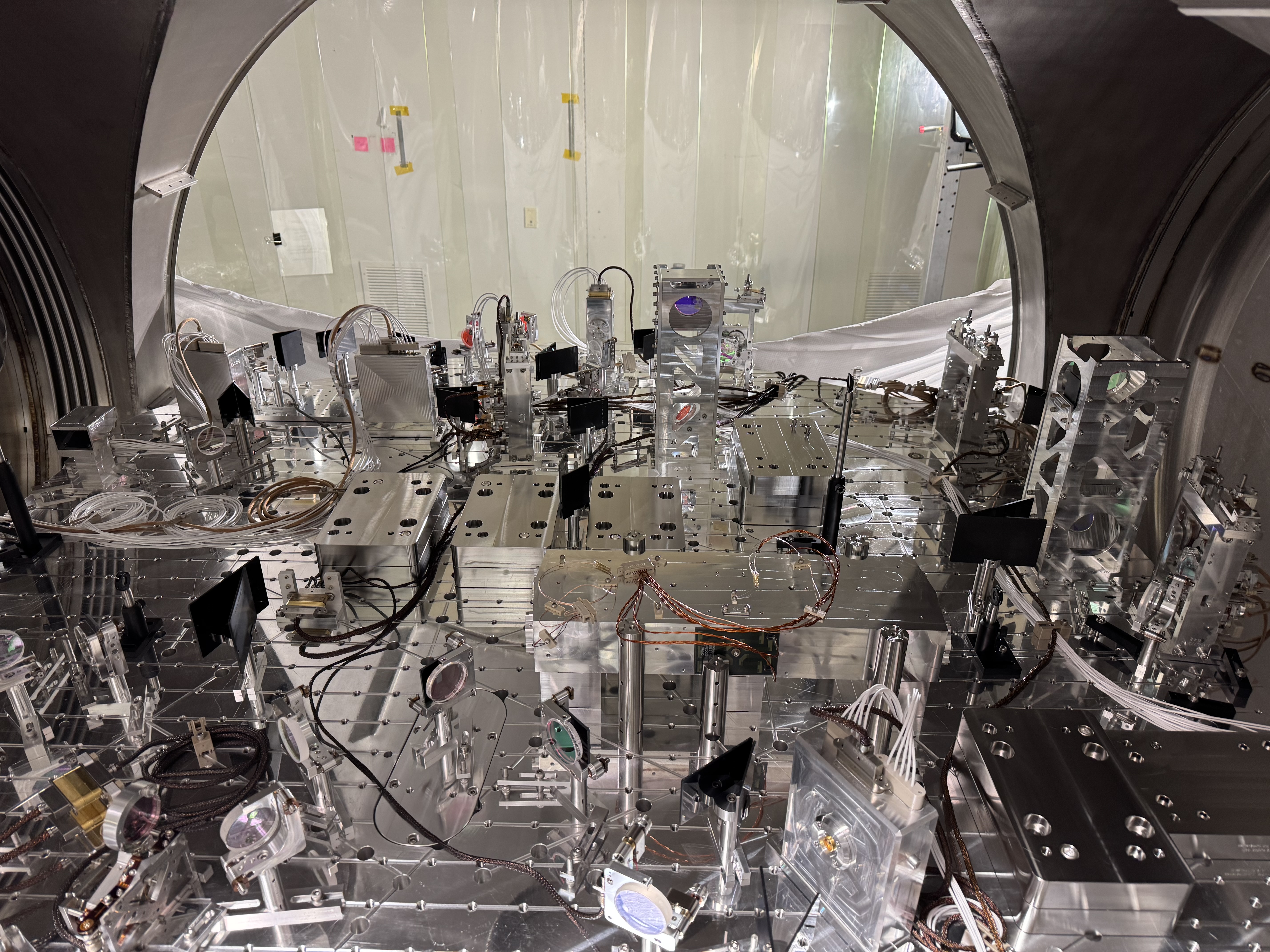
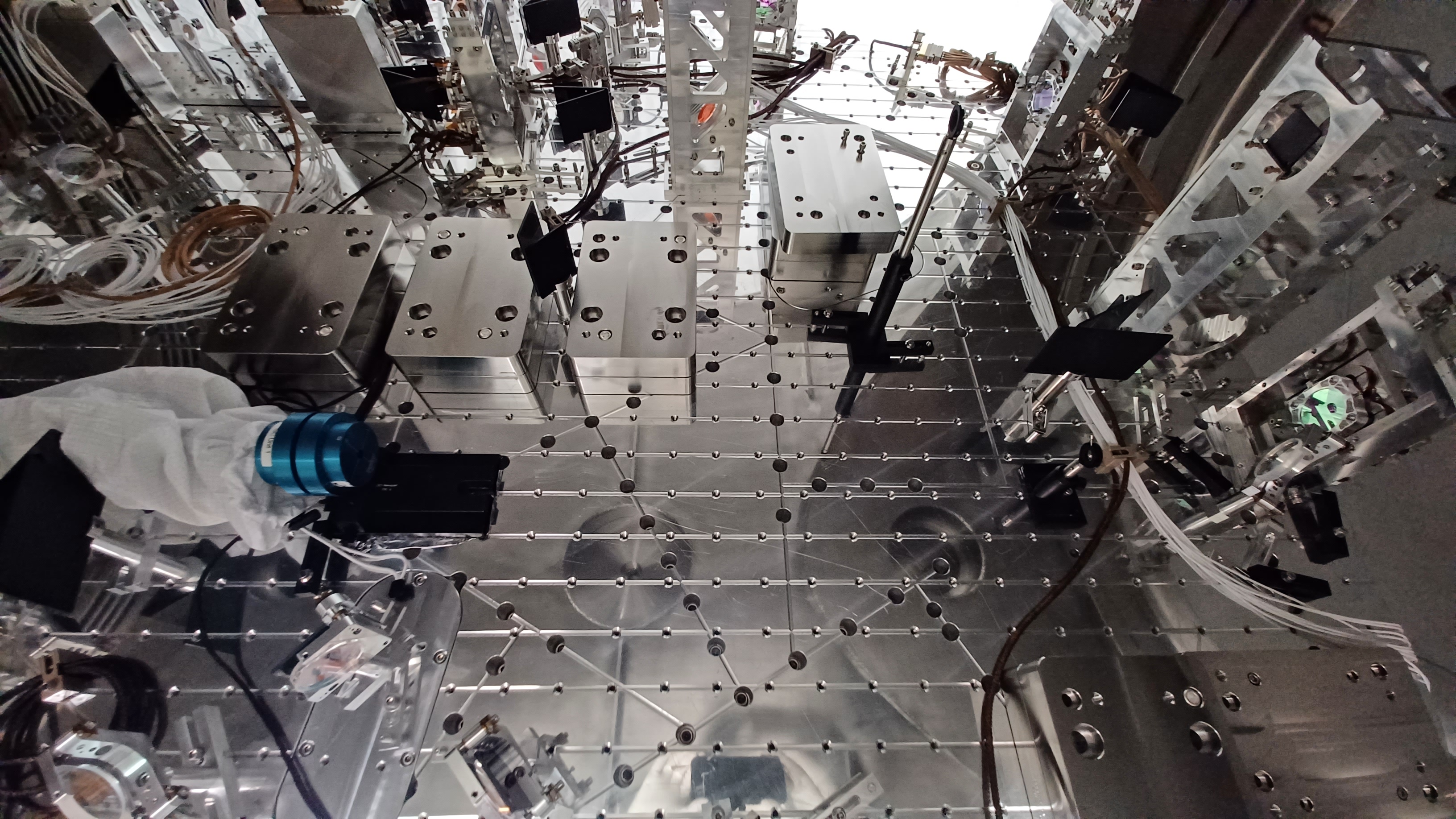
The JAC pedestal was installed and secured to the table, and the shim was placed on the pedestal.
-
The JAC body was then brought into the chamber. The procedure was recorded on video. A handle (not Class-B cleaned) was temporarily attached to the JAC; it was wiped down, and aluminum foil was inserted between the handle and the JAC body. During installation, Jason and Rahul supported the body from the sides while I handled the lift into HAM1. The end caps protecting the mirrors remained installed throughout this process.
-
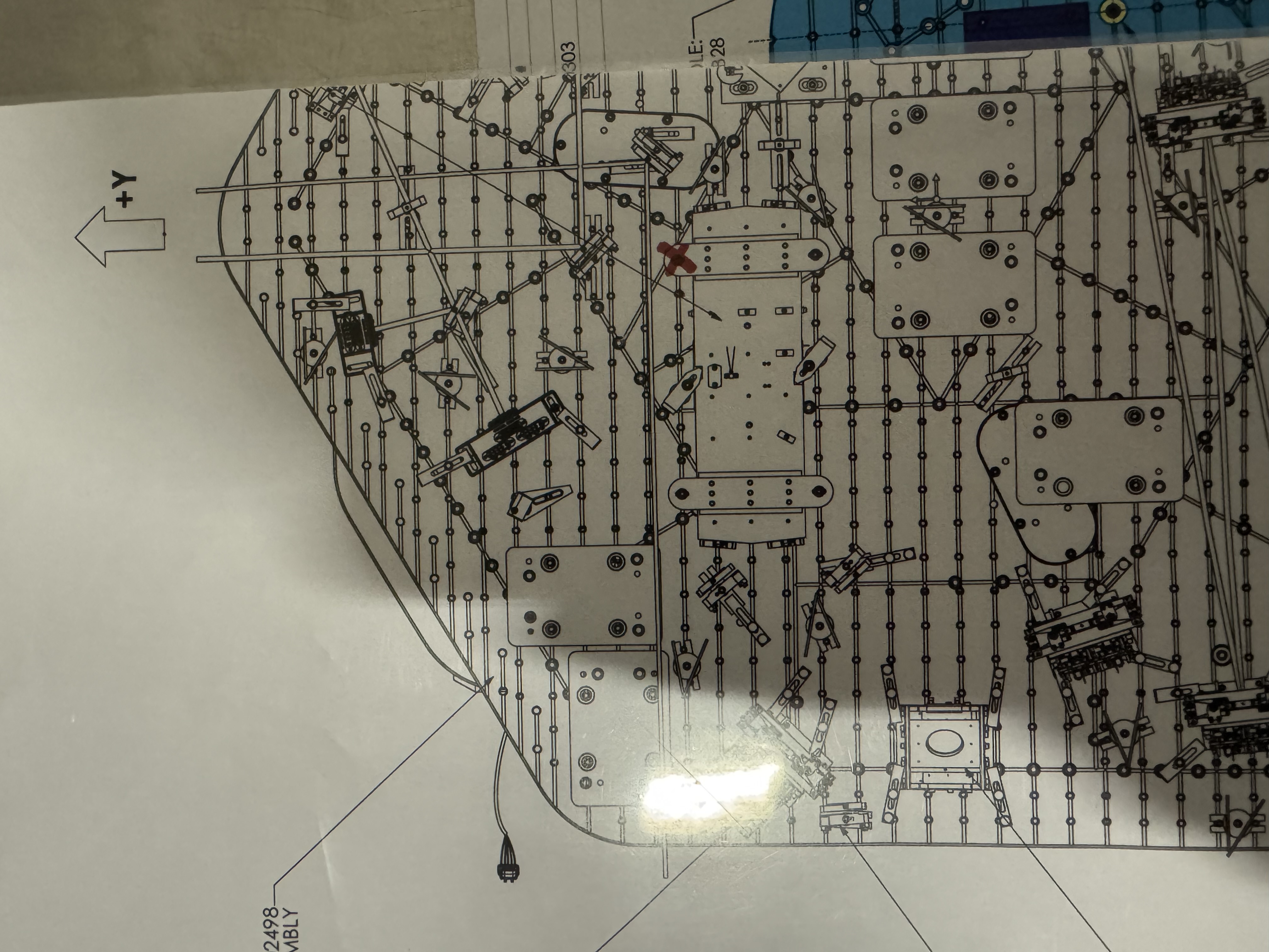
During installation of the body mode dampers, we found that one of the screw holes specified in the drawings was missing. The location of the missing hole is shown in the attached picture. As a result, one body mode damper was shifted by one column of screw holes (a 2″ offset). We discussed this with Stephen and believe it should not cause an issue, although it will be monitored. An FRS ticket will be submitted to track this discrepancy.
-
After removing the end caps, the beam was injected into the JAC for a quick alignment check. A higher-order mode (HoM) resonance was immediately observed at the transmission port, confirming successful initial alignment. The next steps are fine alignment of the input and reflected beams, followed by in-vacuum wiring.
I attached the photos of the readout from the nanoscan with the first one being the beam size at the front of the rail, second labelled zero is at zero of the rail, and the others are labelled with the position on the rail in mm.


