We have identified two mechanical issues with the JAC EOM and its mount.
Issue 1. Crystal isn't captured in the EOM assembly when we install it in a certain way, but installing it in another way to capture it might (or might not) put overly strong force on the crystal.
No I haven't dropped the real crystal, I did drop alumina piece with the same outer dimensions as the RTP crystal while testing the installation procedure.
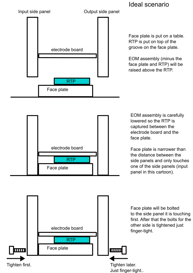
It's probably hard for you to understand this issue if you're not familiar with the EOM assembly (D2500130) and the assembly/test procedure (google doc), look at my super-simplified cartoon (ideal.png).
EOM comprises the face plate, RTP crystal and everything else. Everything else is already assembled. The task is to sandwich the RTP between the electrode board (which is a part of "everything else") and the face plate. You'll put the face plate on a table, put RTP on top of the face plate, carefully lower everything else until the board touches the RTP along its entire length, and you bolt the face plate to the side panels. Simple.
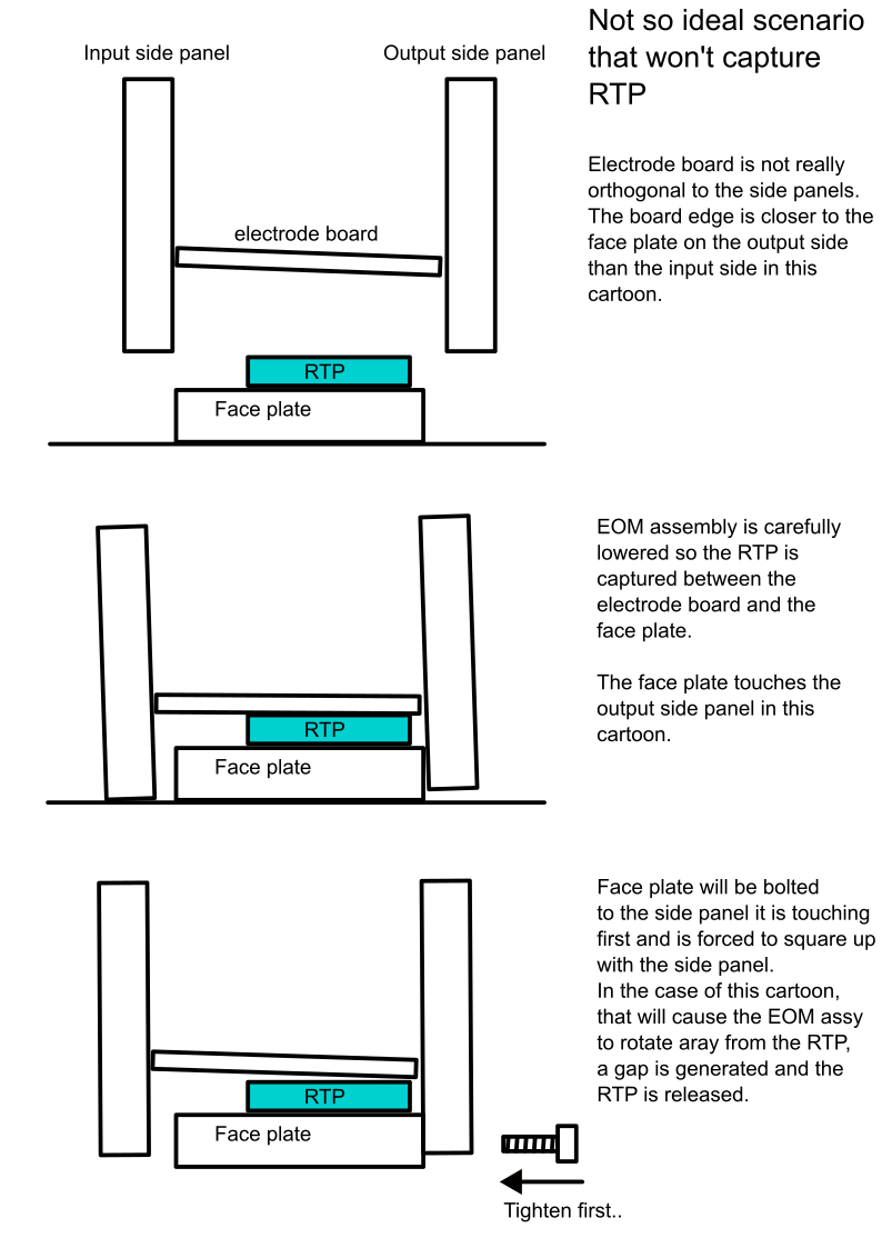
It can be much different from that if the board is not orthogonal to the side panels, look at the second attachment. Here, the board is crooked, the distance to the face plate on the output side is smaller than on the input side (this cartoon).
Suppose that I choose to make the face plate contact with the output side plate, and bolt the face plate down. The face plate is squared up relative to the side plate, not the board, and the "everything else" part will rotate away from the face plate (or face plate rotates away from everything else) and RTP is free to move. I think this is what happened consistently (10 or so trials) in the lab today, no matter what we did, the alumina piece (i.e. fake RTP for excercize) slid out of the assembly but only after tightening the screws.
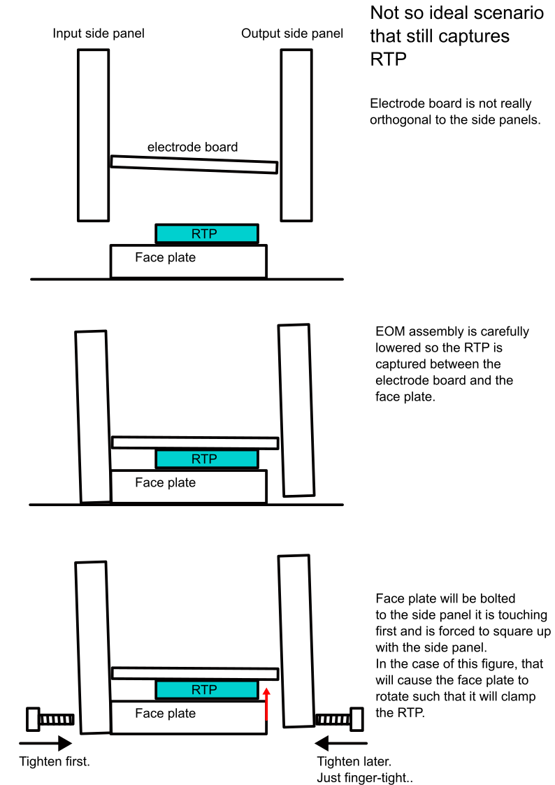
On the other hand, if I choose to make the face plate contact with the input side plate (notsoideal.png), the rotation will be in the opposite direction, the face plate is not reqlly squared up but will put a pressure on the RTP, securely captureing it. After switching the side where the face panel contacts in the lab, the alumina piece (fake RTP) never dropped (3 trials so not much statistics but 3/3 success is much better than 10/10 failure).
The problems are that we don't have any control over how much force is applied to the crystal. Moreover, in our "successful" trials, the board might not be touching the alumina piece along its entire length. Look at the picture, this is after the last (3rd) "successful" attempt with the alumina piece still in, the board and the face plate are not parallel with each other, we might be pinching the alumina thing at the corner closest to the output side. Not sure if it's always like this but it's likely.
Stephen and Michael suggest that instead of bolting the face plate firmly to the input side, there could be a gap on each side, the face plate is supported by the tension of the screws, making sure that the face is parallel to the board. I'm not necessarily a fan of the idea but we'll try.
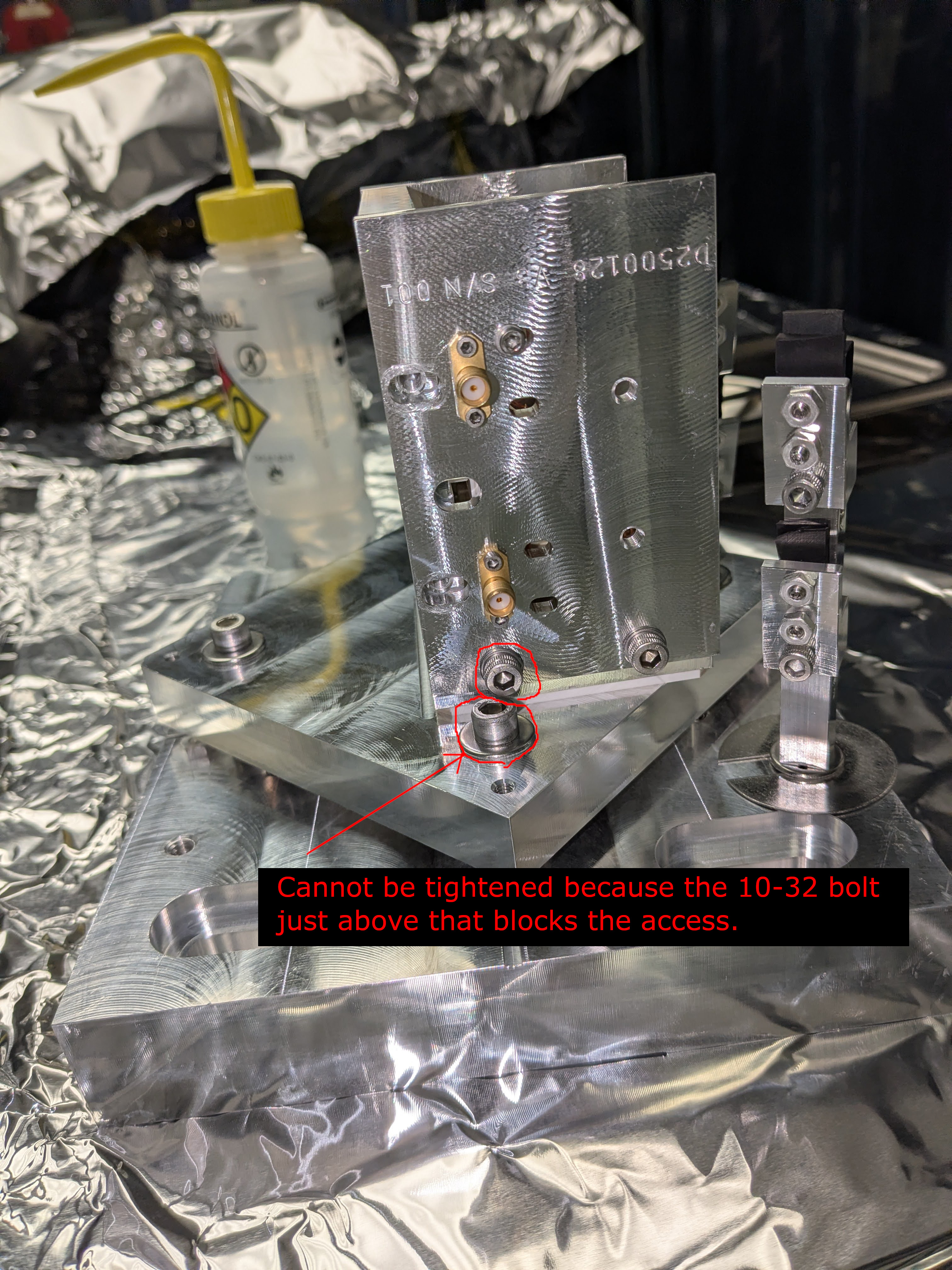
Issue 2. One of the bolts for the EOM base is blocked by another screw head.
See the last picture. One 1/4-20 screw cannot be tightened because the 10-32 bolt head just above that blocks access. We might replace the offending bolt with 10-32x0.375" pan head screw AND use the ball head Allen key for 1/4-20, that might work.
Other issues.
We can move the mount in PIT/ROLL and YAW, but somehow it's very difficult to cause pure PIT motion, it always couples to ROLL.
When we use set screws to tilt the base and then back them off, the mount won't return to the original position, I have to push down the pivot plate toward the base plate firmly, then there's a metal clicking sound and the mount goes back. This might be related to the fact that, as of now, the dowel pin (part #14 of the assembly drawing) is a REALLY tight fit for the pivot plate as of now.
Finally, the cable strain relief post could not be set at a desired angle using the supplied slotted washer (the only difference I was able to make is either bad angle or 180 degrees off of the bad angle). But using other washers on top of the slotted one(s) I was able to manage good-ish angle.


Another potential mechanical issue (?).
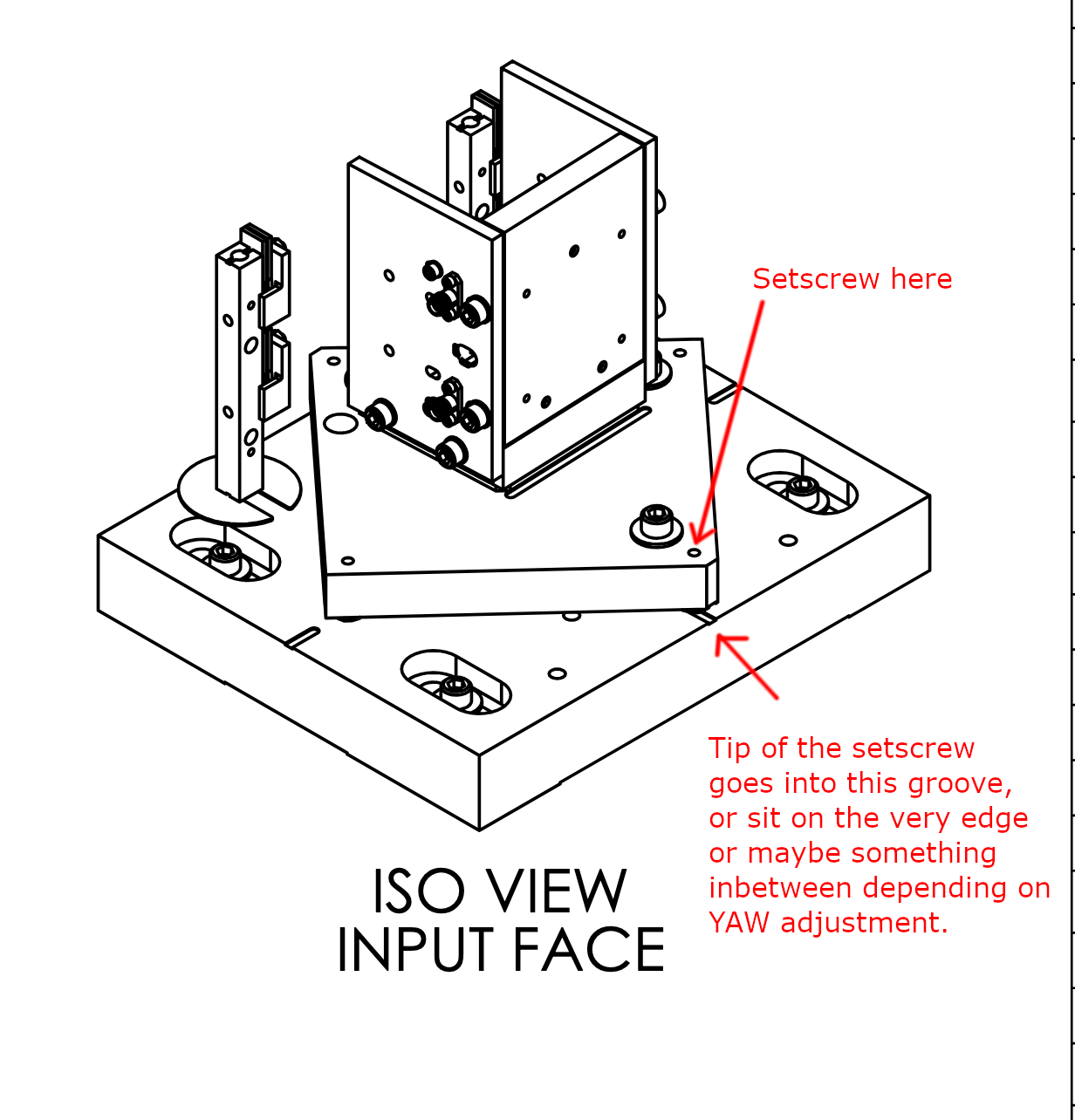
One of the roll adjustment set screw (8-32 oval point) is riding on top of the shallow groove that is 0.125" wide and 0.02" deep in the base plate. Depending on the YAW adjustment, the round tip of the screw might sit on the edge of the groove, making things unstable. FYI the standard diameter of 8-32 screw is 0.164" so it's wider than the recess, I don't know the exact profile of the oval point but the YAW adjustment range of this mount is smaller than it seemed at first to me.
If the groove is just a visual aid, maybe it can be shortened such that it won't interfere with the set screw.
I couldn't take a good picture of this, if I can I'll post it later.