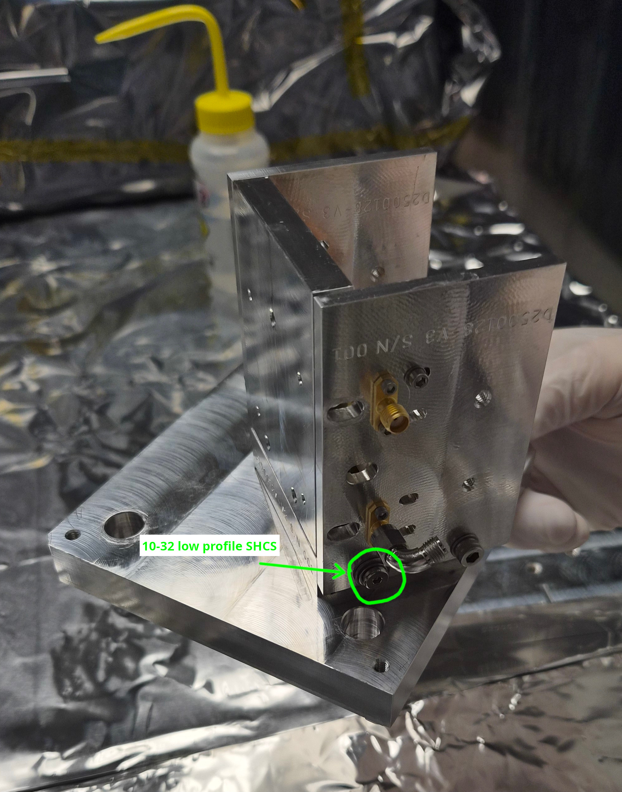
10-32x0.375" SHCS that was blocking the access to one 1/4-20 screw was replaced with a low profile 10-32 SHCS.
"Issue 2" in alog 88862 was solved.
See picture, Mitch found a 10-32x0.5" SHCS with a low profile head. 0.5" seemed to be OK in that it's not too long, but we used two washers to make sure that the scrwe doesn't bottom out.
EOM crystal mounting practice part 2 (with a remote help from Michael)
Summary:
- "Laxen method" (no gap between the front plate and the input side, big gap for the output side) was repeated again with an extra caution (see below), no visible gap between the alumina piece and the electrode (with a help of flashlight), alumina doesn't slip out.
- "Appert method" (even gaps for the input and the output) was tried twice, no visible gap between the alumina piece and the electrode, alumina doesn't slip out.
- During Appert method tests we have found that the output side plate might be slightly warped.
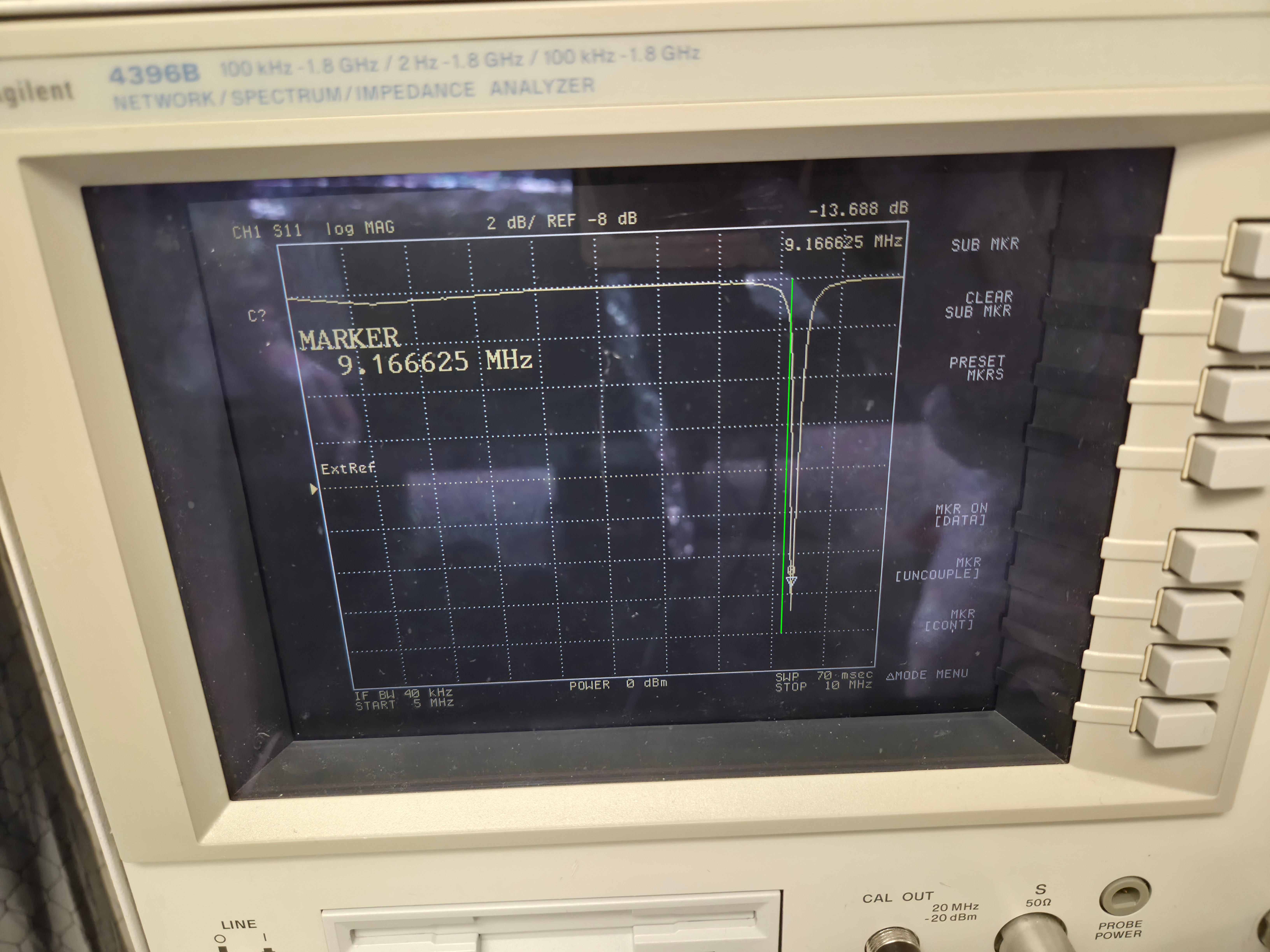
- RF return dips were measured for all three of the above (one Laxen and two Appert mounting method), they were consistent regardless of the mounting method and were consistently higher than nominal with the alumina. (No RTP yet). It goes progressively worse as the frequency goes up. Michael told "The resonant dip needs to sweep across the desired frequency."
- Lower two frequencies (9.1MHz and 24.08MHz) look reasonable in that the nominal frequency is inside the observed dip.
- 45.5MHz dip is just barely on the shallow part of the dip curve.
- 118MHz is the worst, the nominal frequency is totally out of the dip (1MHz off).
- Michael suggested that the capacitance for the elctrorode-crystal is too small but we (Matt and I) couldn't see any light coming through the supposed gap.
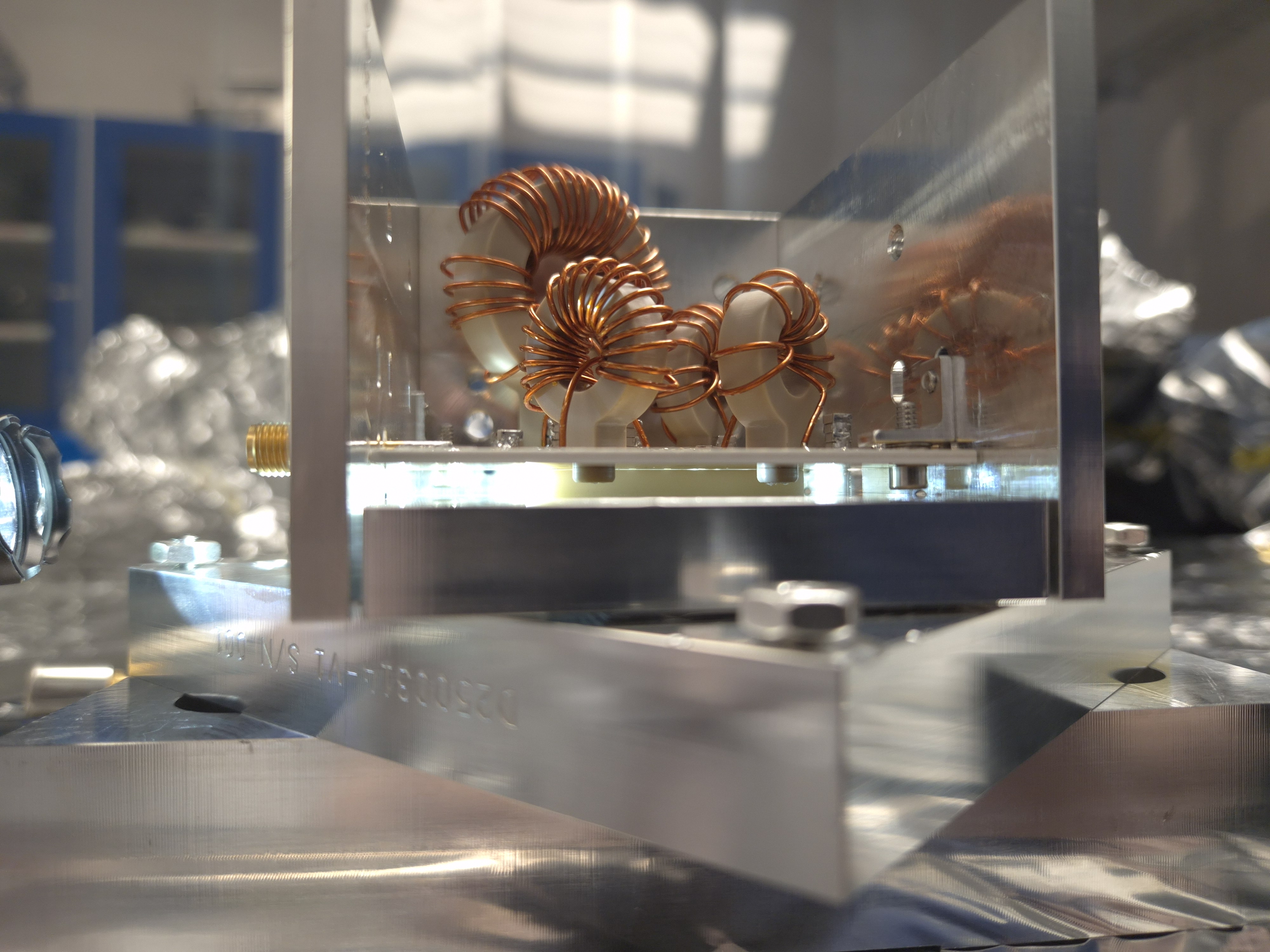
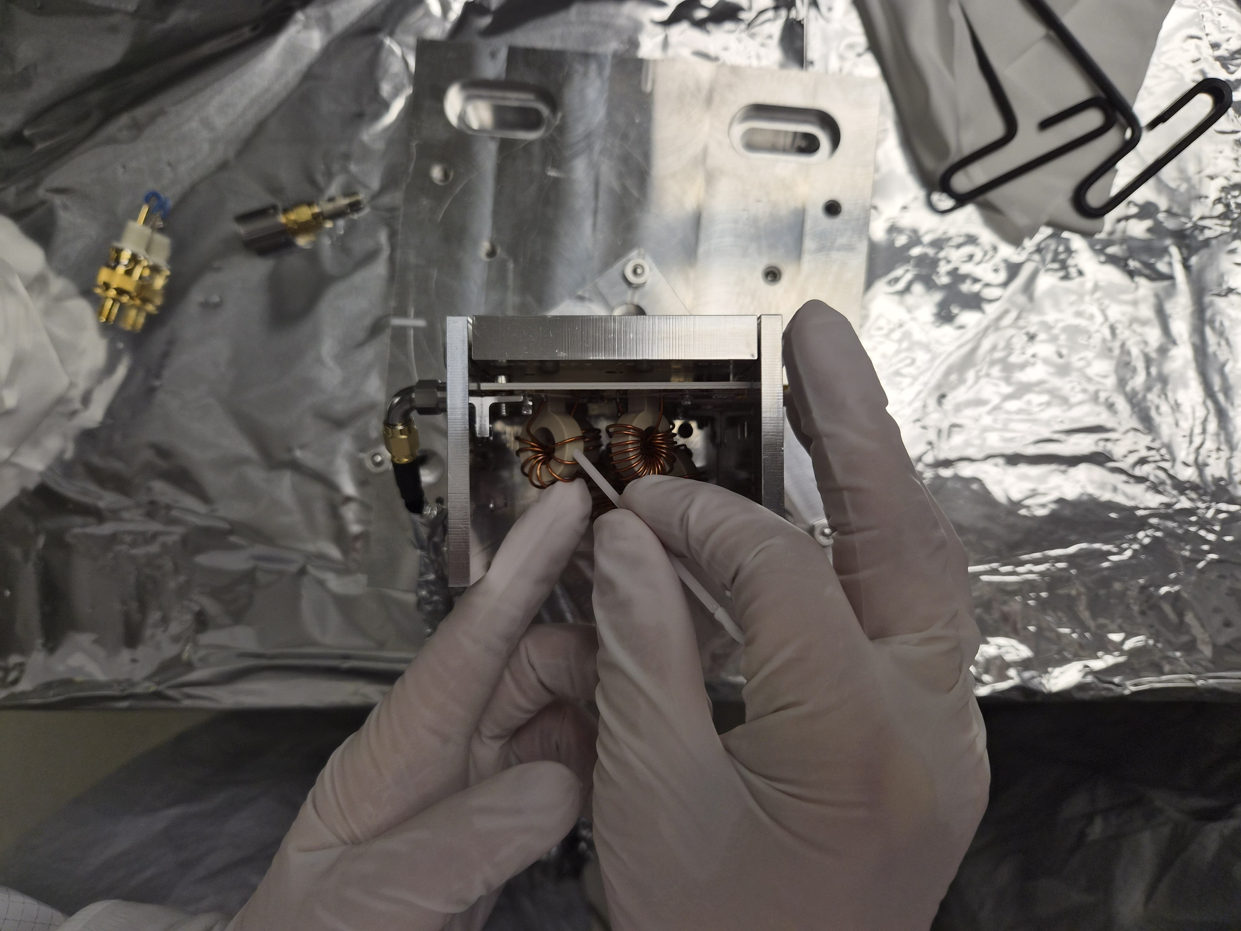
- Michael also suggested that the windings of the inductor coils might have been bent (got looser) during shipment.
- I tested bending the coil windings for 118Mhz inductor so they come closer together and it had a huge impact. I was able to easily come close to a reasonable frequency, but it's no good unless we know that the capacitance for the crystal-electrode is OK. I haven't changed trim cap nor touched any other frequencies.
- I'll measure the peaks without the alumina on Monday. Will discuss further with Michael, Stephen and Gabriele (while Masayuki is traveling to here).
Laxen method test.
In alog 88862 we left the EOM module with the alumina piece mounted using Laxen method (no gap between the input side plate and the front plate, a big gap for the output side).
Shining flashlight into the iput or output aperture in the side plates is useful to see the gap between the electrode plate and the alumina piece, and we found that there was indeed a small gap only on one side (i.e. the "crystal" was pinched at the edge).
I loosened the screws for the face plate and repeated the mounting procedure, but this time being extra careful to tighten the screws by tinier amount (than my previous attempts) at a time while applying a gentle pressure from the top. As soon as I got much tighter than finger-tight, I stopped. This resulted in what was seemingly a good contact between the alumina and the electrode, no light visible between them.
See nogap.jpg, this is a representative picture of GOOD contact (even though I cannot prove that the contact is really plane-to-plane not just plane-to-one edge of the crystal).
Another picture gap.jpg is an example of BAD contact. It's hard to see but there's no gap at either edges closer to input/output faces, the gap is only in the middle. I don't have a good explanation for this.
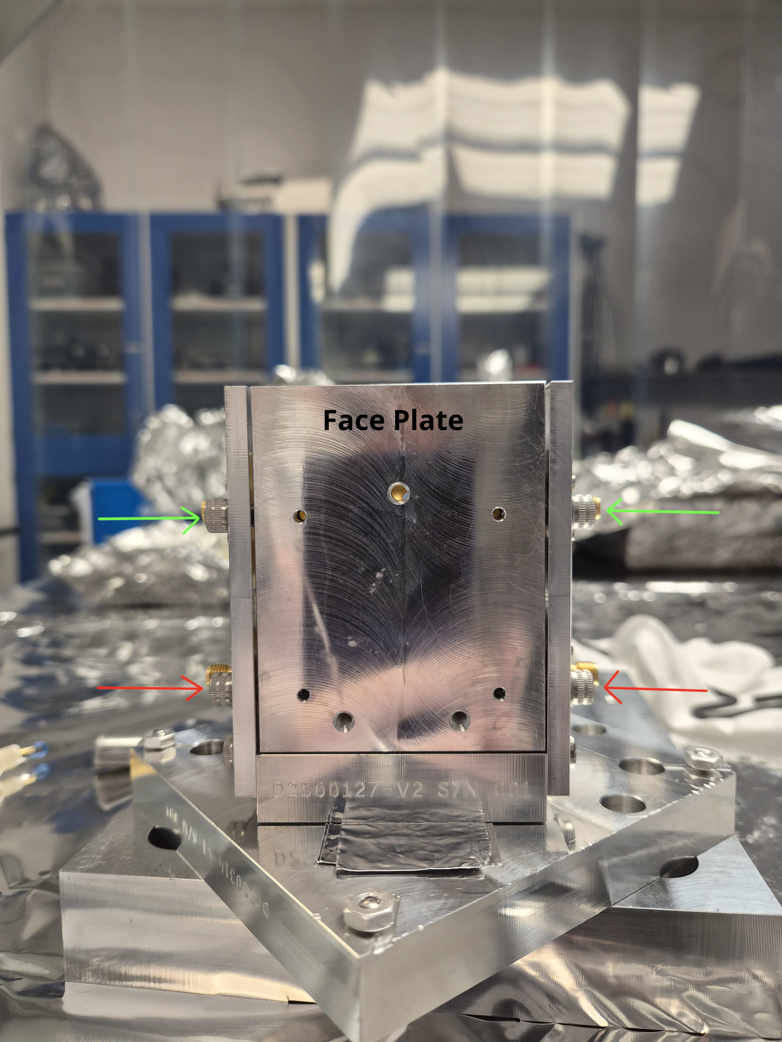
Appert method tests.
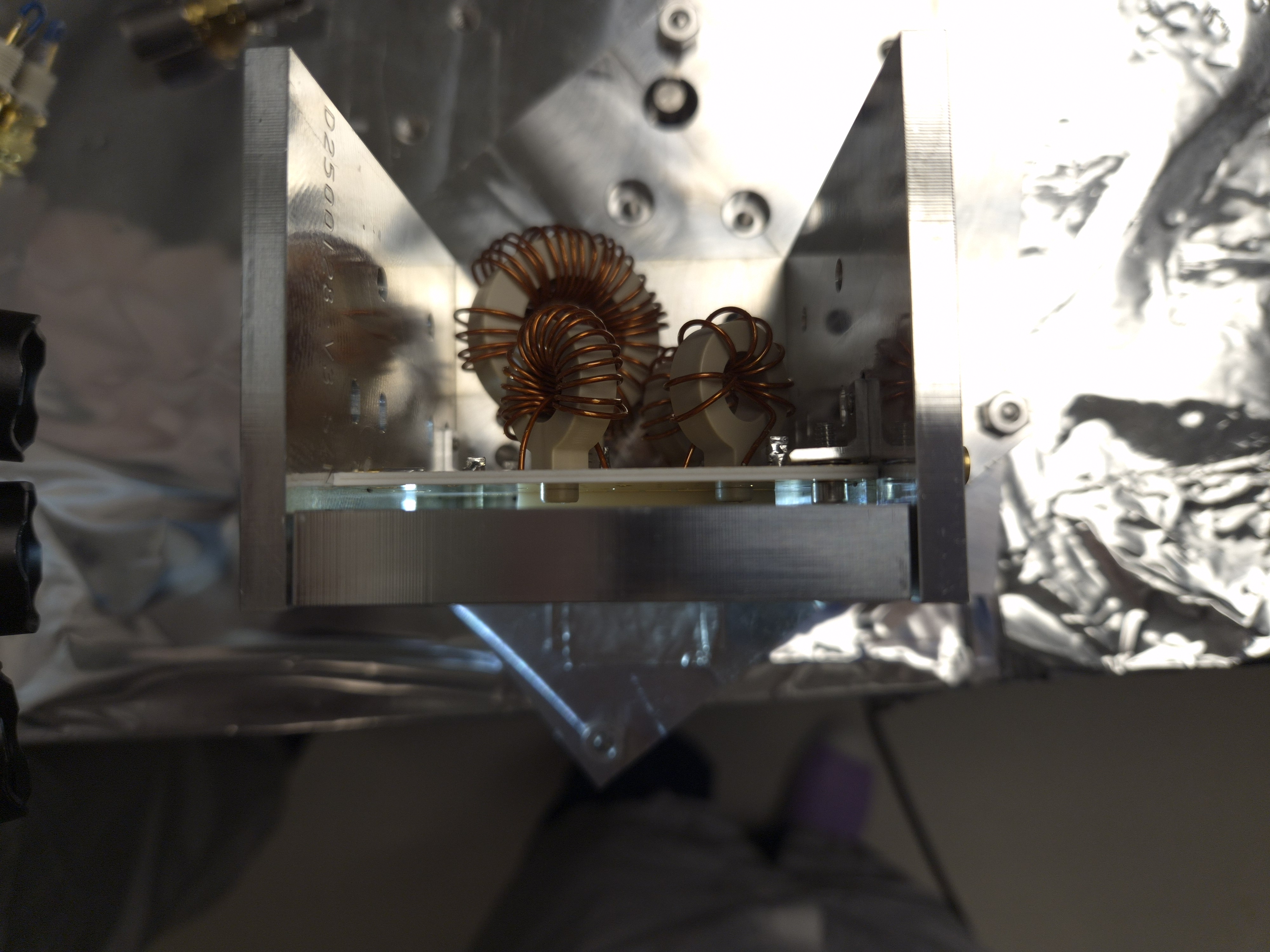
We also tested Stephen's suggestion to make a gap on both sides of the front plate. This was trickier but doable by using two Allen keys. The third attachment (EOMassembly.jpg) shows the EOM placed on top of the EOM mount parts just for picture AFTER the alumina was mounted. During the mounting process, the face plate is facing down, and two allen keys will tighten two screws with green (or red) arrows in the picture with tiniest rotation at a time. Green, red, green, red, repeat it until it feels reasonably tight but much, much looser than you'll usually do for tight mechanical connection. After this was done, neither Matt nor I were able to undo the screws by finger.
We did this twice, both times no gap between the alumina and the board, and alumina didn't slip out.
Output side plate might be warped?
In the assembly picture, can you see that the gap between the face plate and the output side panel (right on the picture) is uneven, but the gap for the input (left on the picture) is fairly even? I don't think this is an optical illusion. This might be related to the reason why the crystal ALWAYS slips out when the face plate is tightened down to the output side plate, see my alog (88862). Quoting myself, "no matter what we did, the alumina piece (i.e. fake RTP for excercize) slid out of the assembly but only after tightening the screws". Maybe it's the output side plate.
Reflection measurement.
For each of the above three practices (one with Laxen method, two with Appert method), S11 coefficient was measured for all four ports.
What we found was that all four reflection dips were higher than they are supposed to be. According to Michael, alumina should give us similar results to RTP. I don't list results for all three sets (3x4=12 numbers) because numbers were pretty consistent across the sets, maybe give or take 10kHz or so.
| Nominal LHO/LLO (MHz) | 9.100230 / 9.099055 | 24.078360 / 24.078 | 45.50115 / 45.495275 | 118.30299/118.287715 |
| Measured (representative number) (MHz) | ~9.17 | ~24.10 | ~46.05 | ~119.8 |
In the attached pictures, green line is roughly where the center should be. 9.1 and 24.08 look reasonable to me. Not sure about 45.5MHz, it's 450kHz off. 118.3MHz is totally, totally off.
As I wrote in the summary, I tried bending the coil windings for the 118MHz (bendandsqueeze.jpg) because it was the worst but also because it was the one with the loosest of all four coils (118MHzWinding.jpg), and it had a huge effect. With just a few rounds of bending/squeezing I was able to go down to 118.53MHz (afterbending_118MHz.jpg). I could have passed 118.3 and gone to the other side easily but I stopped there.


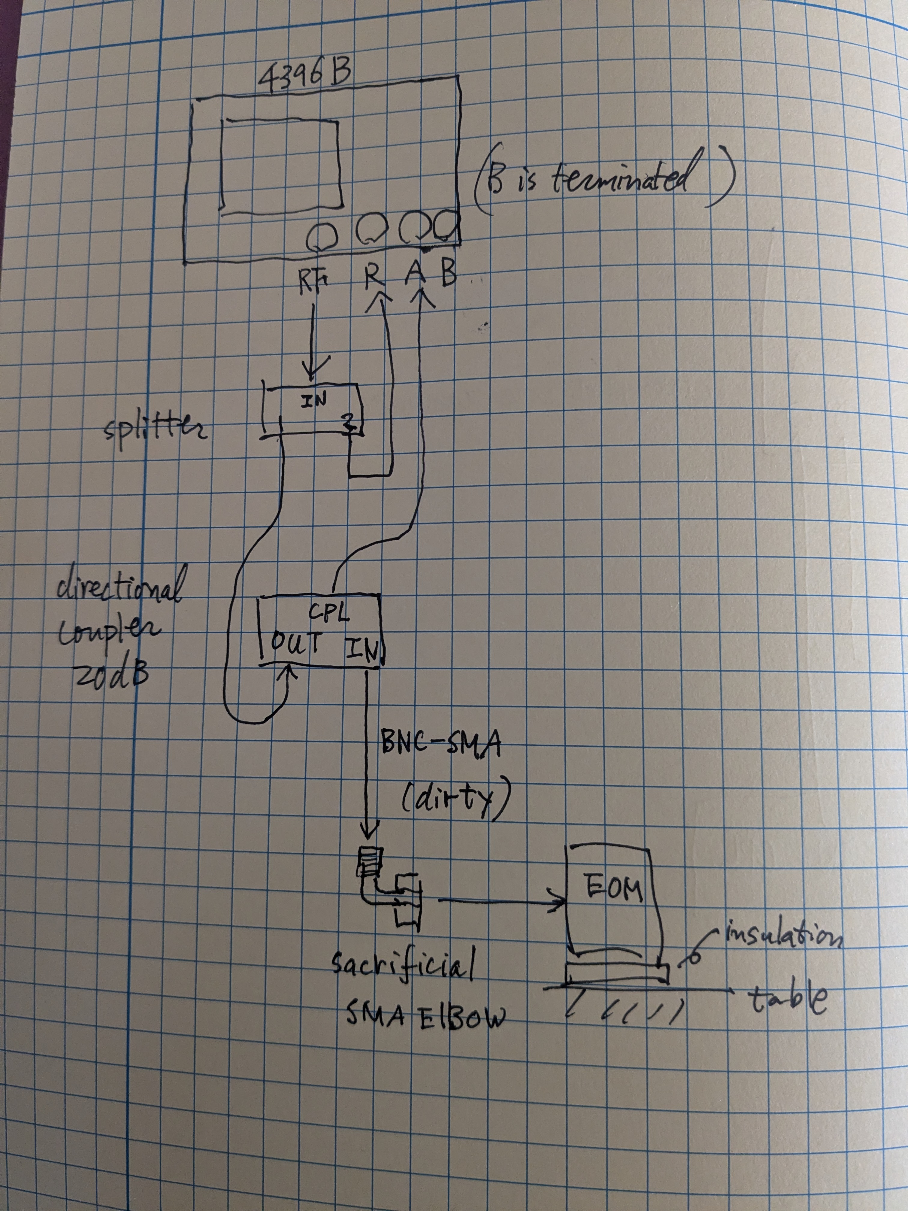
Just in case somebody else must do this, here's what I did to measure S11 (reflection coefficient).
If you go to the optics lab, everything is already set up like in the attached cartoon except that the dirty cable is removed from the coupler and placed on top of the optics table. You might still do the calibration again (because we turned off the analyzer at the end of the day and I cannot remember if the calibration results are kept in the analyzer). Remember that EOM is class A but your cables are dirty (even though we wiped the connectors of the dirty cable using q-tips and IPA). We're using one sacrificial SMA elbow that used to be class A to connect your dirty cable to the EOM.
Anyway, calibration. Set the frequency range to whatever you want but make sure that it covers the frequency range of main interest, like at least 9MHz to 125MHz or so while performing S11 calibration.
Connect the BNC of the dirty cable to the INPUT connector of the directional coupler, like in the attached cartoon.
Press "cal" button and select S11 calibration. Don't connect anything to the SMA of the dirty cable and press "Open" button. Next attach a hand-made short circuit plug to the dirty cable via BNC male to SMA female connector. Press "Short". Then connect a 50Ohm SMA terminator to the dirty cable via SMA barrel. Press "Load". Then press "Done".
Now you're done with calibration. Press "Measure" and make sure that you're measuring S11.
Clean the SMA with IPA and q-tip again. Connect the dirty cable to the elbow, and the elbow to the EOM. Set the frequency range to whatever you want. That's it.