[Keita, Jennie, Masayuki]
Summary
After completing the EOM alignment, we realigned the beam to the IMC using JM2 and JM3. During this process, a large shift of JM3 was observed and corrected. By iteratively moving JM3 toward the PSL side, the mode mismatch was improved to below 1%. We also confirmed the presence of a diffracted s-polarization beam from the EOM with an angle consistent with expectations. Finally, we measured the power throughput and completed the alignment of the TRANS PD path.
Details
After finishing the EOM alignment, we attempted to align the beam to the IMC using JM2 and JM3. At this point, we noticed that JM3 had moved significantly. We re-tightened the dog clamp and the mirror mount, after which the alignment recovered. The mode mismatch (ratio of 2nd-order mode height to TEM00) after this realignment was 0.93/48 = 1.94%. This is actually worse than we measured yesterday, would be because the EOM crystal clipping was solved and it changed the beam shape.
To further improve the mode matching, we decided to move JM3. First, JM3 was shifted by 0.5 inch toward the PSL side, which improved the mode mismatch to 0.57/41.8 = 1.36%. We then moved JM3 by an additional 0.5 inch, resulting in 0.32/39 = 0.821 %. A further 0.5 inch shift improved the mismatch to 0.25/38.8 = 0.644%. Since this level was sufficient, we stopped the adjustment at this point.
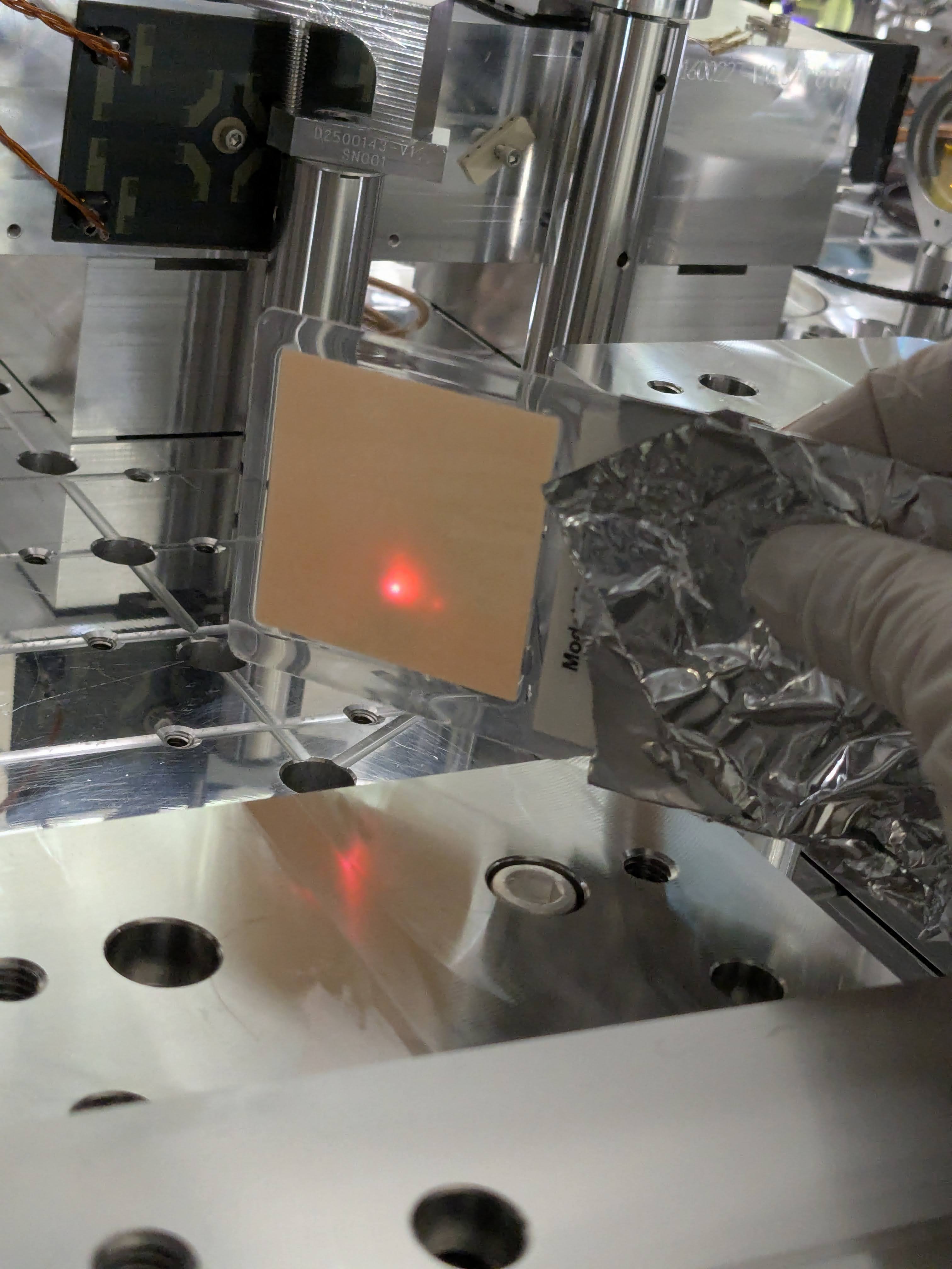
We observed an additional beam separated by approximately 1 cm from the main beam at a distance of about 1 m from the EOM. This is likely the s-polarization beam diffracted by the EOM. The relative angle between the two beams was approximately 0.5 degrees, which is consistent with expectations.
We then measured the power throughput using a power meter. The measured powers were 94 ± 2 mW at the EOM output, 95 ± 3 mW at the EOM input, 7 ± 1 mW at JAC REFL, and 100 ± 1 mW at JAC input which indicates no significant loss.
We also checked the beam position at JM3 and confirmed that it was shifted by approximately 1/4 inch in the +y direction. The iris after JM3 and the iris after the periscope were then centered.
Finally, we aligned the TRANS PD path. Using JACT_BS1, we temporarily installed an HR mirror in place of the laser window to obtain sufficient light to the TRANS PD. With this configuration, we aligned the photodiode such that the reflected beam from the PD was properly dumped into the beam dump. Also, we make sure the transmission beam from the laser window will be cought by the same beam dump by removing the mirror and make sure that the beam coming from the JAC is directly hitting the beam dump.
Pictures:
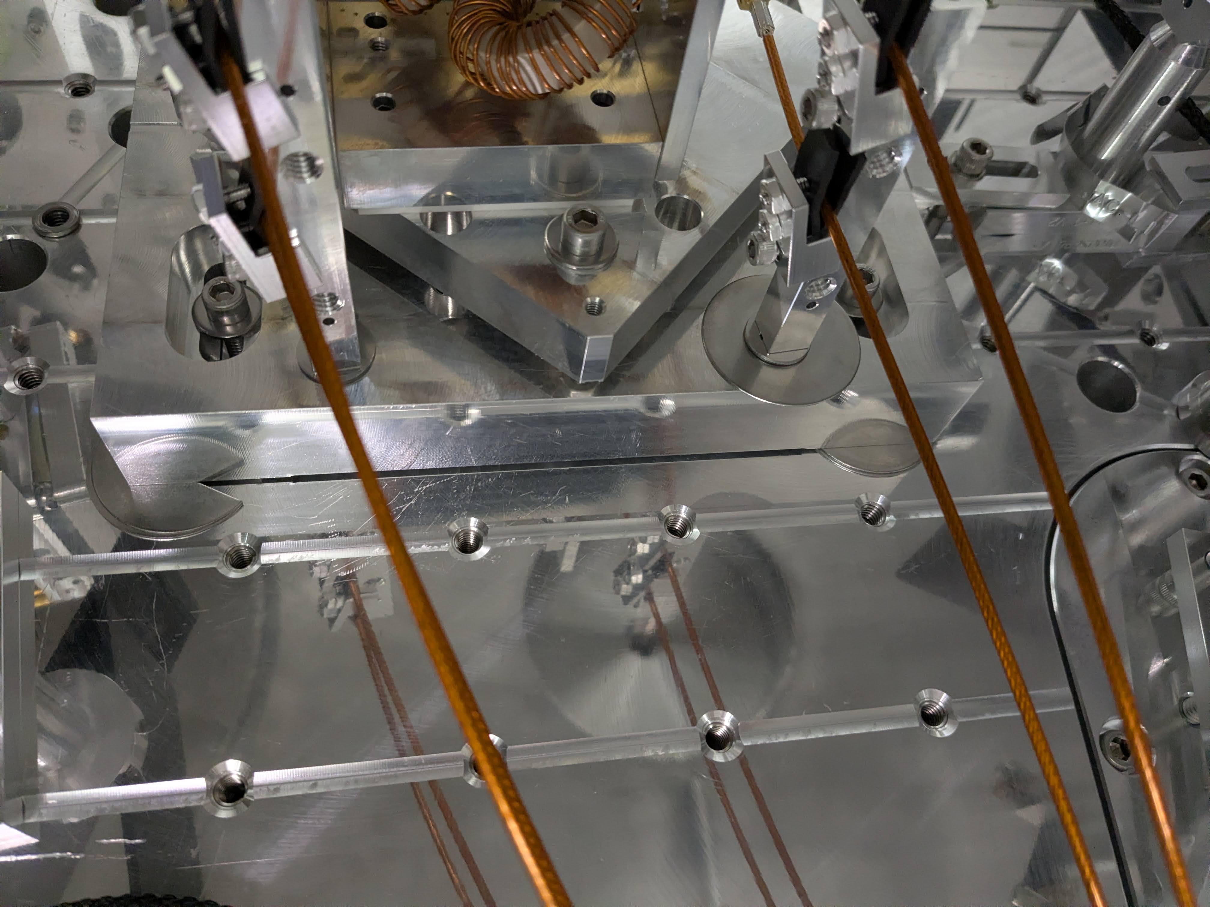
JM3 beam position, JM3 position, and L2 position
The JAC scan gives 0.347(TEM00) to 0.00425+0.0013+0.009= (other small peaks). The total fraction of small peaks is 4%. So, 4mW of the 7mW at the reflection includes all of these fractions.
EOM alignment
This was a 2-day's worth of job. It was briefly reported in the alog from the first day (89018) but I'll repeat what was already reported so people can see what was done concerning EOM alignment in a single log.
Day 1:
After we thought we completed the mode matching yesterday, we found that the beam has a halo that looked like a weird horizontal streak (horizontalstreak.jpg). It seemed as if it came from the EOM itself.
Eventually we found that the beam coming out of JAC looked as if it's higher than the EOM crystal center by more than 1mm (sorry no picture). We raised the entire EOM assembly by about 1mm by inserting shims under the EOM base plate at 3 locations. shims.jpg is the top view of the EOM, see shim_front.jpg and shim_back.jpg for the close up of the shims. (Each shim is actually two 91080A026 flat slotted washers, each washer is 0.02 to 0.026" thick, so the EOM got higher by anywhere from 0.04 to 0.052" or 1 to 1.3mm.)
After this, the horizontal streak was gone but there was still a vertical streak that was hard to photograph. We checked the horizontal beam position on the EOM input aperture and it looked awfully close to what is supposed to be the edge of the crystal (EOM_IN_horizontally_off.jpg).
We pushed the EOM in -Y direction by 1mm or so, the input beam position looked good, we realigned the beam downstream of the EOM, measured the mode matching, that was great and we were happy. But I thought that the beam still looked a bit weird vertically (though better than before), it was better than before but weird. We checked the beam position on the EOM output and it was off (EOM_OUT_horizontally_off.jpg).
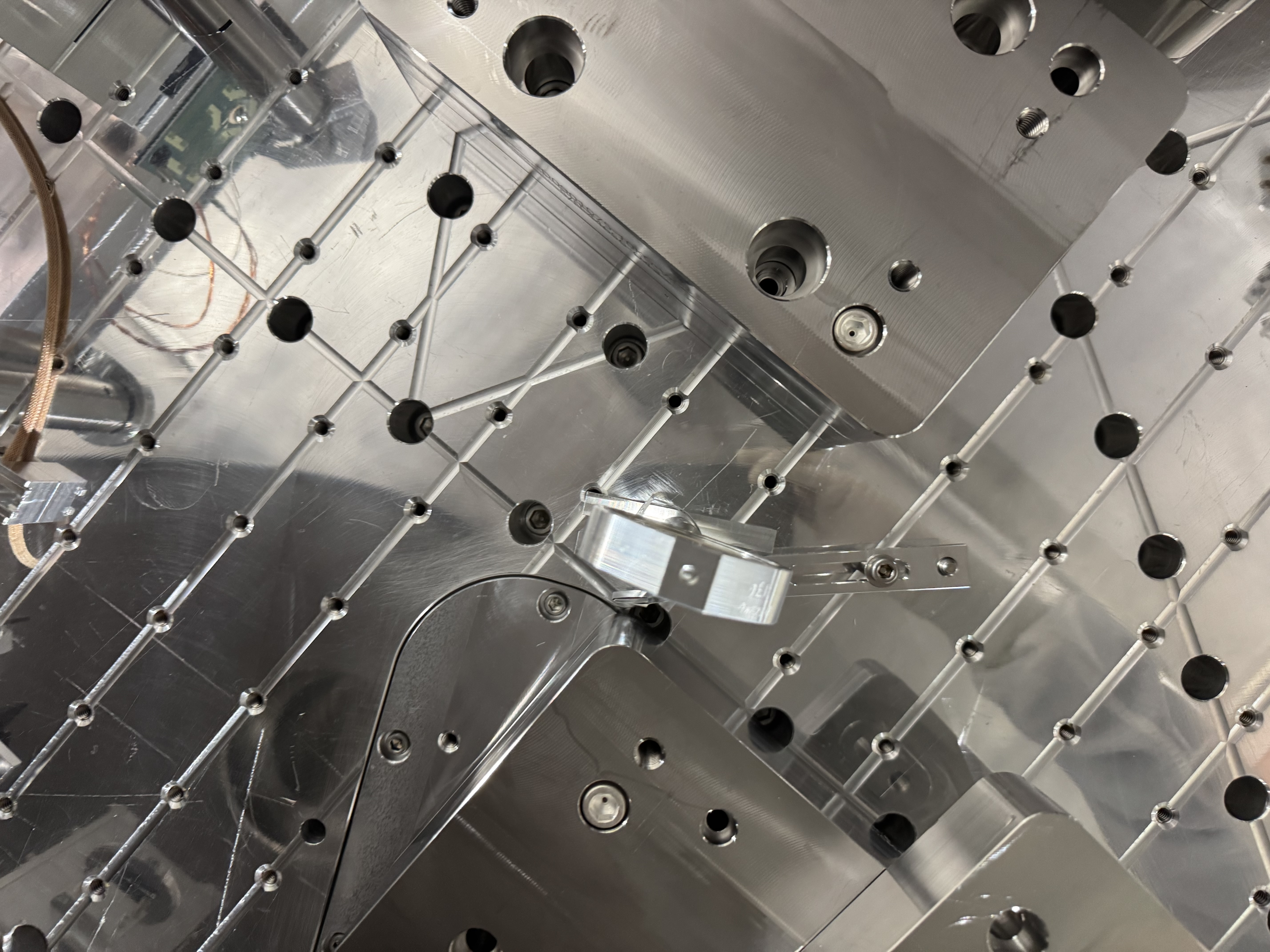
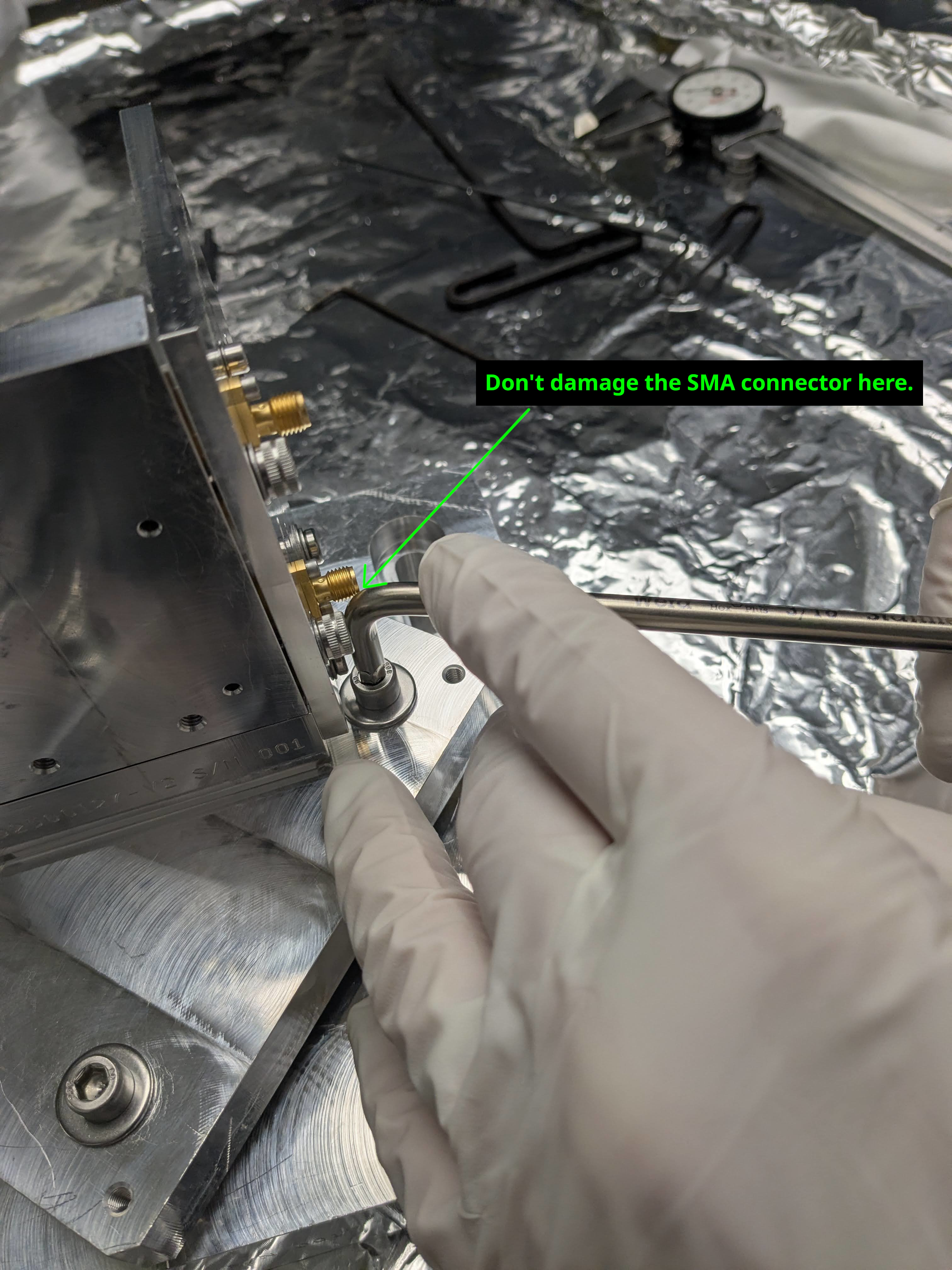
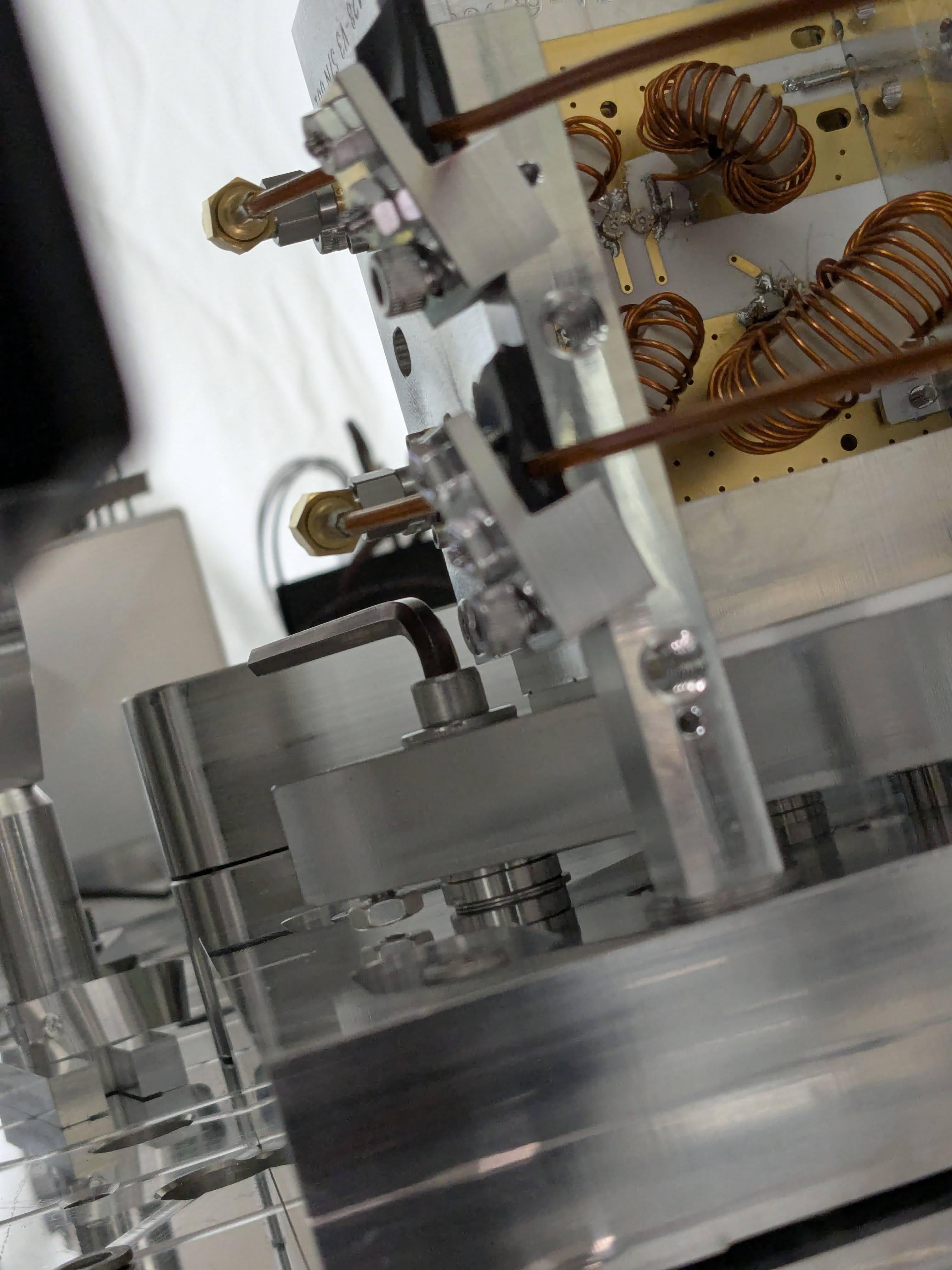
At this point we wanted to make an YAW adjustment for the EOM pivot plate. It turns out that we had to undo the hard-to-access screw I reported before (caution.jpg) and it was impossible to access when the SMA elbow was connected, a regular Allen key (or even the ball end one) interfere with the connector. It's not a huge interference but I worried that I'll damage the SMA, so we stopped it and called it the day.
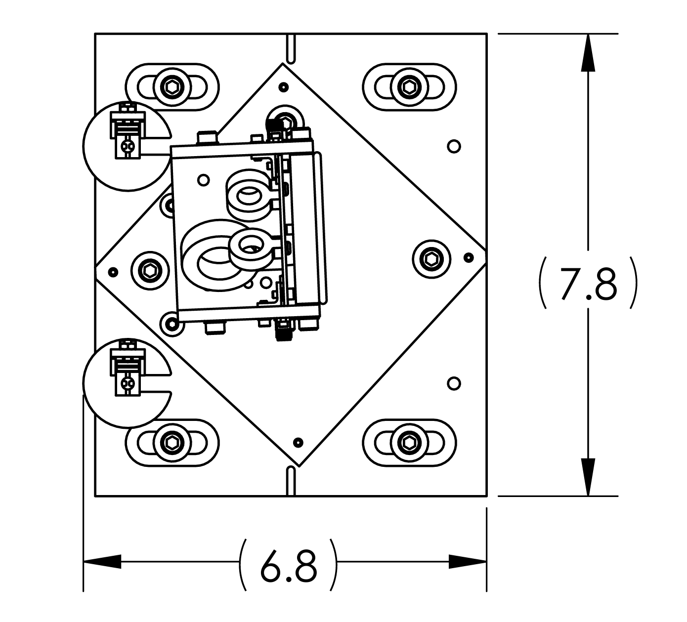
(Note for the future design: Why don't we relocate the bolt to the opposite corner (relocate_bolt.png)? )
Day 2:
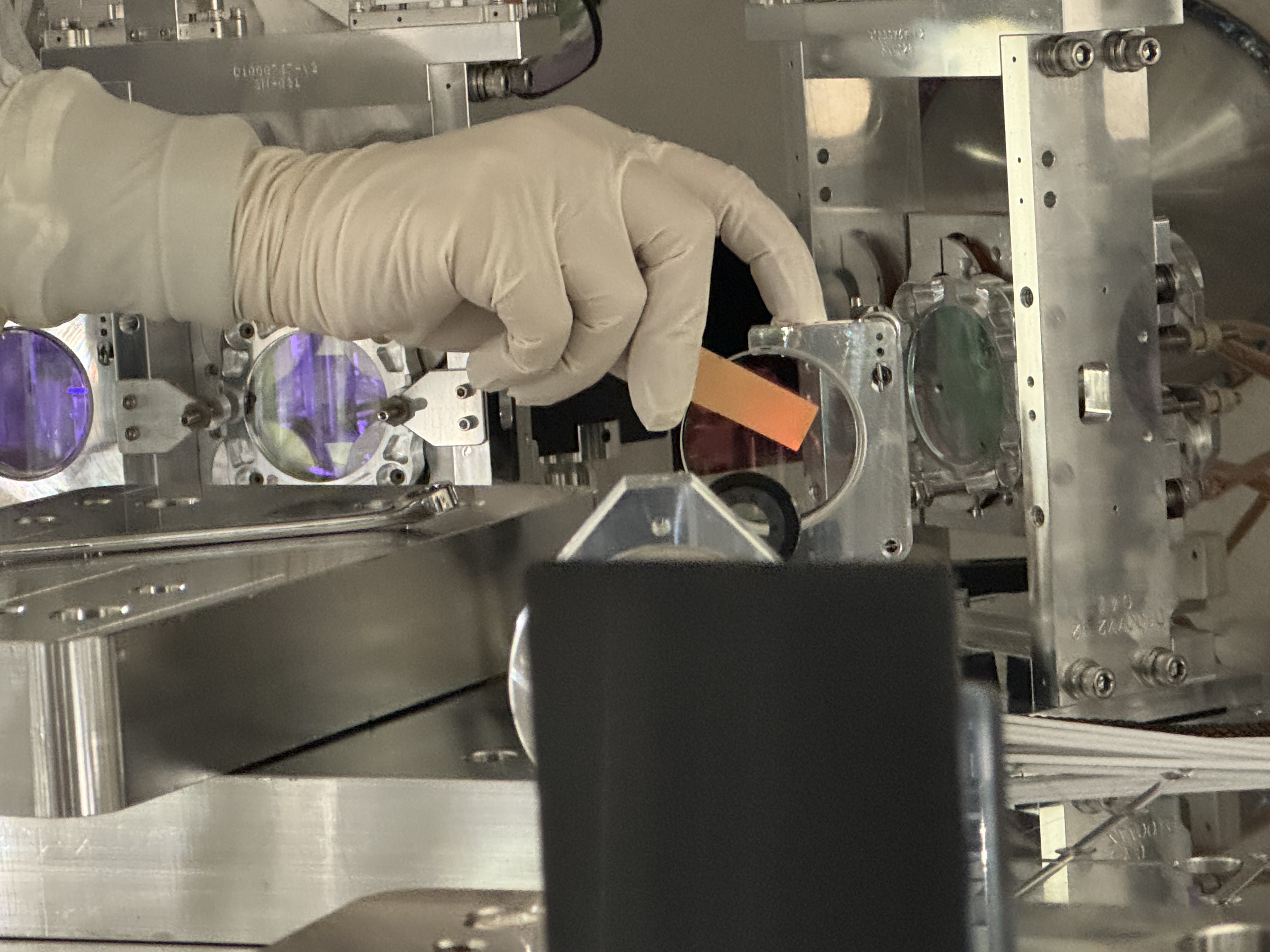
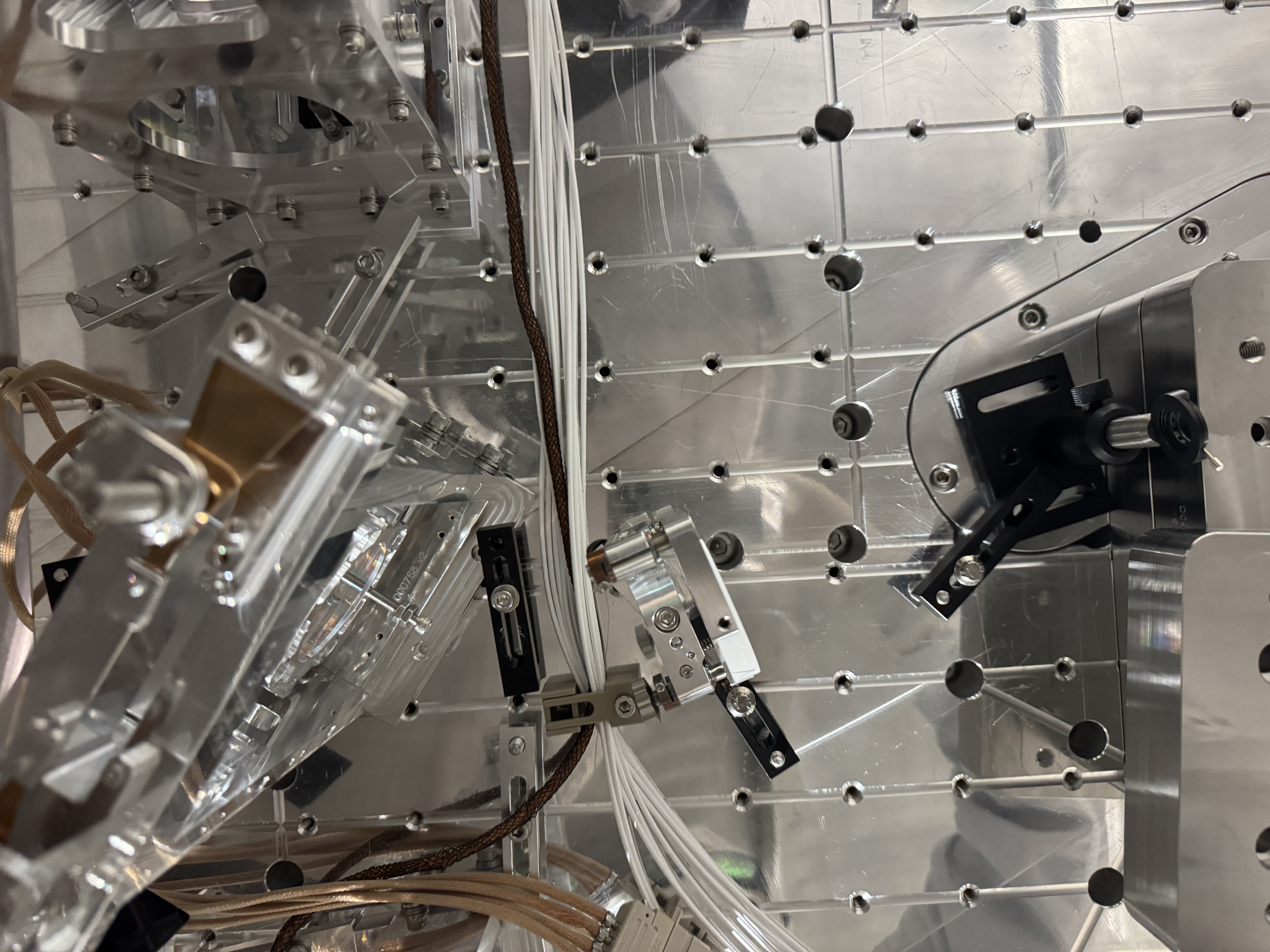
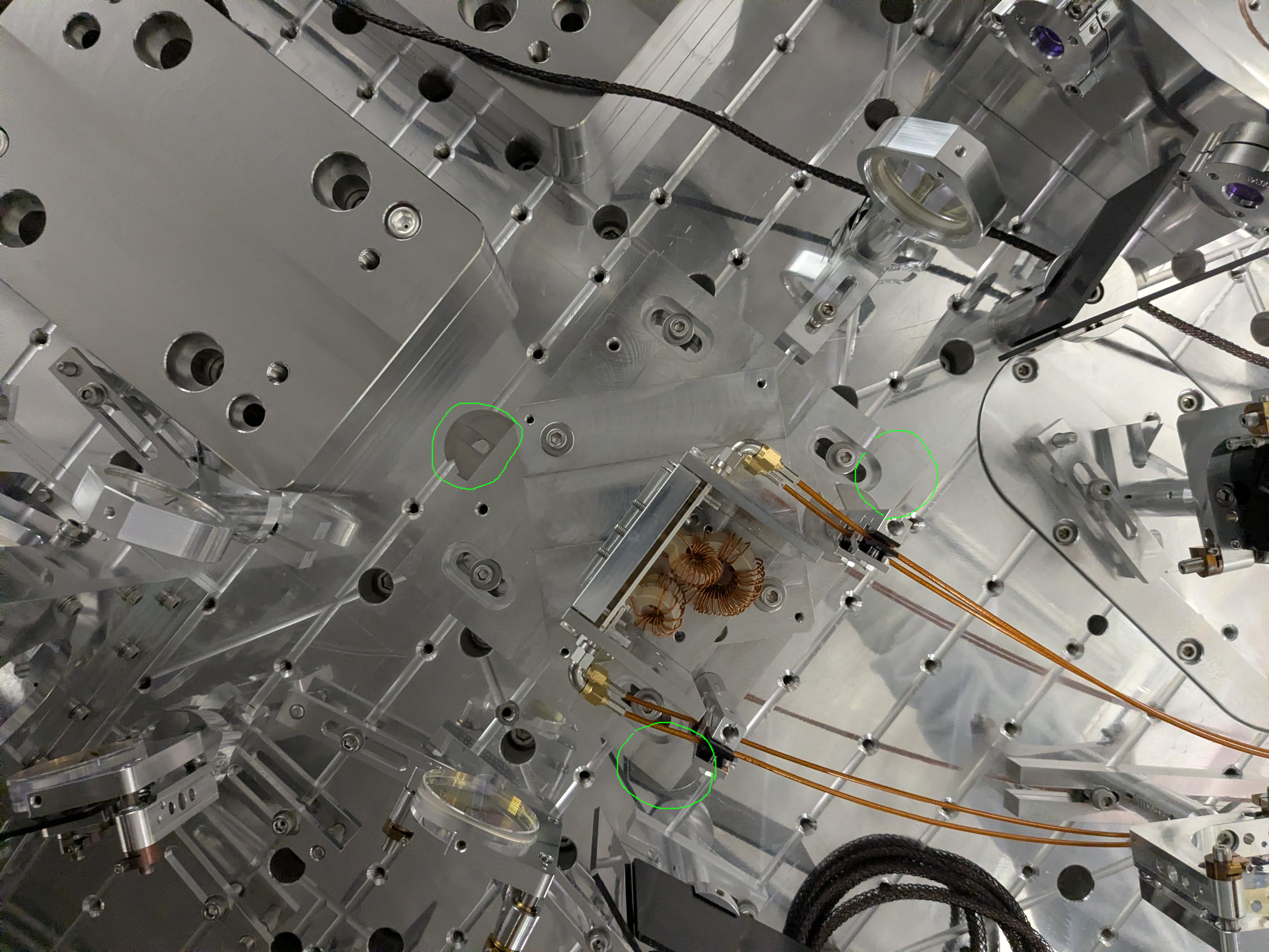
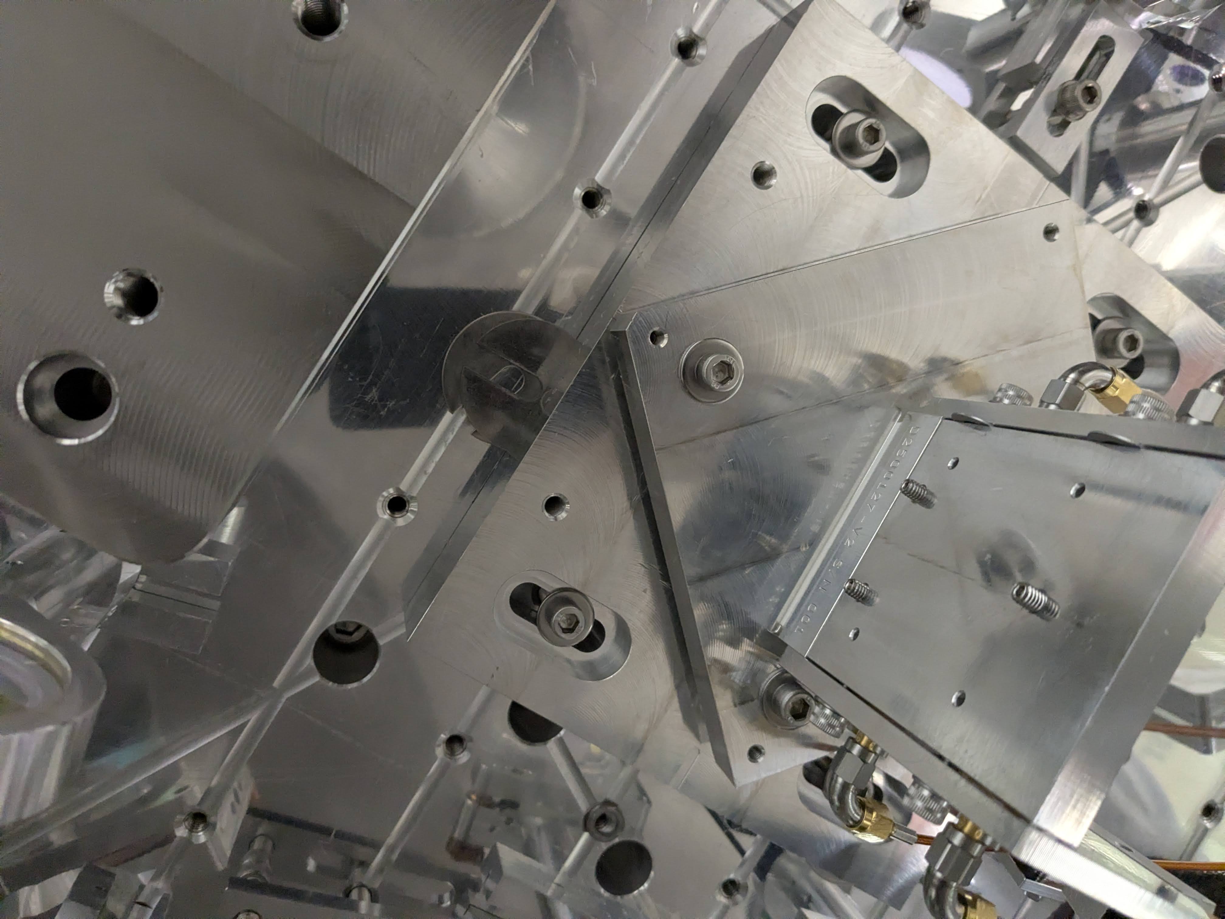
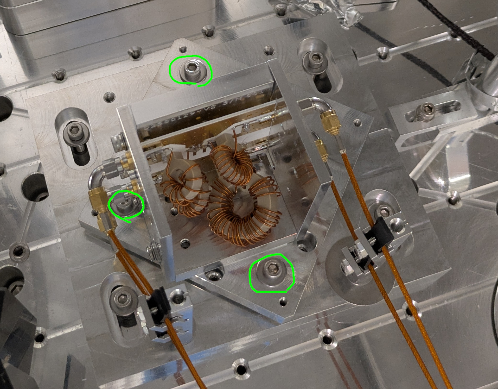
Ibrahim found us a cut Allen key that fits under the SMA (short_allen.jpg, short_allen2.jpg). We loosened three bolts circled in green in three_bolts.jpg and rotated the pivot plate. It was tedious and we needed three iterations, but we managed to reasonably center the beam position at both the input and the output of the EOM (good_in.jpg, ok_out.jpg).
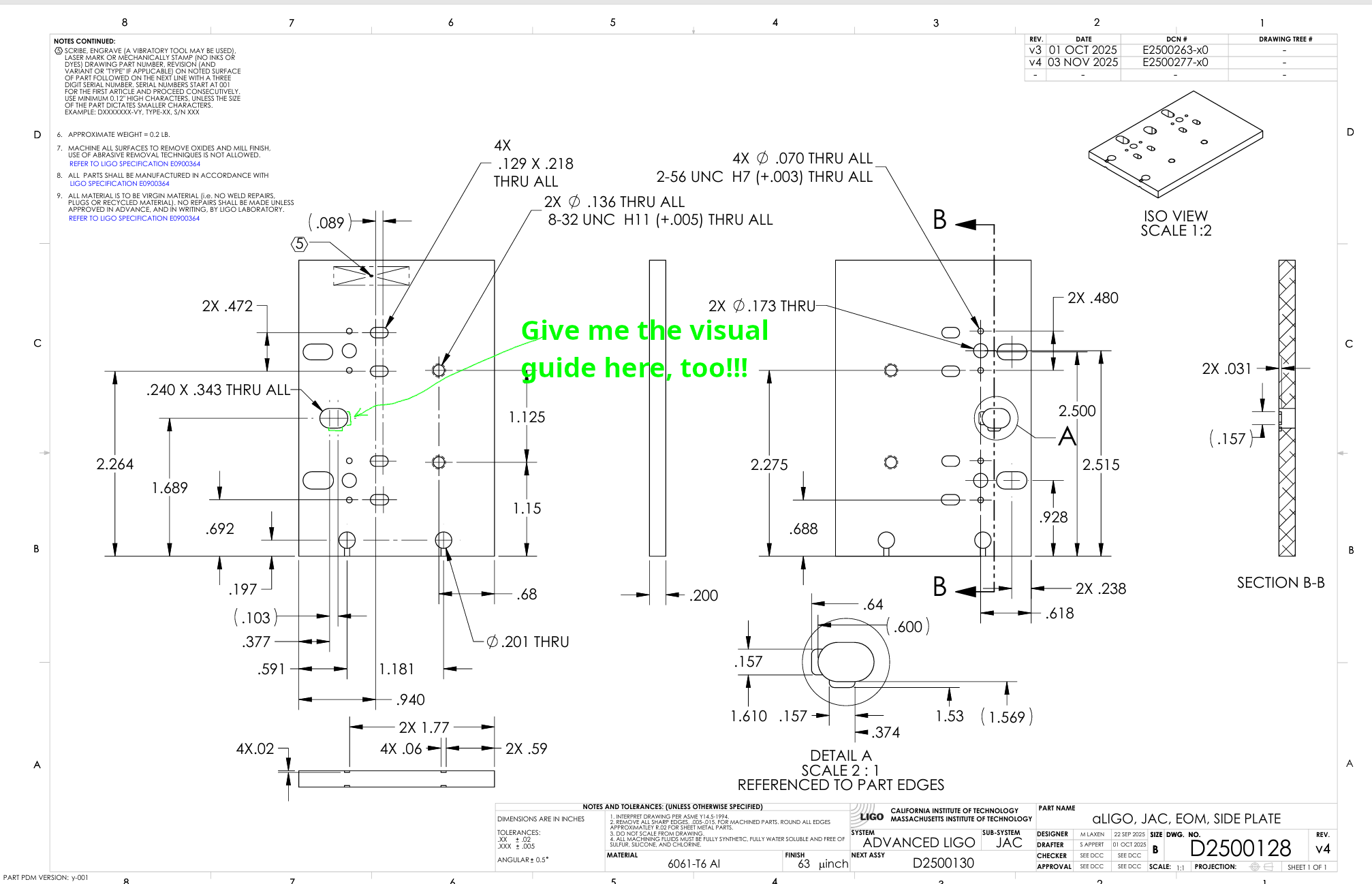
(Note for the future design: As of now there is no visual guide for the beam center position for the output side plate (the guide is on the opposite face that is not visible). This is because the input and the output side plate are the same thing (https://dcc.ligo.org/D2500128) and it only has visual guide on one face and not on the opposite face. Give me the visual guide like in visual_guide.png.)
Note: We had to loosen the strain relief such that the cables can slide inside the viton pads, otherwise the tension and stiffness of the cable act as tough springs and the pivot plate will spring back after rotation, so everything will be tedious. For each strain relief, I left one of the two tiny screws somewhat loose, and made the jam nut finger tight. The cable won't go anywhere and it still acts perfectly as a strain relief.
This was the end of the EOM alignment.
The beam shape looks better than at the end of Day 1, not sure if it's great though, it's hard to photography but something faint might be coming out of the EOM.
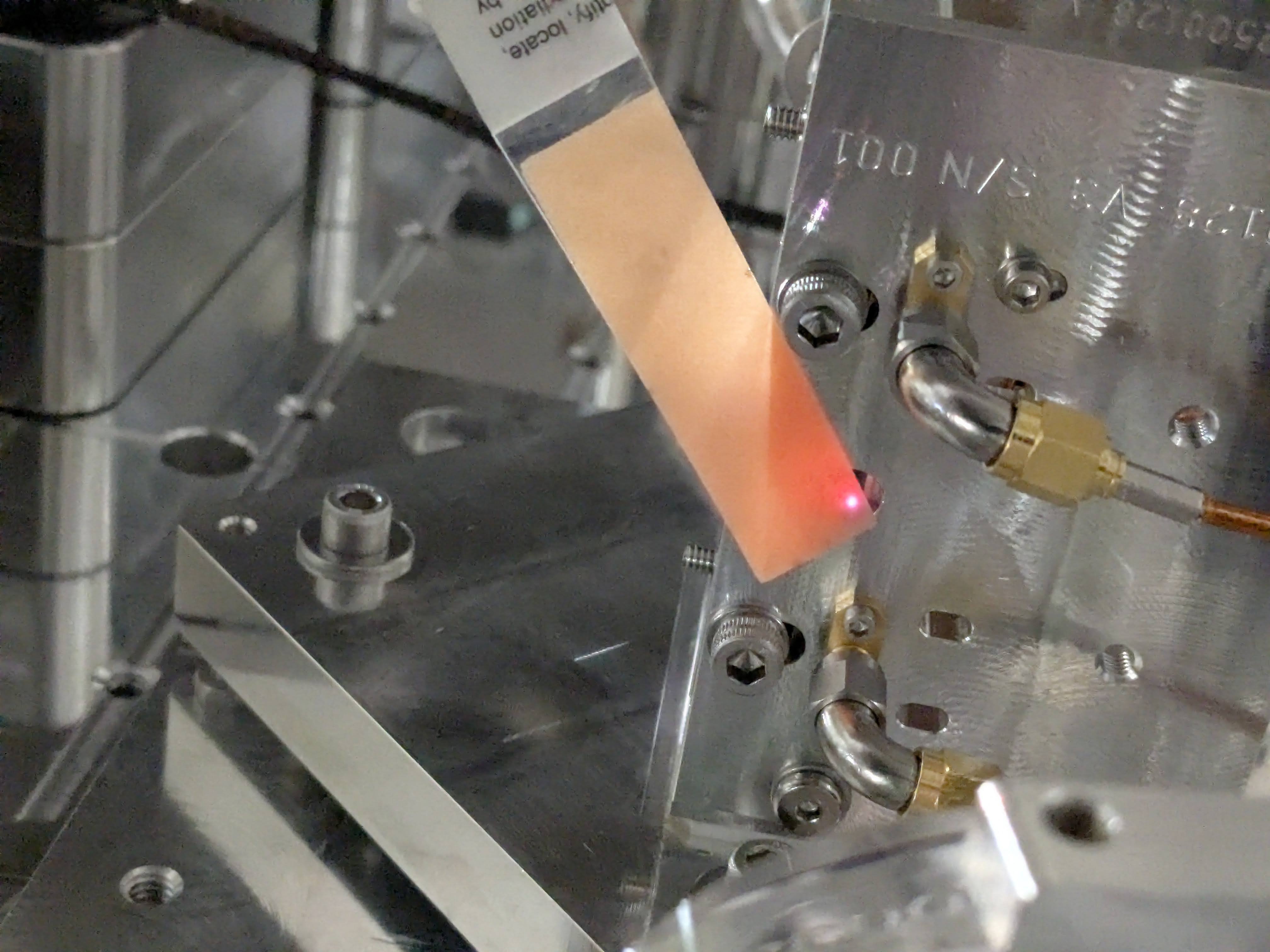
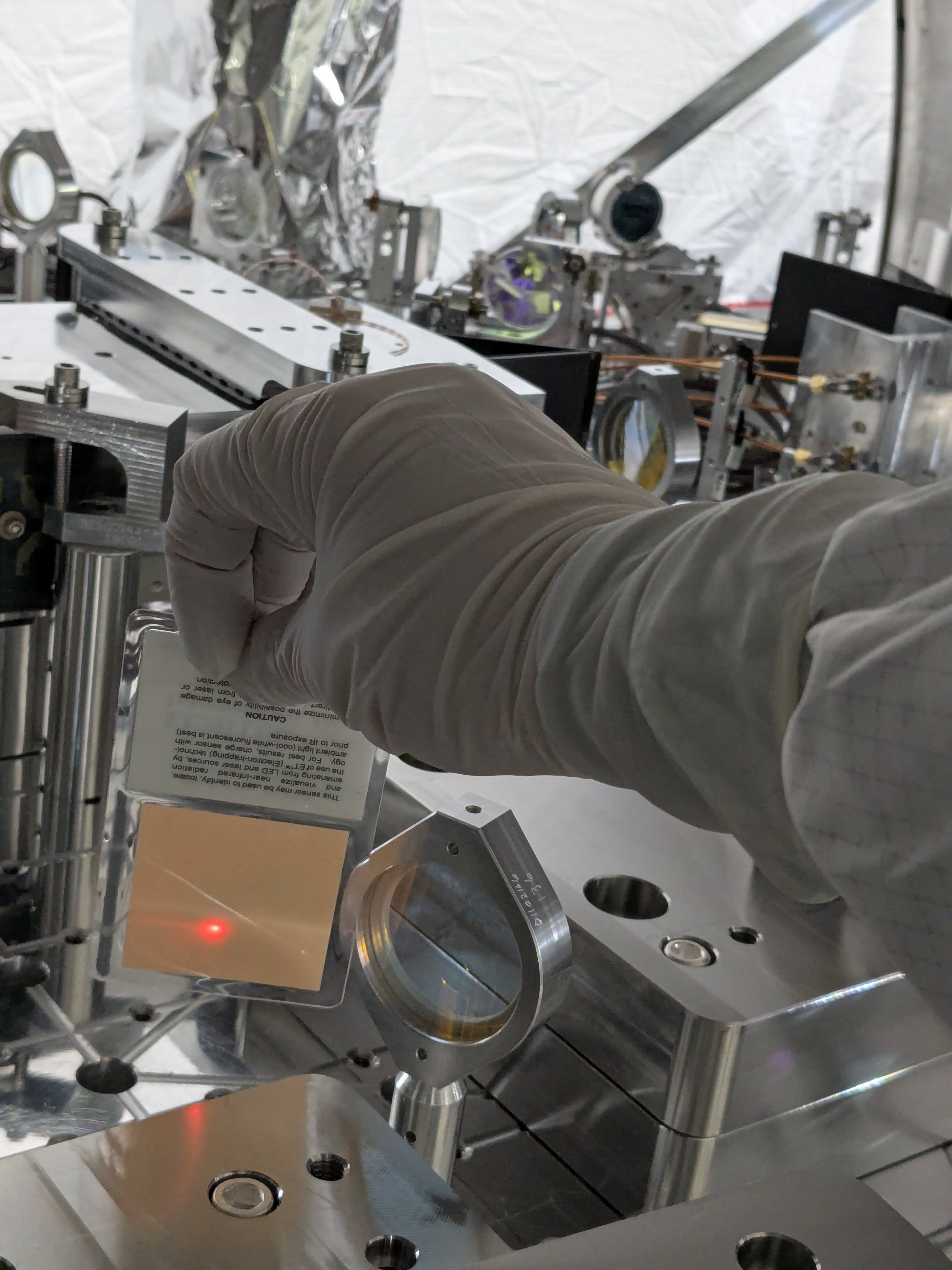
The last picture shows the ghost beam which is likely in the wrong (S) polarization.


EOM crystal serial number
Marking on the RTP container: #B1913109, 20000488M (the former is S/N)?

Tagging for EPO.