J. Freed
For the build of SPI, I measured the expected power output from a dual source Keysight 33600A through SPI's 2W amp D2500004. These measurements were taken with a E4418A EPM power meter using the HP 8484A 30dB attenuator attachment. After analyzing the data it is hard to say that the power meter power readings were accurate but the power the AOMs are receiving should be below the damage threshold of 33dBm.
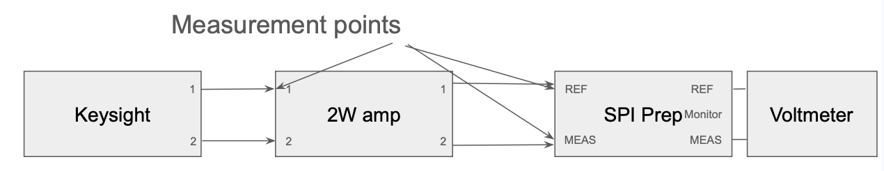
I measured the power at 2 points in the chain from Keysight -> 2W -> SPI prep, for both channels. (SPI_Build_RF_Diagram.png) The first point is just before the 2W amp, and the second point is just before the SPI prep for both channels. Then I compared that with what the output monitor voltage was showing on SPI prep for both channels.
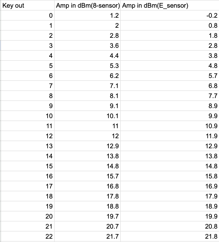
Power_Before_2W_Amp.png Is the data collected from power measurements just before the 2W amplifier. The limit of 22dBm is the limit of the keysight. From this it can be seen that there is not a 1-1 measurement between what the keysight says it is outputting and what the HP 8484A sensor is measuring. This difference is also changing based on the input power itself. With lower power overestimating what the keysight says its outputting, and higher power underestimating what the keysight says its outputting. This is a problem with the probe as switching out the probe to an E-series gives a relatively consistent error of -0.2dB between what the keysight says its outputting and what is being measured. Unfortunately the HP 8484A sensor is the only probe that can measure up to the 32-32.5dBm needed for SPI. Interpolating the results of the HP 8484A sensor up to 32 dBm gives approximately a 0.4dB underestimation of the power.
Then I took a measurement of the power after the 2W amp at the end of the cable that would plug into SPI prep. Namely I adjusted the power from Keysight, such that the output measured on the probe was 32dBm which is what SPI prep is expecting accounting for any possible underestimation of the power. Note that power past the 2W amp decreases over time (by about 0.5dB total) as the device warms up so I had to wait a couple of hours after start-up to take this measurement. The results were:
AMP 1 (Which goes into the ref path) measured 32dBm when the keysight displayed: -1.7dBm
AMP 2 (Which goes into the Meas path) measured 32dBm when the keysight displayed: -0.3dBm
Be aware that that 32dBm has an error of +/- 0.5dB due to the factors listed above.
Then using the fact above, I found that the whole AMP 1 chain has a gain of 33.7 dBm from what the keysight displays. And AMP 2 chain has a total gain of 32.3dBm from what the keysight displays. Using this fact I could find the voltage associated with each of the monitor channels of SPI prep.
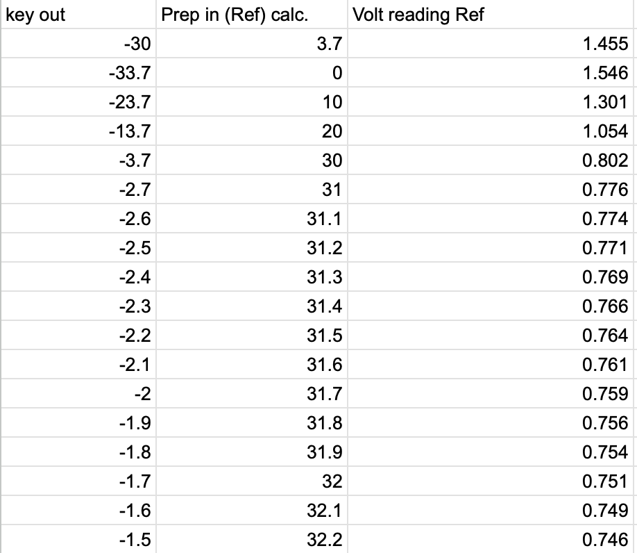
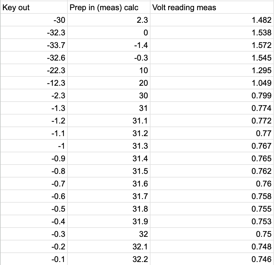
Monitor_read_AMP1_REF.png and Monitor_read_AMP2_MEAS.png show the monitor reading voltage vs the approximate input RF power into SPI prep. for both channels. Interpolating the results gives a calibration equation between RF power and monitor voltage of:
AMP 1 (REF): [V] = -0.0249*[dBm] + 1.5480
AMP 2 (MEAS): [V] = -0.0246*[dBm] + 1.5387
With both channels reaching 32dBm around 0.75V on the monitor channel this gives an easy target for controling the power.


J. Kissel
Easy look up table after setting up Keysight 33600A per T2600039, and setting the amplitudes as we have had for most of the build ::

CH1 = AMP 1 = REF = M2 MON
    f = 79.995904 MHz (79,995,904 Hz)
    amp = -1.7 dBm
    M2 MON = 740 mV

CH2 = AMP 2 = MEAS = M3 MON
    f = 80.000000 MHz (80,000,000 Hz)
    amp = -1.4 dBm
    M3 MON = 755 mV

Remember to turn the output ON for each channel.