J. Freed
Update from last time 90273:
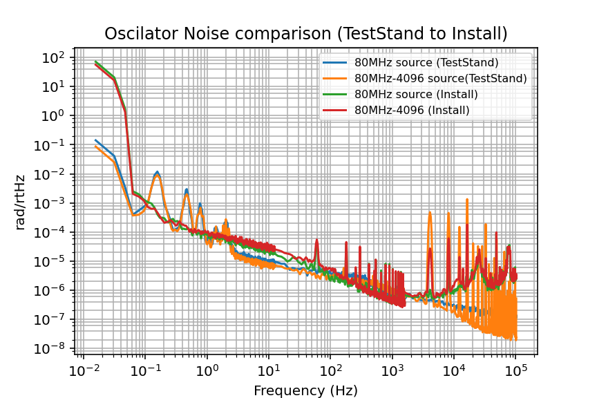
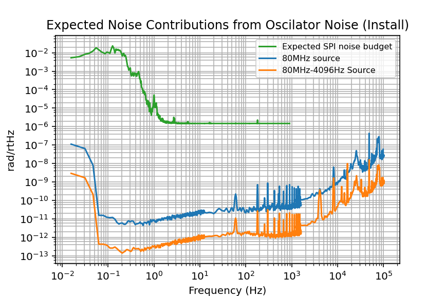
I took phase noise (PN) measurements of the SPI RF chain yesterday and found that nothing drastically changed in performance from test stand set up to final set up DM_Install.png. And that Oscillator noise is not a noise limit for SPI DM_Install2.png (The shape changed is calculated by the same equation as 88457) Note that PN measurments can be limited by the reference frequency. As such, the plots of PN are plotting a maximum noise. The actual noise could be even less (see notes).
The main thing a phase noise set up needs is a reference signal with the same frequency as the RF signal being tested with good performance. An OCXO that is timing locked to LIGOs 1pps timing signal or a frequency generator that is locked to a 10MHz signal produced by that OCXO is required. Where to get this specific requirement in the LVEA? J. Kissel gave the idea to use the Frequency generator that produces the TCS 40.68MHz signal to be delivered to the TCS-R2 rack about 12ft away from SUS-R2.
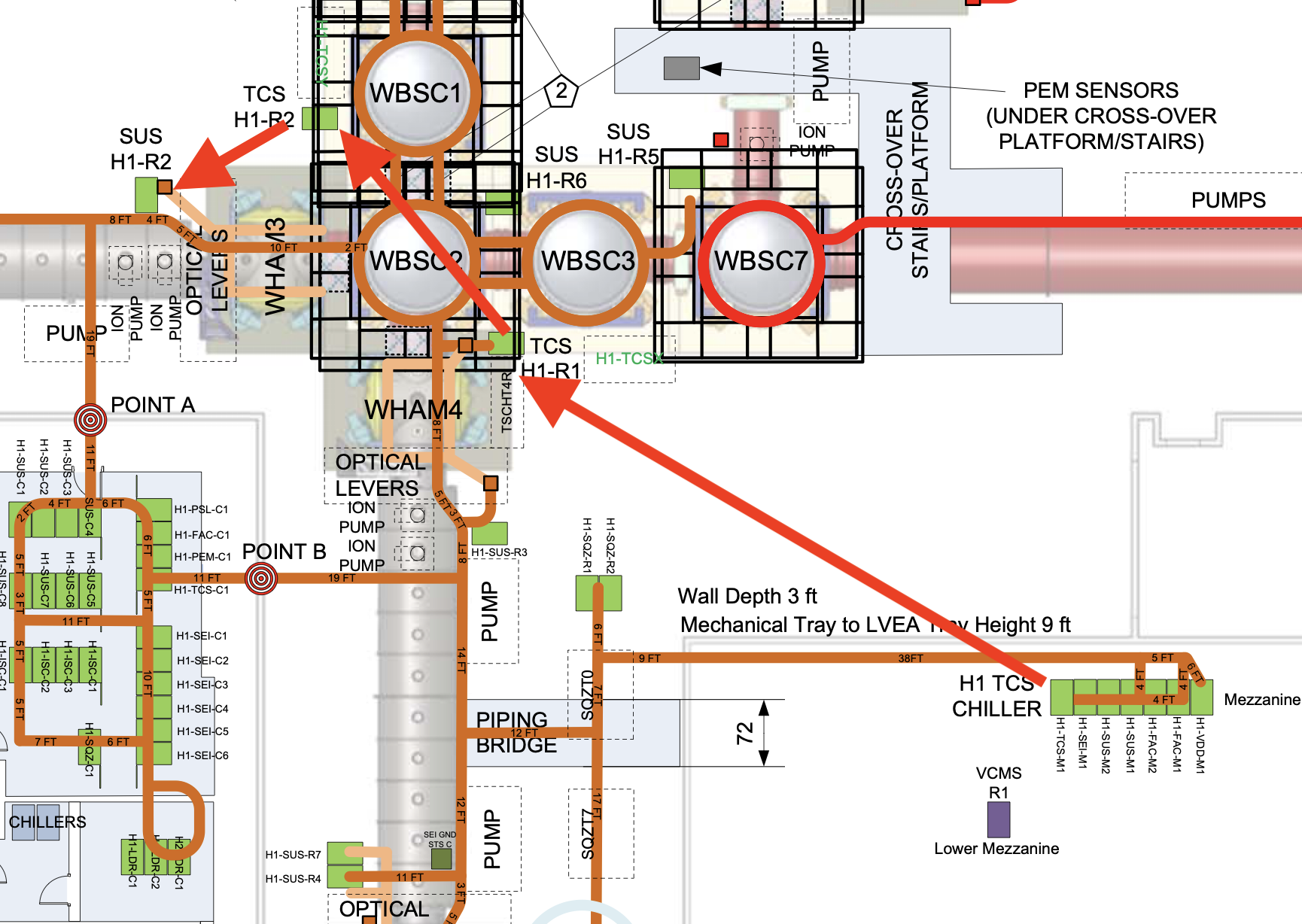
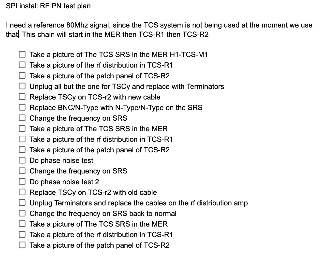
SPI_PN_layout.png Shows the layout of this set up. A 40.68MHz signal is produced in the MER TCS-M1 rack by a SRS SG382 function generator Screenshot2026-05-27at103451 AM.png. Where it is sent to the LVEA rack TCS-R1. The signal then is sent into an RF distributor Screenshot2026-05-27at103458 AM.png where it is split into signals for TCSx, TCSy, and a mon channel. TCSy is then sent to TCS-R2 Screenshot2026-05-27at103806 AM.png. I could then run a long cable to SUS-R2 from TCS-R2 Screenshot2026-05-27at103523 AM.png and by adjusting the frequency of the frequency generator so I could perform the PN test. Before switching the frequency on the SRS, I made sure to replace the wires in TCS-R1 going to TCSx and the mon channel with terminators and replace the wire going to TCSy in TCS-R2 with my own long cable. I then did the reverse order to put TCS back. (SPI_Install_PN_TestPlan.png is the plan I followed.)


Notes:
The TCS SRS SG382 function generator N-Type Connector is burnt out. I cannot find a report on this but will add a comment if that changes
The SRS SG382 function generator has 2 ports, a BNC and a N-type. The BNC typically handles lower power and lower frequency while the N-type handles higher power and higher frequency. The 40.68MHz nominal signal can go through either port while the 80MHz I need for the PN test must go through the N-Type port. This means the PN measurements I took went through the burnt out N-type.
I confirmed this by checking the power of the signal at sus R2, then by only changing the port, checked the power again. With the nominal 40.68MHz signal outputted at 13dBm from the TCS function generator BNC Port. I measured 11.2dBm at SUS-R2. By only swiching to the N-type port, I measured -18dBm. A ~30dBm drop. Technically I also switched out a cable from BNC/N-Type to N-type/N-type so I checked that too by using another N-Type/N-type and there was no change in power between cables.
This did not seem to have a drastic effect on the PN measurements except for a slightly higher general noise floor and alot of noise at high frequency which SPI is insensitive to. This has no effect on the conclusion that Oscillator noise is not a noise limit for SPI.