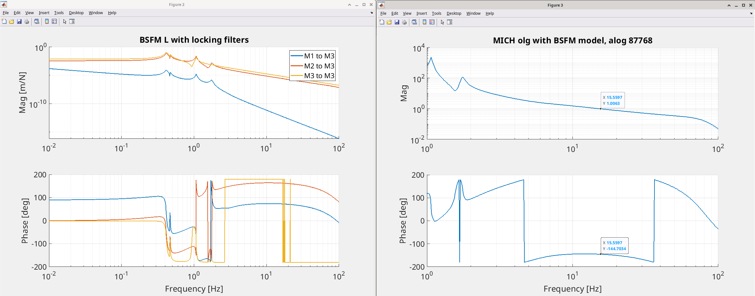
Inventory of DRMI locking data in 87768. By eye (someone overwrote the data in the MICH xml since it was taken), the MICH UGF is roughly 15 Hz when we achieve DRMI 1f lock.
I used the BSFM model in /ligo/svncommon/SusSVN/sus/trunk/Common/MatlabTools/TripleModel_Production (bsfmopt_metal) to generate a model of the MICH loop using the MICH control filters and BSFM locking filters. I applied a fudge factor to generate a loop with a 15 Hz UGF, which I then used to estimate the m/ct calibration required to generate a BBSS model, assuming we have the same optical gain when locking with the new beamsplitter. (suspension calibration table is G1100968). This model indicates that the MICH L M1/M2 crossover is 30 mHz, which agrees with the data in the table in Evan Hall's thesis, Table 2.4 page 33. See first attachment for BSFM model
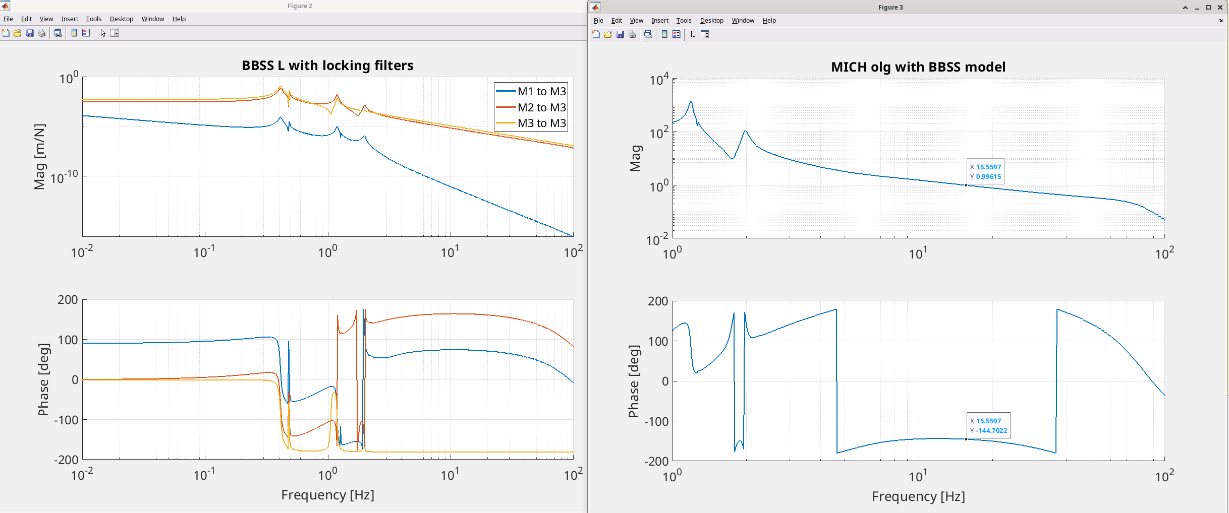
Then, I generated a BBSS model in the same triple model directory using bbssopt. I applied the same beamsplitter locking filters and MICH control.
Overall, it shows us that if we use the same feedback design with M1/M2 control, we should end up with a MICH loop that is almost the same as the one we have now in DRMI 1f lock- 15 Hz UGF, 30 mHz crossover between M1 and M2. See second attachment for BBSS model
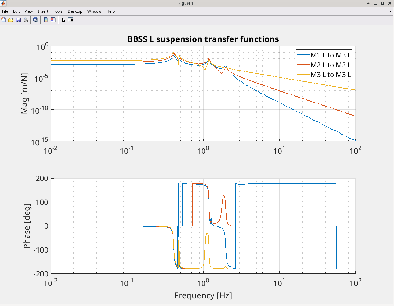
It also seems to me that it should be fairly straightforward to move the MICH length control from M2 to M3, although we will likely need to adjust the locking filters to achieve the same crossover frequency. See third attachment of the comparison of each stage sus transfer function to M3.
I have not been able to generate a model of the oplev damping that looks reasonable, so I will poke around the alog to see if I can figure out what the design is supposed to be.
Executive summary: we should have no problem locking DRMI with the current MICH and BS control scheme, and it shouldn't take that much effort to move BS feedback from M2 to M3 if we so choose.
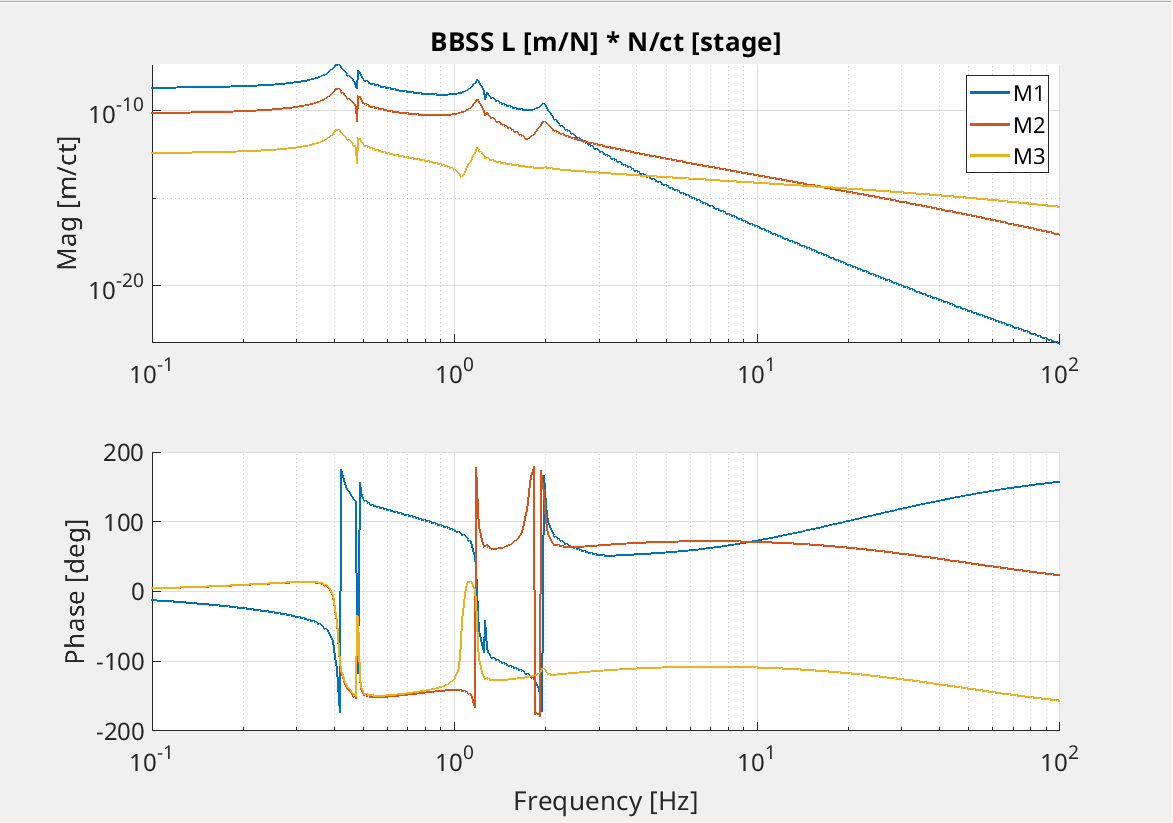
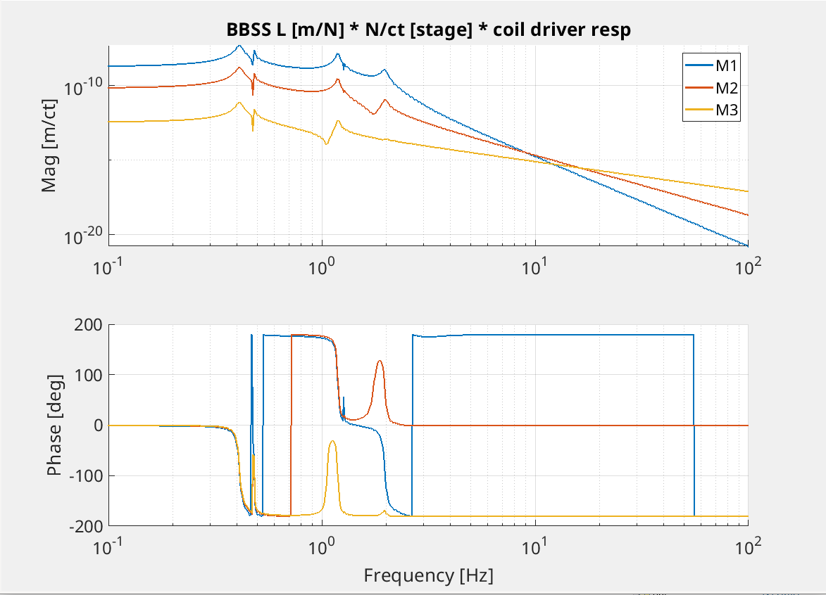
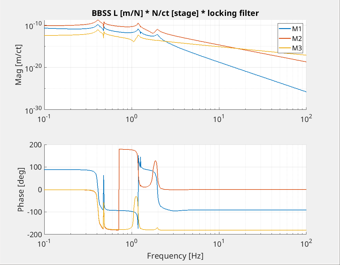
Here are a few additional plots that also describe the actuation authority of the BBSS in length. Thanks to Jeff for encouraging me to make these plots!
The first plot shows the resulting displacement in m you get from each BBSS stage drive request in counts. This drive request assumes you have properly compensated for the coil driver frequency response. This plot shows that below 3 Hz, the top stage is the strongest actuator, whereas M2 is best for the region between 3-15 Hz, and we will get the best response from M3 above 15 Hz.
Next, I made a variation of the plot without compensating for the coil driver response. I still don't fully appreciate the significance of this plot, but I will quote Jeff calling this the "maximum possible range plot" in a given coil driver state.
Finally, I applied our digital offloading filters. Right now, because we always drove the BSFM from M2, the M2 locking bank includes a filter that is essentially an inversion of the M2 to M3 response. I decided to neglect the inclusion of that filter here. I also don't have any of the usual notching that's present, since we still have to determine the appropriate notches for the BBSS. All that really leaves is the top stage integrator and gain factor, which currently sets the M1/M2 crossover frequency to 30 mHz.