J. Kissel, J. Warner
WP:13657

As we starting working through comparisons of SPIH23 with the first instantiation of real-time differential signals computed in the seiproc model with on-board ISIHAM2 and ISIHAM3 sensors, we realized that
    (a) We should remove a layer of confusion and use the sensor-corrected, "inertial" CPS, rather than the un-corrected CPS. Otherwise, the local "input to the blends" and thus the local super sensor will disagree with the seiproc re-construction as shown in LHO:91990 and LHO:92026; and
    (b) We're getting greedy in trying to re-create a super-sensor that combines the local GS13s and CPS with a re-production of the blend filters, and then subtracts -- all so we "just" have one trace to compare to SPI signals. However, to reduce computational complexity and signal calibration confusion, we should create a back-up "good enough" solution and do what we did during the SPI conceptual design phase (see LHO:83412).

So, yesterday, with the help of Dave (LHO:92104), we installed two changes to the seiproc calculation of (HAM3) - (HAM2) = "H23" and (HAM4) - (HAM5) = "H45" signals.
    (1) The change that "fixes" (a), we mapped the sensor corrected CPSs from the ISIHAM2, ISIHAM3, ISIHAM4, and ISIHAM5 models to seiproc, rather than the "raw" CPS.
    (2) We built up parallel infrastructure to the blended super sensor reconstruction that "just" subtracts (HAM{3,4} - HAM{2,5}) GS13s and (HAM{3,4} - HAM{2,5}) GS13s, and (HAM{3,4} - HAM{2,5}) CPS and (HAM{3,4} - HAM{2,5}) CPS. No blends, no calibration, just straight subtraction.

The output of the matrix that does the subtraction (2) is fed into filter banks, where -- for now -- only the Y and Z degrees of freedom have an optional "to_nrad" (from [nm]) filter that divides the differential signal by 15.4 [m], i.e. a gain of 0.064935 [1/m].

The MEDM GUI is still under construction, but I've got enough of it functioning that you can see the system:
    . Screenshot 1
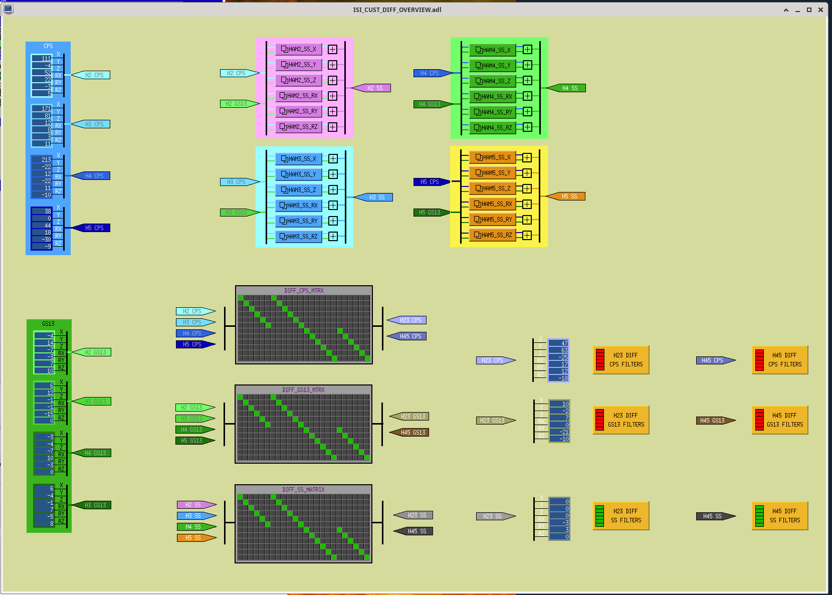
        The beginnings of the ISI DIFF overview screen. This is linked from the SITEMAP via the pink SPI menu.
        On the left is all of the input signals (the seiproc version) from each of the HAMs' CPS (in shades of BLUE) and GS13s (in shades of GREEN).
        Again, now the incoming CPS are the sensor-corrected CPS.
        At the top middle is the infrastructure that was already in place to blend the CPS and GS13s together.
        At the bottom middle, there was only one matrix to subtract the reconstructed super sensor, but now there're two more matrices to subtract the CPSs and GS13s independently, respectively.
        Finally, again where there was only one set of filters to filter the reconstructed super sensor, now there's two more sets of filter banks to independently calibrate or at least unit convert the differential CPSs and differential GS13s.

    . Screenshot 2
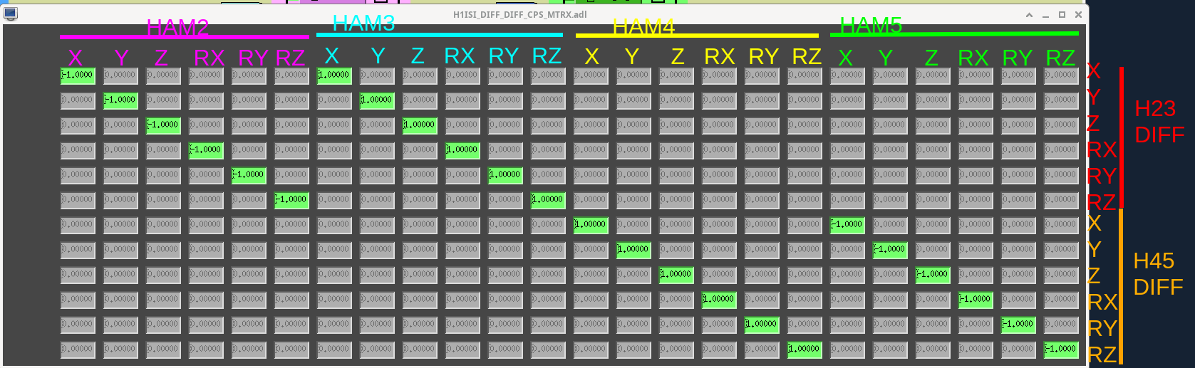
        A shot of the differential CPS matrix, with visual aides drawn on for now (I'll add these labels to the screens themselves in due time).

    . Screenshot 3
        A shot of the differential CPS output filter banks, with the "to_nrad" filter shown turned ON in the Y and Z banks.

    . Screenshot 4
        A shot of the blend filters for the X DOF of HAM2, just to give folks the impression of what's going on here.
        All of these filters haven't changed since Jim validated that he copied the over from the local ISI models with good fidelity (see LHO:92054).

I've turned ON the infrastructure as shown, and accepted those values as "ON" into the SDF system.

So -- if you're looking to use these channels, here they are explicitly:
    (I) Differential CPS (in [nm] or [nrad]):
        H1:ISI-DIFF_H23_DIFF_CPS_{X,Y,Z,RX,RY,RZ}_OUT_DQ

        NOTE: This is different and separate from the existing "CPS DIFF" channels, e.g. ISI-DIFF_HAM2_CPS_X -- as these channels are each chamber subracted from *the ISI BS* CPS. Hence the unfortunate new channel "feature" of having DIFF twice in the channel name.


    (II) Differential GS13 (in inertial sensor units, asymptotes to 1 [nm/s] or 1 [nrad/s]):
        H1:ISI-DIFF_H23_DIFF_GS13_{X,Y,Z,RX,RY,RZ}_OUT_DQ

    (III) Pre-subraction, blended, re-constructed super sensor for each chamber (test points, not filter banks; in [nm] or [nrad]):
        H1:ISI-DIFF_{H2,H3}_BLND_SS_{X,Y,Z,RX,RY,RZ}_DQ

    (IV) Differential Super Sensor (in [nm] or [nrad]):
        H1:ISI-DIFF_H23_SS_{X,Y,Z,RX,RY,RZ}_OUT_DQ

Again -- for the time being -- the Y and Z channels are calibrated into [nrad] of (differential Y) / L and (differential Z) / L so they can be directly compared with SPI optical lever YAW and PIT signals, respectively, directly.

May it all make sense now! #crossesfingers


Please, Use the CPS and GS-13 Sensor Differences to Watch the HAM2-3 relative motion, Not the Supersensor Differences
To the extent that the table motion is limited by the noise of the supersensor (and it often is, recall that ground motion though the CPS is equivalent to 'sensor noise', even though we usually track it separately from the CPS readout noise), you can not see that motion in the supersensor. In the past, we've always looked at the CPS or GS-13 signals to estimate the real table motion, and we need to keep doing that.
Questions? I've written this up in T2500279-v2 "Sensor noise coupling to Sensor Output", look at section 7.
One suggestion is to take the sensor difference, filter it, and show that. Do this for both sensors. Do NOT use complementary filters (why would you?). For example, calculate (HAM3 corrected CPS - HAM2 corrected CPS) and filter it with an agressive low-pass filter to keep the part of the spectrum of interest, probably below about 0.5 Hz. For the GS-13 you should probably high pass the difference around 0.1 Hz.