Eric, Ryan S, Camilla, Sheila
All week we have been working on getting a set of OMC scans and beam profile measurements for different psams. We have both sets of data now, with plots and scripts coming soon next week.
OMC scans
We started with a script that Begum gave us from HAM6 work at LLO. We set up ASC loops to go from ASA and AS B DC signals to ZM4 and ZM5 (as described in 90742). We struggled a while to lock the OMC on the seed beam in air, hampered by 90754. With that noisy OMC lock, yesterday Camilla manually aligned OM3 and the OMC suspension carefully to maximize the 00 transmission. We then added offsets to H1:OMC-ASC_QPD_{A,B}_{PIT,YAW}_OFFSET, which is not the usual location for OMC QPD offsets. We will need to get rid of these offsets before we go back to locking.
OMC A offset: PIT 0.088 YAW: 0.133 OMCB offset: PIT 0.27 YAW: -0.22
We found that we were able to move the psams, whih misaligns the OMC terribly, run the centering loops to the ZMs, then run the OMC QPD loops to bring the 1st order peaks back down to a couple % of the 00 peak repeatedly. We spent some time modifying and then debugging the script that Begum shared with us.
It takes in a list of ZM4 and ZM5 strain gauge values, moves the psams servos target to that point and waits 30 seconds with the ZM centering loops on (it doesn't check the acutal value of the strain gauge, perhaps this would be a good thing to add next time). It then turns on the OMC QPD loops for 20 seconds. It then takes a 100 second ramp of the OMC PZT, and saves the times and ZM strain gauge targets into a yaml file.
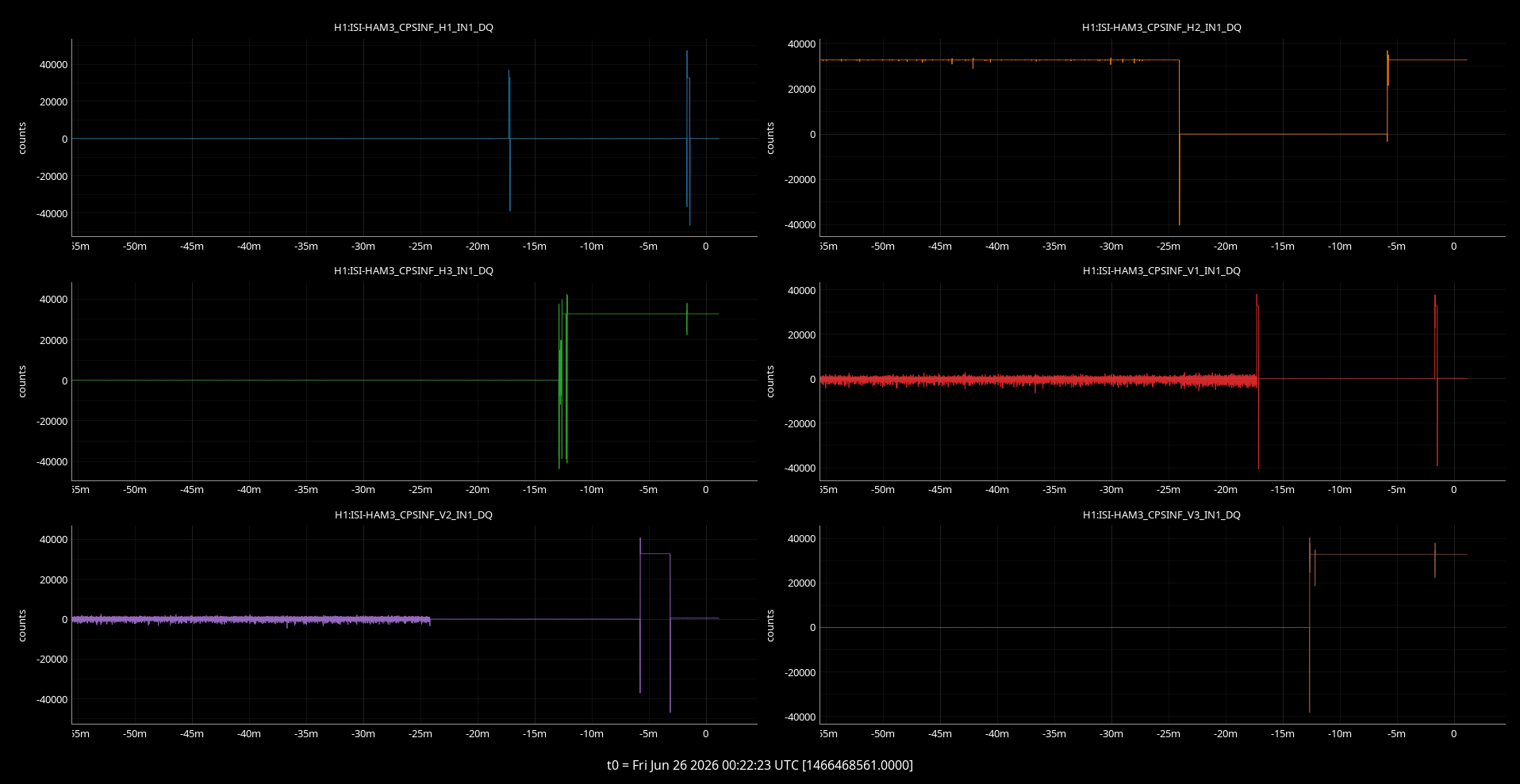
There is a template you can use to watch all this at userapps/sqz/h1/Templates/ndscope/OMC_psams_scans_monitor.yml The script that runs these sweeps is at sqzutils, or /ligo/gitcommon/squeezing/sqzutils/omc_scans_sweep_psams.py There is also a script there that loads the data, identifies the peaks and estimates mode mismatch and misalignment there, analyze_psam_omc_sweeps.py. A preliminary plot is attached (apologies for the color choices and linear y scale here).
M2 profile measurements
Eric and Ryan S took a series of M2 profiler measurements of the beam on SQZT 7 today, doing the alignment procedure at each strain gauage setting (they didn't adjust ZM alignments). Their data is in here, we will post some plots of this next week.
Note about ZM5 strain guage
While Eric and Ryan were making beam profile measurements, they ran into a situation where ZM5 would not go the strain guage setting of 2. I was able to get it to go to 2 manually, but noticed that there were times when the strain gauge voltage dropped to zero, similar to a problem seen at LLO HAM6 recently. We should follow up on this next week.


