[Tom, Ibrahim, Oli]
Summary: The yaw / pitch coupling seen on the BBSS is not due to the the coil driver chain.
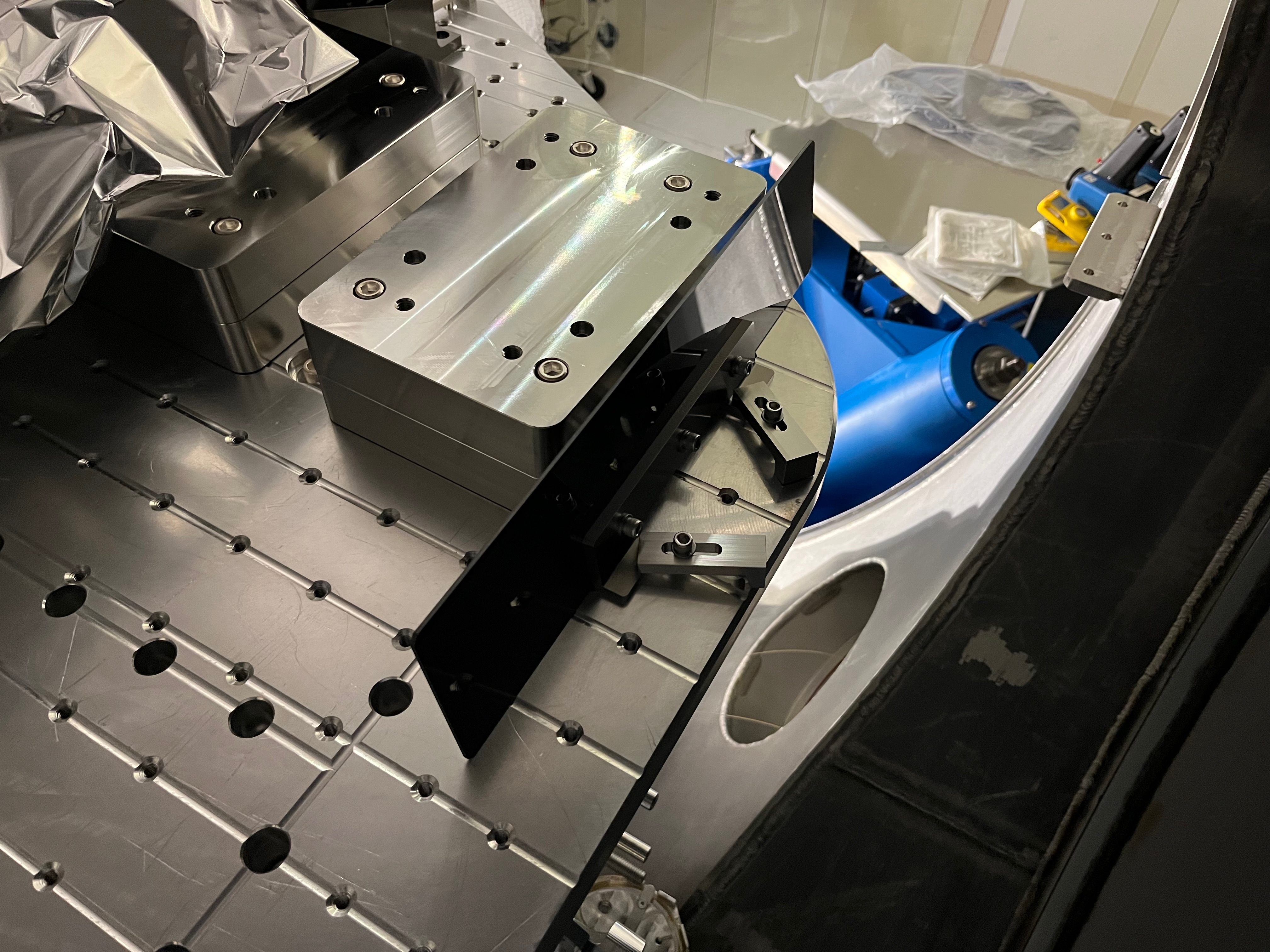
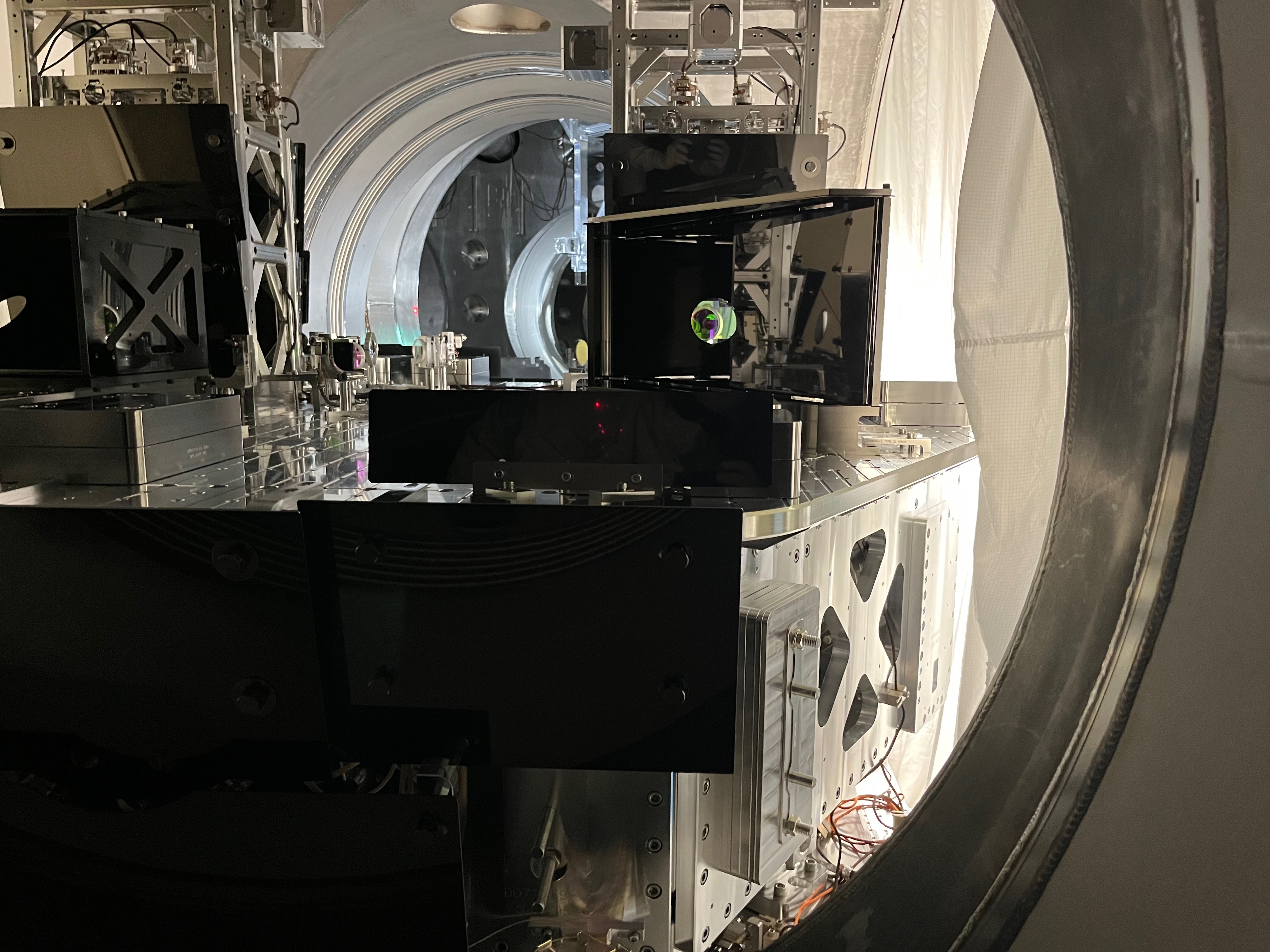
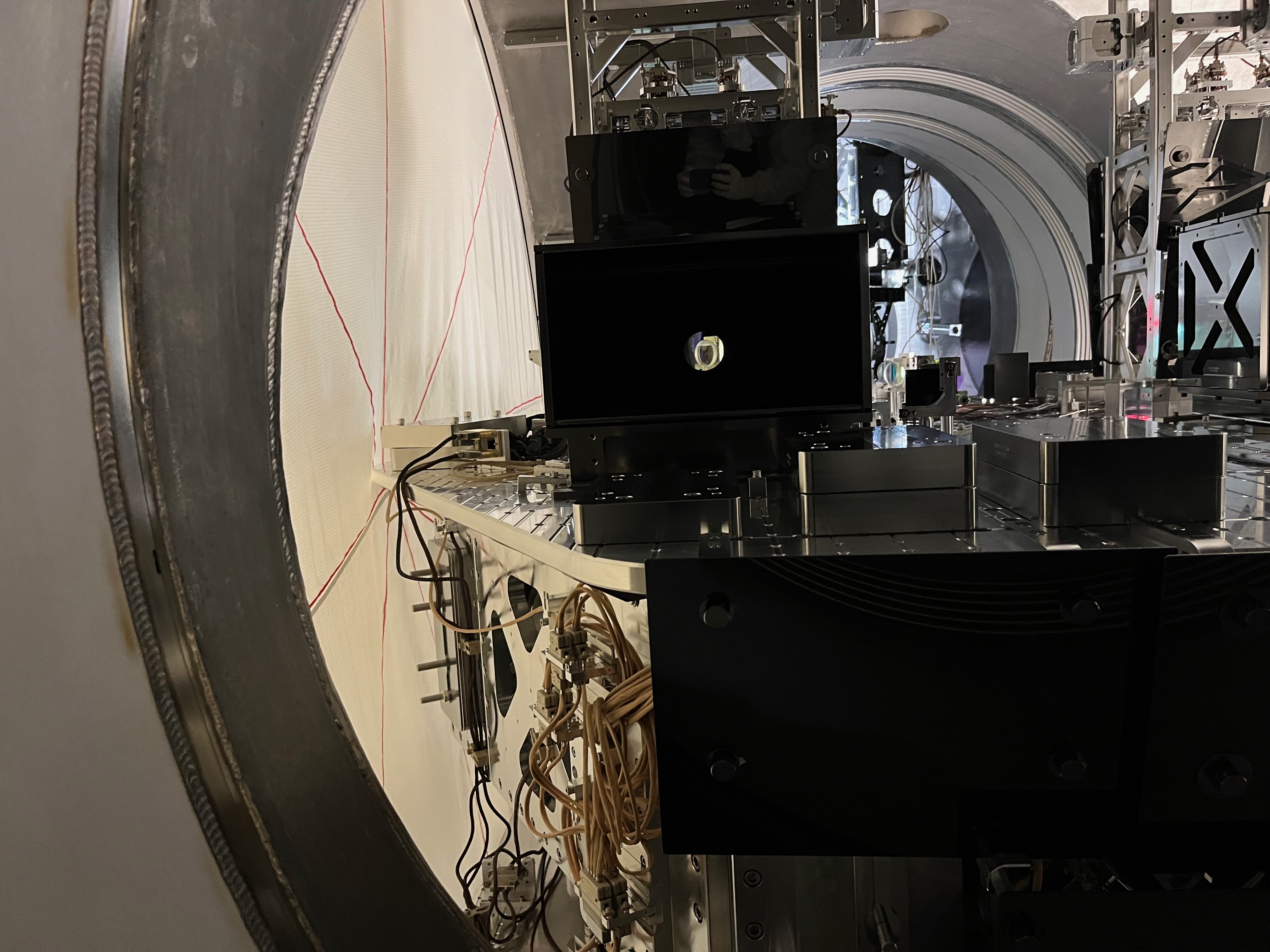
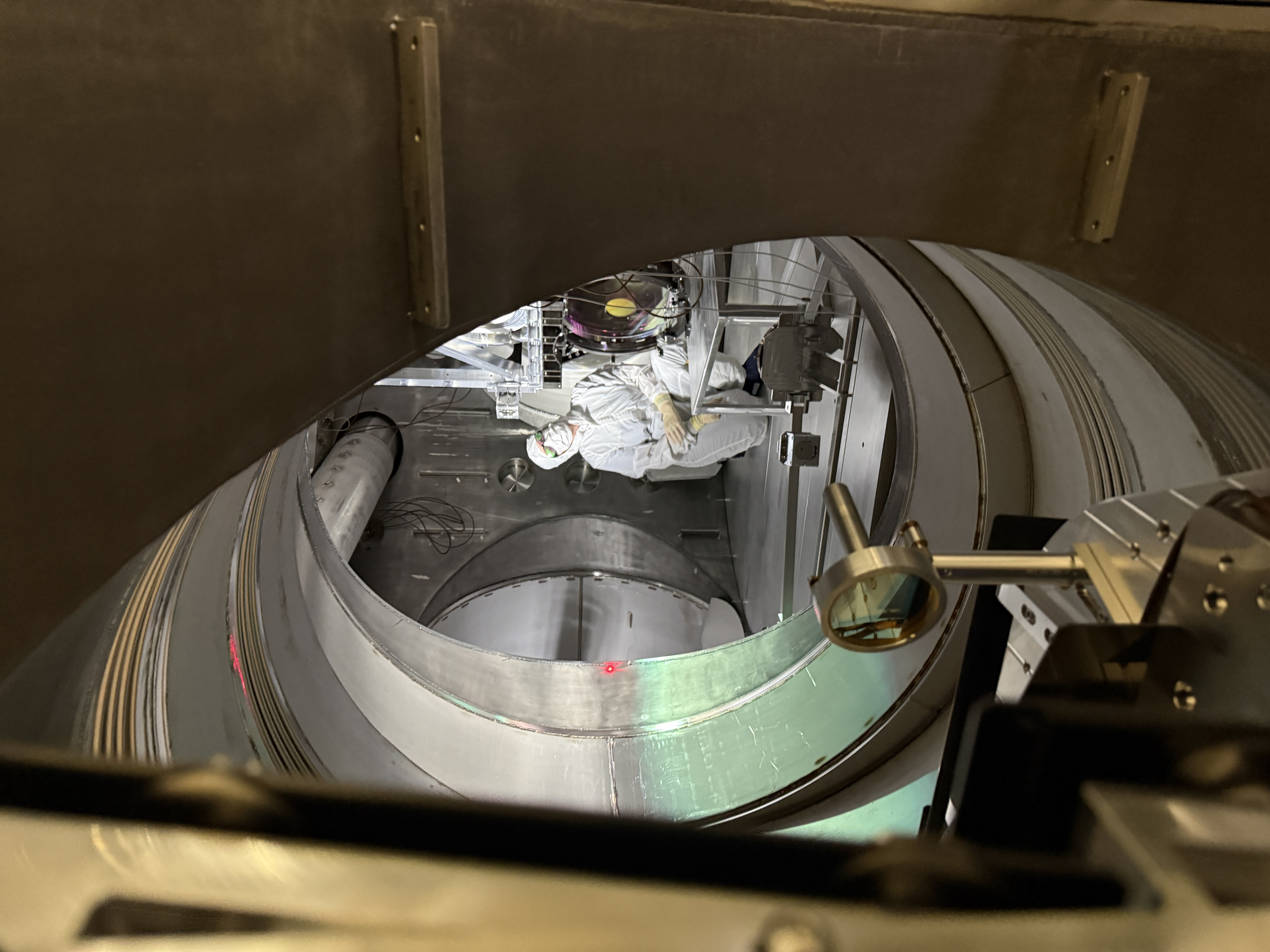
As noted in LHO alog 90665, we are seeing strong pitch yaw coupling on the BBS, when actuating via the top stage QOSEM coils. When we try and adjust the optic yaw we see a 1:5 response in pitch and vice versa. This is seen in both the QOSEM readouts, and visually using an IR beamcard on the PSL beam bouncing off the optic.
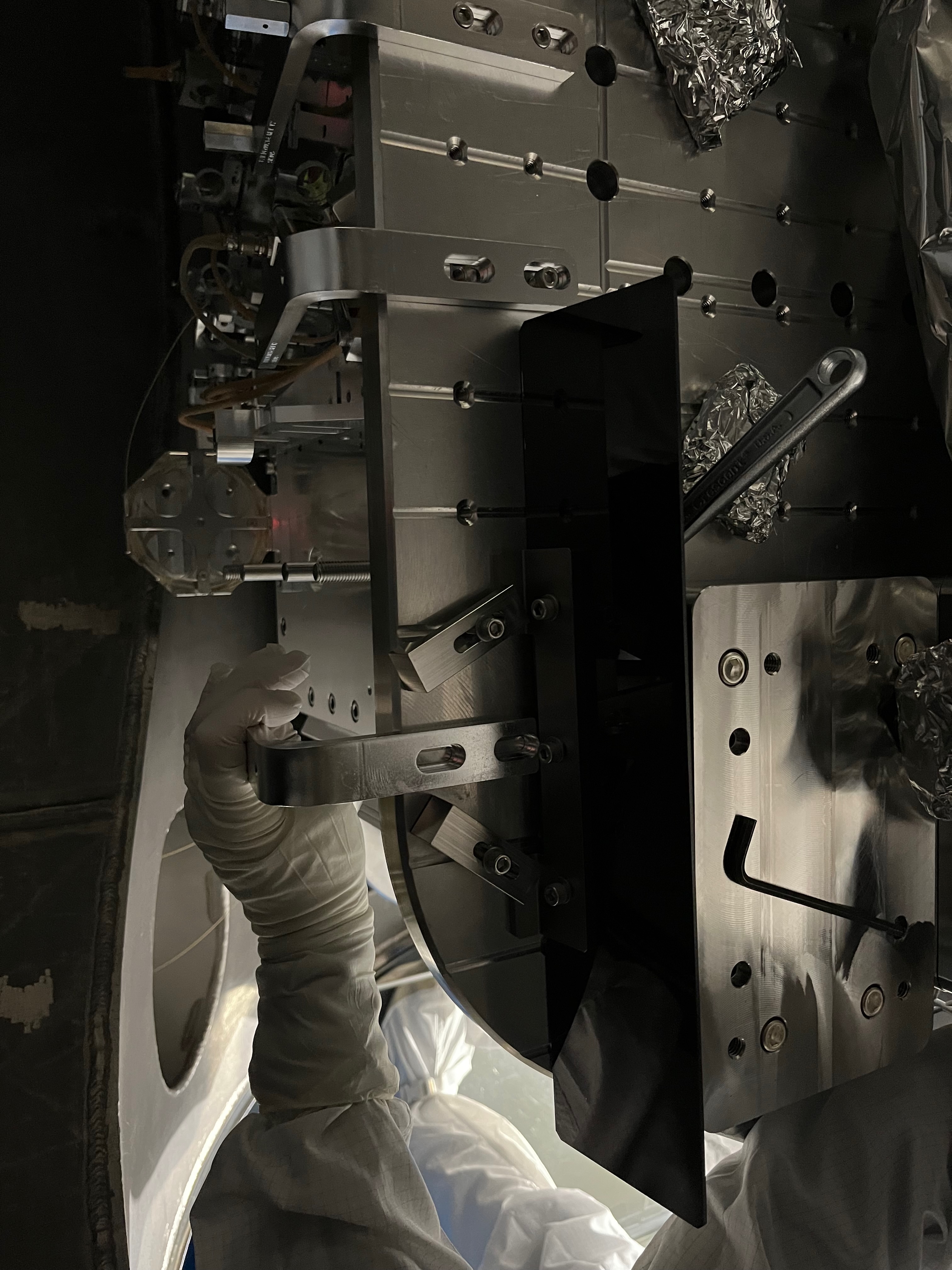
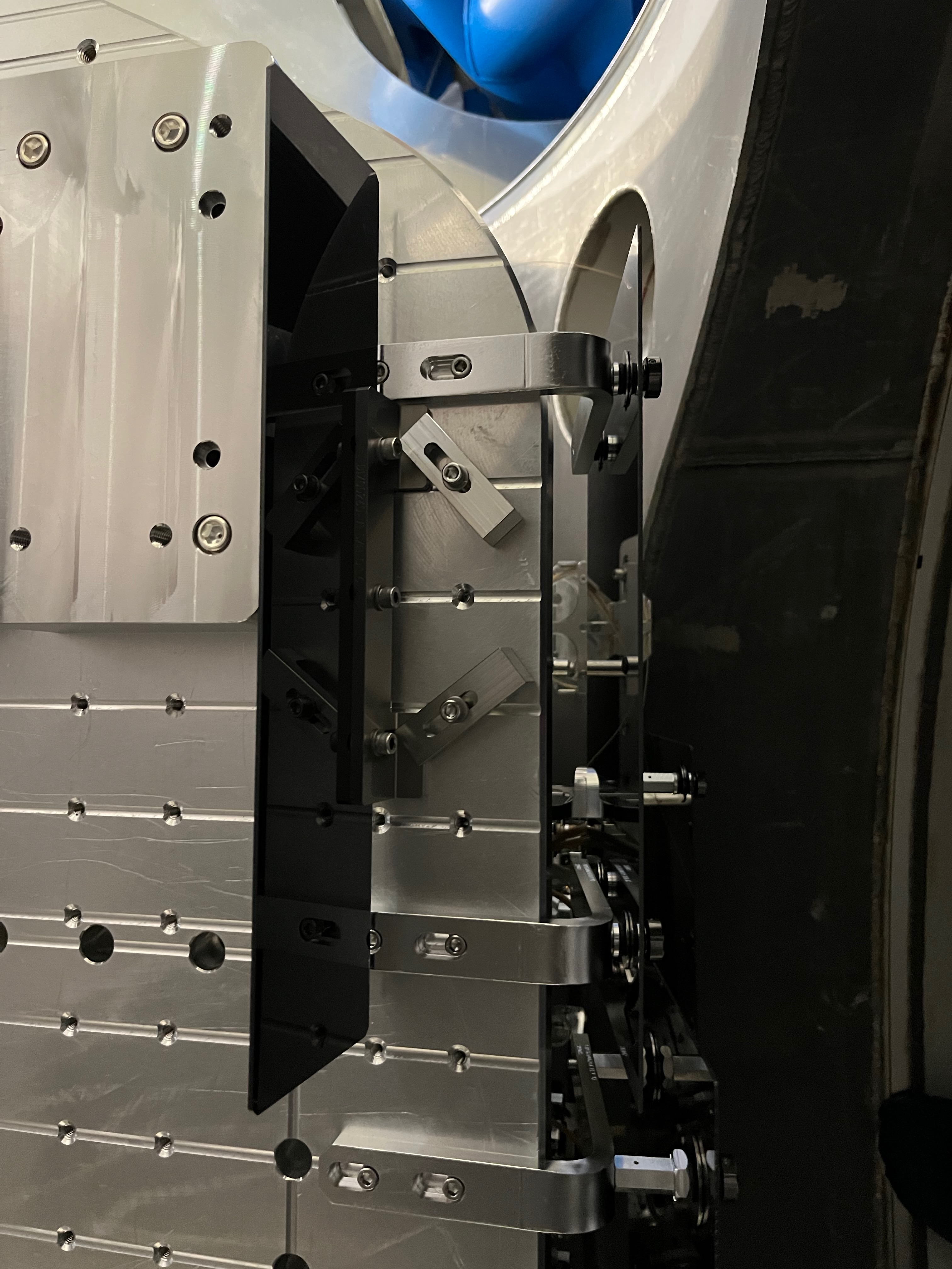
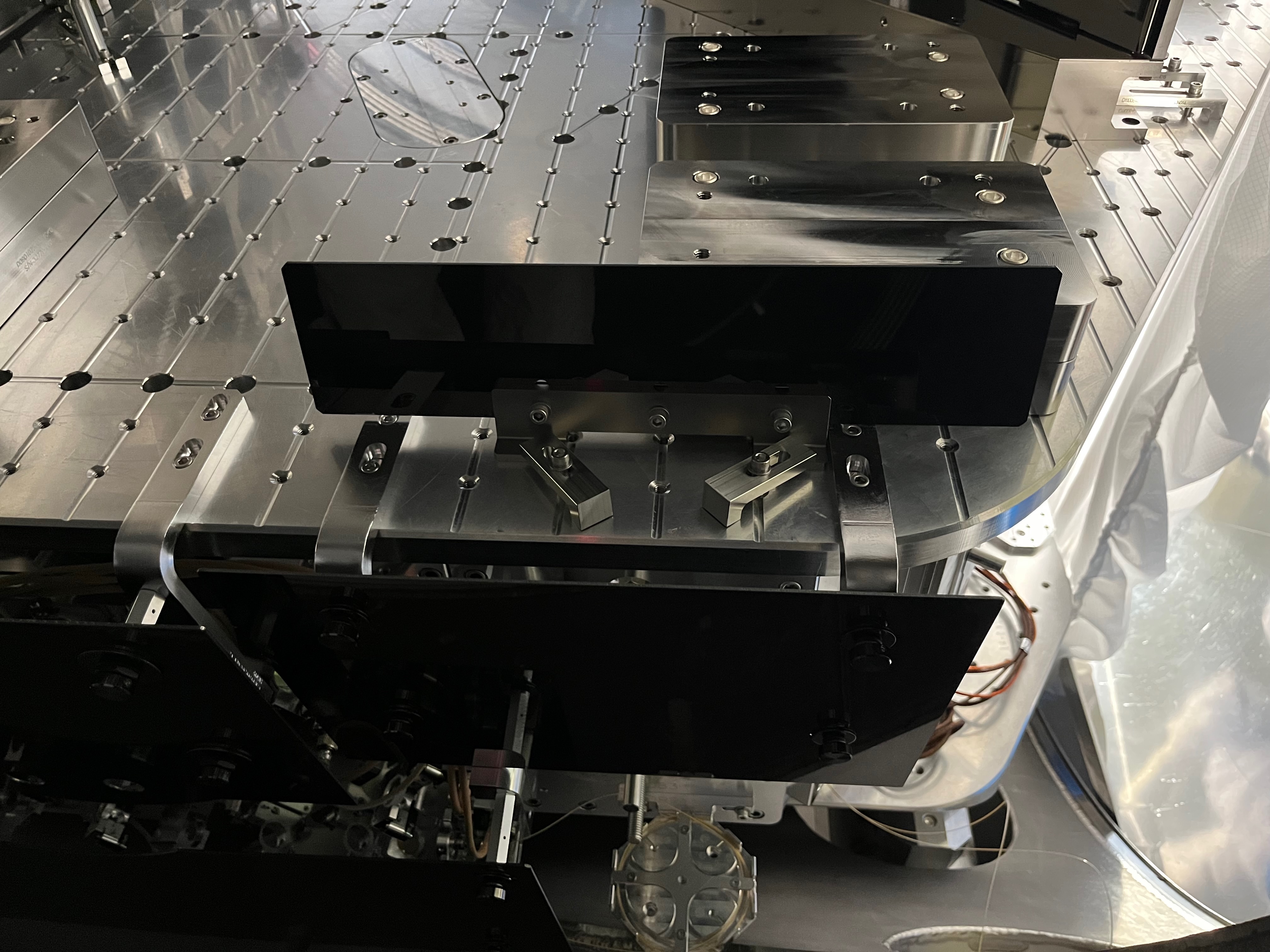
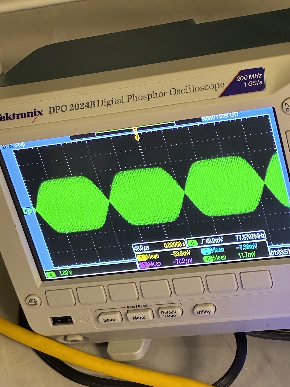
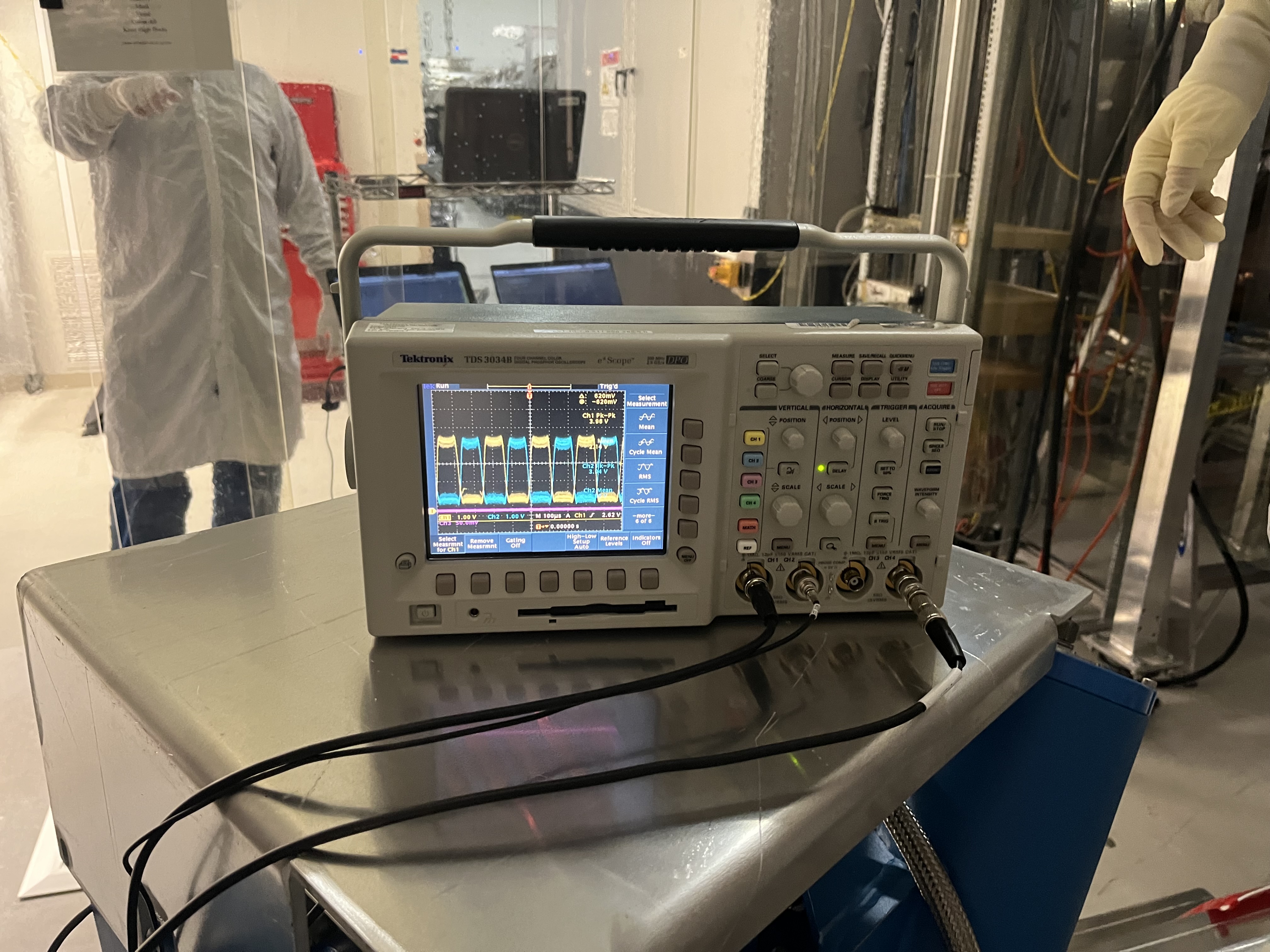
To investigate whether the cause was electronic in nature, we went into chamber to ensure that only the F2 and F3 QOSEM coils are being driven when requesting yaw drive. We used a multimeter to measure the voltage drop across the coils, to determine whether theyre being driven or not. As we expected, only the F2 and F3 coils are being driven, with equal and opposite magnitude, when trying to drive yaw. This suggests that this coupling is not coming from the coil electronics chain, or an issue in CDS.


