TITLE: 07/01 Eve Shift: 2330-0500 UTC (1630-2200 PST), all times posted in UTC
STATE of H1: Preventive Maintenance
OUTGOING OPERATOR: Corey
CURRENT ENVIRONMENT:
SEI_ENV state: CALM
Wind: 18mph Gusts, 11mph 3min avg
Primary useism: 0.02 μm/s
Secondary useism: 0.05 μm/s
QUICK SUMMARY: H1 has just relocked following the maintenance period today, but currently waiting in OMC_WHITENING to damp some very rung-up violin modes. Meanwhile, Elenna is running jitter noise injections. I'm also aware of the OPO crystal move from today, so I'll be watching SQZ performance this evening and will adjust the temperature if need be.
FAMIS 28412, last ran and analyzed in alog85311
The analysis for this week's ITMX measurements failed again, same as last week, due to too low of coherence (0.01219488098759549, which is below the threshold of 0.1), so there's not a new data point for the ITMX plot. All other QUAD's analyses ran without issue.
Camilla, TJ, Dave:
Last Thursday 26th June 2025 alog85373 I restarted the HWS camera control code. We hoped this would improve the 2Hz noise comb in DARM. Initial results for F-Scan (observing) suggest it has not made much, if any difference.
Attached F-Scans show the spectra on sun22jun2025 and mon30jun2025. The 2Hz comb (blue squares) look unchanged.
More investigation is needed to verfiy we are indeed disabling the frame aquisition on all HWS cameras when H1 is in observation.
Looking at the HWS camera data, Dave's code was successfully stopping the HWS camera dueing NLN from 27th June, as expected 85373.
However, looking at the f-scans from the last week, the 2Hz comb was there until 3rd July but was gone on 4th July and hasn't returned since.
Nothing HWS related should have changed on the 3rd July (ops shift log 85519).
Excellent, thank you Camilla and Dave! This is very helpful.
WP12649 Add h1ascimc WFS_B_DC chans to DAQ
Elenna, Dave:
A new h1ascimc model was installed which adds two 16kHz versions of the WFS_B_DC channels to the DAQ. The new channels are
H1:IMC-WFS_B_DC_[PIT,YAW]_OUT_16K_DQ
A DAQ restart was required.
WP12635 VACSTAT HAM1 update
Dave:
A new H1EPICS_VACSTAT.ini was generated. This removes the temporary H1-PT100B VACSTAT gauge and adds the new HAM1 PT100_MOD2 gauge to the DAQ. After the EDC+DAQ restart, VACSTAT was restarted sans H1-PT100B now it is longer needed by EDC.
WP12637 HWS Camera Control
Dave
As part of getting the HWS camera control system running again, its new IOC was added to the EDC via H1EPICS_HWSCAMCTRL.ini. EDC+DAQ restart was needed
DAQ Restart
Dave, Jonathan, Erik
DAQ was restarted for four changes:
1) New H1ASCIMC.ini, adding two new fast DQ channels.
2) New H1EPICS_VACSTAT.ini, removing obsolete VACSTAT chans associated with H1-PT100B
3) Removed H1EPICS_VACHAM1.ini, which was trending the temporary H1 version ot PT100B
4) Added new H1EPICS_HWSCAMCTRL, new HWS camera control's IOC non-string channels.
This was a very messy restart.
After restarting the h1ascimc model, the 0-leg was restarted. A second restart of GDS0 was needed.
After writing two full frames, FW0 crashed and restarted itself.
Once FW0 was back, the 1-leg was restarted. GDS1 needed a second restart.
About 10 minutes later, FW0 had a second crash. This is not unheard of, but very rare.
In the course of investigating it was discovered that FW1 had an unused 1TB Seagate HDD (sda) which has been generating errors over the past month. We decided to remove this from h1daqfw1 since it served no purpose.
Following the DAQ restart, item 2) removal means I can stop running the temporary EPICS IOC vac_ham1_pressure_converter_ioc. This code no longer runs on opslogin0 in a tmux session.
WP12651 Replace h1seih23 IO Chassis +24VDC power supply
Fil, Marc, Erik, Dave:
h1seih23 was fenced and powered down. The IO Chassis was then powered down and its +24VDC supply was replaced (bad fan bearing). System was powered back up with no issues.
Tue01Jul2025
LOC TIME HOSTNAME MODEL/REBOOT
12:30:40 h1asc0 h1ascimc <<< new model
12:33:47 h1daqdc0 [DAQ] <<< 0-leg restart
12:34:00 h1daqfw0 [DAQ]
12:34:00 h1daqtw0 [DAQ]
12:34:01 h1daqnds0 [DAQ]
12:34:08 h1daqgds0 [DAQ]
12:34:12 h1susauxb123 h1edc[DAQ] <<< EDC restart, VACSTAT, H1-PT100B, HWSCAMCTRL
12:35:18 h1daqgds0 [DAQ] <<< 2nd GDS0 restart
12:38:34 h1daqfw0 [DAQ] <<< FW0 First Crash
12:42:18 h1daqdc1 [DAQ] <<< 1-leg restart
12:42:29 h1daqfw1 [DAQ]
12:42:30 h1daqtw1 [DAQ]
12:42:32 h1daqnds1 [DAQ]
12:42:40 h1daqgds1 [DAQ]
12:43:42 h1daqgds1 [DAQ] <<< 2nd GDS1 restart
13:02:52 h1daqfw0 [DAQ] <<< FW0 Second Crash
13:42:22 h1daqfw1 [DAQ] <<< FW1 restarted to remove faulty sda HDD
14:00:38 h1seih23 h1iopseih23 <<< h1seih23 front end power cycle to replace DC power supply
14:00:51 h1seih23 h1hpiham2
14:01:04 h1seih23 h1hpiham3
14:01:17 h1seih23 h1isiham2
14:01:30 h1seih23 h1isiham3
DAQ Changes (NAME, TYPE, RATE)
+ H1:CDS-HWS_CAM_CTRL_ETMX_GPS 4 16
+ H1:CDS-HWS_CAM_CTRL_ETMX_START_GPS 4 16
+ H1:CDS-HWS_CAM_CTRL_ETMX_STATUS 4 16
+ H1:CDS-HWS_CAM_CTRL_ETMX_UPTIME_SEC 4 16
+ H1:CDS-HWS_CAM_CTRL_ETMY_GPS 4 16
+ H1:CDS-HWS_CAM_CTRL_ETMY_START_GPS 4 16
+ H1:CDS-HWS_CAM_CTRL_ETMY_STATUS 4 16
+ H1:CDS-HWS_CAM_CTRL_ETMY_UPTIME_SEC 4 16
+ H1:CDS-HWS_CAM_CTRL_ITMX_GPS 4 16
+ H1:CDS-HWS_CAM_CTRL_ITMX_START_GPS 4 16
+ H1:CDS-HWS_CAM_CTRL_ITMX_STATUS 4 16
+ H1:CDS-HWS_CAM_CTRL_ITMX_UPTIME_SEC 4 16
+ H1:CDS-HWS_CAM_CTRL_ITMY_GPS 4 16
+ H1:CDS-HWS_CAM_CTRL_ITMY_START_GPS 4 16
+ H1:CDS-HWS_CAM_CTRL_ITMY_STATUS 4 16
+ H1:CDS-HWS_CAM_CTRL_ITMY_UPTIME_SEC 4 16
+ H1:CDS-VAC_STAT_LX_X0_PT100_MOD2_CONN_VALID 4 16
+ H1:CDS-VAC_STAT_LX_X0_PT100_MOD2_ENABLED 4 16
+ H1:CDS-VAC_STAT_LX_X0_PT100_MOD2_GLITCH 4 16
+ H1:CDS-VAC_STAT_LX_X0_PT100_MOD2_GLITCH_GPS 4 16
+ H1:CDS-VAC_STAT_LX_X0_PT100_MOD2_LIVE_DELTAP_300 4 16
+ H1:CDS-VAC_STAT_LX_X0_PT100_MOD2_LIVE_DELTAP_60 4 16
+ H1:CDS-VAC_STAT_LX_X0_PT100_MOD2_LIVE_DELTAP_600 4 16
+ H1:CDS-VAC_STAT_LX_X0_PT100_MOD2_LIVE_DELTAP_TRIP_300 4 16
+ H1:CDS-VAC_STAT_LX_X0_PT100_MOD2_LIVE_DELTAP_TRIP_60 4 16
+ H1:CDS-VAC_STAT_LX_X0_PT100_MOD2_LIVE_DELTAP_TRIP_600 4 16
+ H1:CDS-VAC_STAT_LX_X0_PT100_MOD2_LIVE_INTERCEPT_300 4 16
+ H1:CDS-VAC_STAT_LX_X0_PT100_MOD2_LIVE_INTERCEPT_60 4 16
+ H1:CDS-VAC_STAT_LX_X0_PT100_MOD2_LIVE_INTERCEPT_600 4 16
+ H1:CDS-VAC_STAT_LX_X0_PT100_MOD2_LIVE_SLOPE_300 4 16
+ H1:CDS-VAC_STAT_LX_X0_PT100_MOD2_LIVE_SLOPE_60 4 16
+ H1:CDS-VAC_STAT_LX_X0_PT100_MOD2_LIVE_SLOPE_600 4 16
+ H1:CDS-VAC_STAT_LX_X0_PT100_MOD2_LIVE_SLOPE_TRIP_300 4 16
+ H1:CDS-VAC_STAT_LX_X0_PT100_MOD2_LIVE_SLOPE_TRIP_60 4 16
+ H1:CDS-VAC_STAT_LX_X0_PT100_MOD2_LIVE_SLOPE_TRIP_600 4 16
+ H1:CDS-VAC_STAT_LX_X0_PT100_MOD2_OPERATIONAL 4 16
+ H1:CDS-VAC_STAT_LX_X0_PT100_MOD2_VALID 4 16
+ H1:CDS-VAC_STAT_LX_X0_PT100_MOD2_VALUE 4 16
+ H1:CDS-VAC_STAT_LX_X0_PT100_MOD2_VAL_VALID 4 16
- H1:CDS-VAC_STAT_LY_X0_PT100B_CONN_VALID 4 16
- H1:CDS-VAC_STAT_LY_X0_PT100B_ENABLED 4 16
- H1:CDS-VAC_STAT_LY_X0_PT100B_GLITCH 4 16
- H1:CDS-VAC_STAT_LY_X0_PT100B_GLITCH_GPS 4 16
- H1:CDS-VAC_STAT_LY_X0_PT100B_LIVE_DELTAP_300 4 16
- H1:CDS-VAC_STAT_LY_X0_PT100B_LIVE_DELTAP_60 4 16
- H1:CDS-VAC_STAT_LY_X0_PT100B_LIVE_DELTAP_600 4 16
- H1:CDS-VAC_STAT_LY_X0_PT100B_LIVE_DELTAP_TRIP_300 4 16
- H1:CDS-VAC_STAT_LY_X0_PT100B_LIVE_DELTAP_TRIP_60 4 16
- H1:CDS-VAC_STAT_LY_X0_PT100B_LIVE_DELTAP_TRIP_600 4 16
- H1:CDS-VAC_STAT_LY_X0_PT100B_LIVE_INTERCEPT_300 4 16
- H1:CDS-VAC_STAT_LY_X0_PT100B_LIVE_INTERCEPT_60 4 16
- H1:CDS-VAC_STAT_LY_X0_PT100B_LIVE_INTERCEPT_600 4 16
- H1:CDS-VAC_STAT_LY_X0_PT100B_LIVE_SLOPE_300 4 16
- H1:CDS-VAC_STAT_LY_X0_PT100B_LIVE_SLOPE_60 4 16
- H1:CDS-VAC_STAT_LY_X0_PT100B_LIVE_SLOPE_600 4 16
- H1:CDS-VAC_STAT_LY_X0_PT100B_LIVE_SLOPE_TRIP_300 4 16
- H1:CDS-VAC_STAT_LY_X0_PT100B_LIVE_SLOPE_TRIP_60 4 16
- H1:CDS-VAC_STAT_LY_X0_PT100B_LIVE_SLOPE_TRIP_600 4 16
- H1:CDS-VAC_STAT_LY_X0_PT100B_OPERATIONAL 4 16
- H1:CDS-VAC_STAT_LY_X0_PT100B_VALID 4 16
- H1:CDS-VAC_STAT_LY_X0_PT100B_VALUE 4 16
- H1:CDS-VAC_STAT_LY_X0_PT100B_VAL_VALID 4 16
+ H1:IMC-WFS_B_DC_PIT_OUT_16K_DQ 4 16384
+ H1:IMC-WFS_B_DC_YAW_OUT_16K_DQ 4 16384
- H1:VAC-LY_X0_PT100B_GPS_TIME 4 16
- H1:VAC-LY_X0_PT100B_PRESS_TORR 4 16
- H1:VAC-LY_X0_PT100B_UPTIME 4 16
FAMIS 25806
pH of PSL chiller water was measured to be between 10.0 and 10.5 according to the color of the test strip.
E. Capote, J. Kissel, A. Sanchez, D. Barker, E. von Reis
Per WP#12649, the ASCIMC model was updated. Two test points were added to the IMC-WFS_B_{PIT,YAW}_OUT outputs that were then DQed to 16k, see attached screenshot of the new testpoints. These channels are being saved at the higher rate so they can be used as jitter witnesses, see attached screenshot of the channel list. The new channel names are "IMC-WFS_B_{PIT,YAW}_16K_OUT". Erik helped me set up these new test points, and Dave took care of the model and DAQ restart.
Before the model restart, I had checked the ASCIMC model and saw no SDF differences, so I assumed that we were good to go to restart the model. Here are two errors I made:
Once the restart had happened, and SDF reverted, the IMC came back very poorly aligned. Jeff and Tony had to move the IMC PZT offset by "hundreds of counts" to get us back to a good enough alignment to lock. After that, Jeff, Tony, and I proceeded to engage the IMC WFS, and turned up the WFS gain to 0.5 to help the loops converge faster. Once they converged, we took the IMC guardian to "MCWFS offloaded". Here, we made another mistake by forgetting to accept the PZT offsets in SDF, so when ISC_LOCK went through the "SDF revert" state, the offsets were set to some old value, which put the IMC back in a bad alignment. We repeated the process again, and this time remembered to save the new offsets in the SDF. I have attached a screenshot of this change.
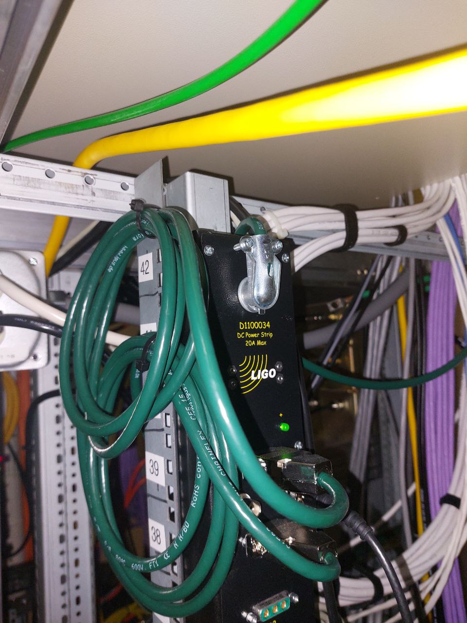
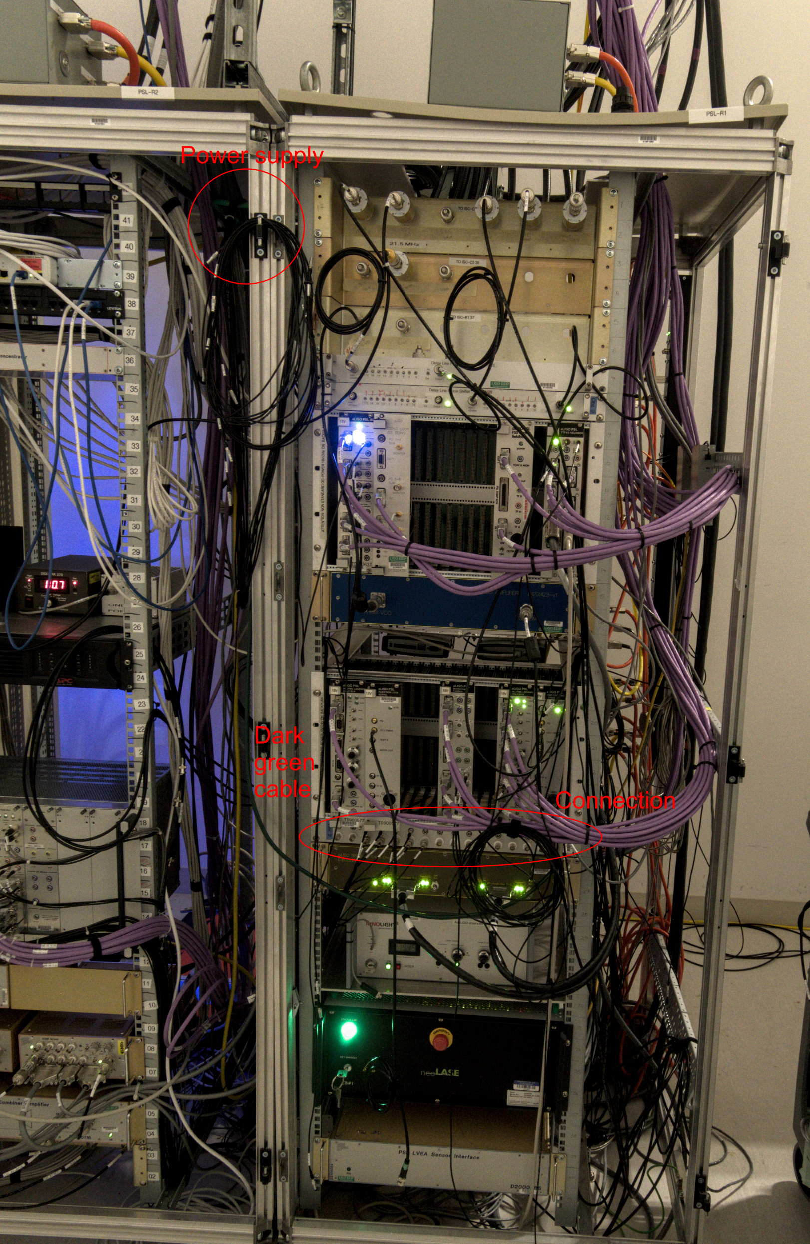
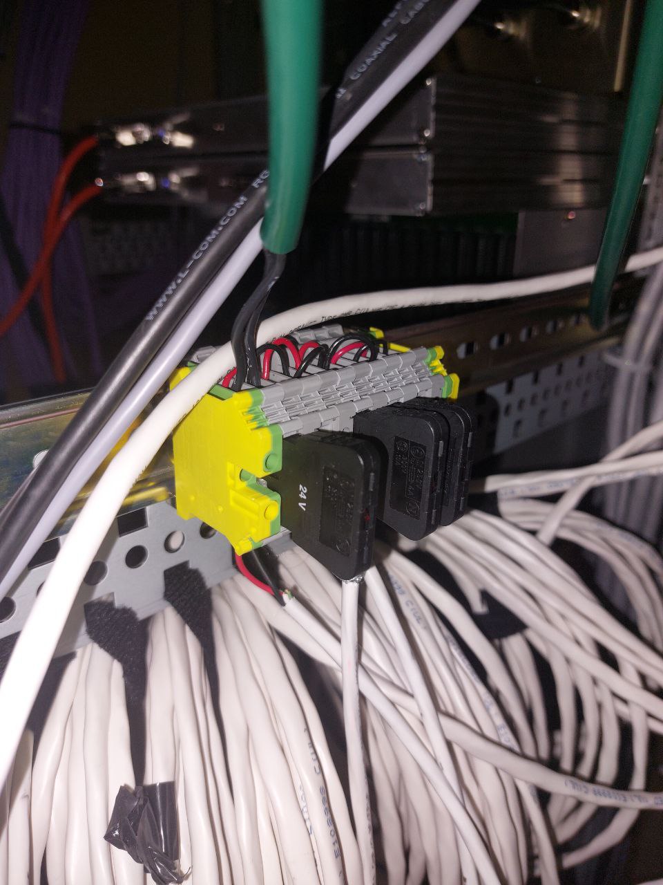
Per WP12651 we investigated and replaced the IO Chassis supply for H1SEI23 which supports seismic on HAM 2 & 3. This supply is located in Mezanine rack C3, location U2 Right Side, provides +24V, and measured ~3.5A draw. The fan was chirping and grinding which suggests a failing fan bearing.
Old Supply = S1202002 old fan worn out bearing to be refurbished.
New Supply = S1201919 new fan with ball bearing.
F. Clara
M. Pirello
J. Kissel, O. Patane, F. Clara ECR E2400330 Calling this out explicitly: We have changed the OSEM PD satellite amplifiers on H1SUSPRM, H1SUSPR3, H1SUSBS, H1SUSSR3, and H1SUSSRM top masses; see LHO:85463 We chose to implement ECR E2400330 by modifying spare chassis ahead of time, and installing those modified spares in place of the old chassis (which will become some other suspensions' "new" amps next week). Though the ECR only changes the whitening stage frequency response. However, because the old vs. new chasses have different set of other overall transimpedance gain determining components, the read-back for the OSEM PDs will likely change slightly. Thus, the OSEMs' recast as EULER basis signals will also change slightly, *looking* like an alignment change, even though the alignment of the physical suspension will NOT have changed. This won't be in any consistent direction, and the transimpedance gain is determined by components that have value at any value within the components' tolerance. I attach two examples, H1SUSPR3 and H1SUSBS, of the levels we're talking about -- In the OSEM basis, it's 1-3 [urad], and same in the EULER basis. For the beam splitter, a physical change in alignment of that magnitude would be significant, hence me bringing it up explicitly. So, the new normal for the following suspension alignment starts on 2025-07-01 12:30 UTC: H1SUSPRM H1SUSPR3 H1SUSBS H1SUSSR3 H1SUSSRM We'll definitely have to re-run initial alignment after today's maintenance day, given that (unrelated) - we rebooted the entire electronics racks at EY to replace failing power supplies, - we rebooted the seih23 - we adjusted the green camera alignment
We noticed a failed drive on h1daqfw1. As we were in maintenance we powered down the system and removed the disk. This was a 1TB spinning disk. It was most likely put in to allow us to have large storage if we needed to write frames locally and then move then over the network, this was a very real posibility at point. However we never ended up doing that.
The system was taken down at around 13:38 local time.
F. Clara, E. Capote
Per WP#12646, Fil and I went out to the floor and realigned the ITMX green camera, as Sheila noted it was poorly aligned in alog 84819. (Before we began, Corey transitioned the LVEA to laser hazard per WP#12647).
Before going out to align, I locked the X arm in green only using the camera offsets for the alignment. I offloaded this X arm alignment, so it could be preserved once we moved the camera.
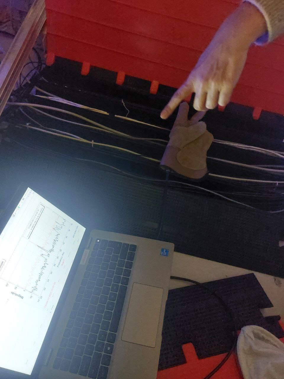
With the X arm still locked, Fil and I connected a computer to the green camera output, which gave us a faster, live view of the camera as we adjusted it. Fil used a Rainbow controller to zoom out very far to reduce our chances of moving the beam too much and losing it. Fil then removed the camera housing cover, and adjusted the nobs on the camera. As he adjusted in the desired direction, I zoomed the camera in slowly, to ensure that we were moving the beam closer to center. We iterated this process several times. The first time Fil went to put the camera cover back on, we noticed that the action of placing the cover bumped the aligment a little bit, so we had to overcorrect in the opposite direction slightly so that the beam stayed centered as Fil replaced the cover. I then tried adjusted the zoom and lens slightly, and decided that the image was well-centered enough to finish the work.
Once we were back in the control room, I updated the camera offsets. I have attached the SDF of these new offsets.
We took open loop transfer functions for some suspensions today. Some were taken so we have 'before' OLG and loop suppression data before we switch out their satamps (ITMX, ITMY), and the rest were after the satamps were switched out (85463) so that we could confirm that they all looked good (PRM, PR3, SRM, SR3).
0.4:10 (old) satamp OLG TFs
ITMX M0
- Measurements taken with suspension in HEALTH_CHECK but with damping loops on
- optic align offsets off, L2->R0 damping off, etc
- We needed to adjust the excitation filters for V and Y, plus lower the amplitude by a factor of at least 5x to keep the suspension dac from overflowing and saturating. These excitation filters were originally matches to the ETM ones, but we had to adjust them.
Data: 2025-07-01_1645_H1SUSITMX_M0_WhiteNoise_{L,T,V,R,P,Y}_0p01to50Hz_OpenLoopGainTF.xml r12366
ITMY M0
- Measurements taken with suspension in HEALTH_CHECK but with damping loops on
- optic align offsets off, L2->R0 damping off, etc
- We needed to adjust the excitation filters for V and Y, plus lower the amplitude by a factor of at least 5x to keep the suspension dac from overflowing and saturating. These excitation filters were originally matches to the ETM ones, but we had to adjust them.
- When trying take Y, there was noise affecting mainly F1/F2/F3 (ndscope1, ndscope2) that was happening every ~4mins. Every time it happened it would cause overflows as well. This made it really hard to get a Y measurement, so the Y here looks pretty bad. We can try another time to get the data for Y. We don't know why this was happening but it stopped once we left HEALTH_CHECK (but it didn't start when we first entered HEALTH_CHECK)
Data: 2025-07-01_1700_H1SUSITMY_M0_WhiteNoise_{L,T,V,R,P,Y}_0p01to50Hz_OpenLoopGainTF.xml r12369
0.1:5 (new) satamp OLG TFs
Note: for all of the following measurements, the OSEMINF FM1 filter had been updated from 10.4:0.38 to 5.31:0.0969 to match the new 0.0969:5.31 satamp (85471)
PRM M1
- Measurements taken with suspension in HEALTH_CHECK but with damping loops on
- optic align offsets off, etc
- We needed to increase the exc gain to match the decrease in damping loop gain (-0.5)
Data: 2025-07-01_1815_H1SUSPRM_M1_CDBIOState_1_WhiteNoise_{L,T,V,R,P,Y}_0p01to100Hz_OpenLoopGainTF.xml r12368
PR3 M1
- Measurements taken with suspension in HEALTH_CHECK but with damping loops on
- optic align offsets off, etc
- We found that some dofs were being very underdriven, so we upped the gain by 10 or 100x
Data: 2025-07-01_1820_H1SUSPR3_M1_WhiteNoise_{L,T,V,R,P,Y}_0p02to50Hz_OpenLoopGainTF.xml r12367
SRM M1
- Measurements taken with suspension in HEALTH_CHECK but with damping loops on AND optic align offsets ON
- We needed to increase the exc gain to match the decrease in damping loop gain (-0.5)
Data: 2025-07-01_1900_H1SUSSRM_M1_WhiteNoise_{L,T,V,R,P,Y}_0p02to50Hz_OpenLoopGainTF.xml r12372
SR3 M1
- Measurements taken with suspension in HEALTH_CHECK but with damping loops on
- optic align offsets off, etc
- We found that some dofs were being very underdriven, so we upped the gain by 10 or 100x
Data: 2025-07-01_1830_H1SUSSR3_M1_WhiteNoise_Y_0p02to50Hz_OpenLoopGainTF.xml r12371
Main takeaways:
- ITMY Y was bad due to some strange mystery noise and needs to be retaken
- PRM, PR3, SRM, SR3 all had new satamps and updated OSEMINF FM1 filters to match
- SRM measurements were taken with optic align offsets ON
To finish off Fil's work for ECR E2400330 replacing the M1 satamps for BS, PRM, PR3, SRM, and SR3, I replaced FM1 in their OSEMINF filter banks from being z:p = 10:0.4 to z:p = 5.31:0.0969 to properly compensate for the new satamp. I've attached the filter file diffs for each suspension. They've all been loaded in.
The new EX purge air compressor and drying skid were turned on this morning at ~8am and dewpoint and particulate measurements were taken at ~11:30am. See attached pics of the dewpoint monitor at the exhaust of the drying tower, dewpoint at the coupling fitting at the EX spool just upstream of BSC9, and particulate counts at the same spool coupling. FTIR sample was taken of the coupling fitting and will be stored onsite.
WP 12640
ECR E2400330
Drawing D0901284-v5
T2500232
Today we started upgrading the SUS Sat Amps per ECR E2400330. Modification improves the whitening stage to reduce ADC noise from 0.05 to 10 Hz. The following units were replaced with modified units:
Suspension | Old | New |
PRM TOP | S1100067 | S1100168 |
PRM/PR3 | S1000275 | S1100173 |
PR3 | S1100175 | S1100183 |
BS TOP | S1100090 | S1000291 |
BS RT/SD | S1100155 | S1100066 |
SR3 Top | S1000296 | S1000284 |
SR3/SRM | S1100178 | S1000290 |
SRM | S1100136 | S1100068 |
F. Clara, C. Gray, J. Kissel, O. Patane, M.Pirello
Here's the characterization data and fit results for S1100168, assigned to PRM M1's T1T2T3LF OSEMs (what Fil refers to as just "PRM TOP" above). The data was taken per methods described in T080062-v3. The data was processed and fit using ${SusSVN}/trunk/electronicstesting/lho_electronics_testing/satamp/ECR_E2400330/Scripts/ plotresponse_S1100168_PRM_M1_T1T2T3LF_20250630.m Explicitly, the fit to the whitening stage zero and pole, the transimpedance feedback resistor, and foton design string are Optic Stage Serial_Number Channel_Number OSEM_Name Zero_Pole_Hz R_TIA_kOhm Foton_Design PRM M1 S1100168 CH1 T1 0.0969 : 5.30 120.10 zpk([5.3],[0.0969],1,"n") CH2 T2 0.0950 : 5.20 120.25 zpk([5.2],[0.095],1,"n") CH3 T3 0.0950 : 5.18 120.25 zpk([5.18],[0.095],1,"n") CH4 LF 0.0940 : 5.15 120.00 zpk([5.15],[0.094],1,"n") The attached plot and machine readable .txt file are also found in ${SusSVN}/trunk/electronicstesting/lho_electronics_testing/satamp/ECR_E2400330/Scripts/ Even though I've fit for the transimpedance gain, I've elected *not* to include a gain in the foton design string relative to "ideal," as there are more scale factors in play that determine the overall [(meters)/(ADC cts)] scale in the calibration of the OSEMs (LED light power, PD response, any cable loss, ADC channel gain, etc.). Determining this overall scale is better left to different methods, a la LHO:84548, which we (eventually) anticipate doing for all SUS with ECR E2400330 upgraded satamps.
Here's the characterization data and fit results for S1100173 , assigned to PRM/PR3 M1's RTSD/T1T2 OSEMs (what Fil refers to as just "PRM/PR3" above). The data was taken per methods described in T080062-v3. The data was processed and fit using ${SusSVN}/trunk/electronicstesting/lho_electronics_testing/satamp/ECR_E2400330/Scripts/ plotresponse_S1100173_PRMPR3_M1_RTSDT1T2_20250630.m Explicitly, the fit to the whitening stage zero and pole, the transimpedance feedback resistor, and foton design string are Optic Stage Serial_Number Channel_Number OSEM_Name Zero_Pole_Hz R_TIA_kOhm Foton_Design PRMPR3 M1 S1100173 CH1 RT 0.0969 : 5.3 120.00 zpk([5.3],[0.0969],1,"n") CH2 SD 0.0955 : 5.22 120.00 zpk([5.22],[0.0955],1,"n") CH3 T1 0.0975 : 5.35 119.75 zpk([5.35],[0.0975],1,"n") CH4 T2 0.0975 : 5.33 120.25 zpk([5.33],[0.0975],1,"n") The attached plot and machine readable .txt file version of the above table are also found in ${SusSVN}/trunk/electronicstesting/lho_electronics_testing/satamp/ECR_E2400330/Scripts/ See above LHO:85504 comment as to why an account of the fit transimpedance was not included in the foton design string gain.
Here's the characterization data and fit results for S1100183 , assigned to PR3 M1's T3LFRTSD OSEMs (what Fil refers to as just "PR3" above). The data was taken per methods described in T080062-v3. The data was processed and fit using ${SusSVN}/trunk/electronicstesting/lho_electronics_testing/satamp/ECR_E2400330/Scripts/ plotresponse_S1100183_PR3_M1_T3LFRTSD_20250630.m Explicitly, the fit to the whitening stage zero and pole, the transimpedance feedback resistor, and foton design string are Optic Stage Serial_Number Channel_Number OSEM_Name Zero_Pole_Hz R_TIA_kOhm Foton_Design PR3 M1 S1100183 CH1 T3 0.0950 : 5.19 120 zpk([5.19],[0.095],1,"n") CH2 LF 0.0945 : 5.17 120 zpk([5.17],[0.0945],1,"n") CH3 RT 0.0940 : 5.14 120 zpk([5.14],[0.094],1,"n") CH4 SD 0.0955 : 5.24 120 zpk([5.24],[0.0955],1,"n") The attached plot and machine readable .txt file version of the above table are also found in ${SusSVN}/trunk/electronicstesting/lho_electronics_testing/satamp/ECR_E2400330/Scripts/ See above LHO:85504 comment as to why an account of the fit transimpedance was not included in the foton design string gain.
Here's the characterization data and fit results for S1000291 , assigned to BS M1's F1F2F3LF OSEMs (what Fil refers to as just "BS TOP" above). The data was taken per methods described in T080062-v3. The data was processed and fit using ${SusSVN}/trunk/electronicstesting/lho_electronics_testing/satamp/ECR_E2400330/Scripts/ plotresponse_S1000291_BS_M1_F1F2F3LF_20250630.m Explicitly, the fit to the whitening stage zero and pole, the transimpedance feedback resistor, and foton design string are Optic Stage Serial_Number Channel_Number OSEM_Name Zero_Pole_Hz R_TIA_kOhm Foton_Design BS M1 S1000291 CH1 F1 0.096 : 5.19 121.50 zpk([5.19],[0.096],1,"n") CH2 F2 0.096 : 5.23 120.75 zpk([5.23],[0.096],1,"n") CH3 F3 0.096 : 5.26 120.00 zpk([5.26],[0.096],1,"n") CH4 LF 0.095 : 5.2 120.00 zpk([5.2],[0.095],1,"n") The attached plot and machine readable .txt file version of the above table are also found in ${SusSVN}/trunk/electronicstesting/lho_electronics_testing/satamp/ECR_E2400330/Scripts/ See above LHO:85504 comment as to why an account of the fit transimpedance was not included in the foton design string gain.
Here's the characterization data and fit results for S1100066 , assigned to BS M1's RTSDxxxx OSEMs (with the 2x "xx" representing the unused channels not connected to anything in-vacuum. Fil refers to this as just "BS RT/SD" above). The data was taken per methods described in T080062-v3. The data was processed and fit using ${SusSVN}/trunk/electronicstesting/lho_electronics_testing/satamp/ECR_E2400330/Scripts/ plotresponse_S1100066_BS_M1_RTSDxxx_20250630.m Explicitly, the fit to the whitening stage zero and pole, the transimpedance feedback resistor, and foton design string are Optic Stage Serial_Number Channel_Number OSEM_Name Zero_Pole_Hz R_TIA_kOhm Foton_Design BS M1 S1100066 CH1 RT 0.0960 : 5.19 121.50 zpk([5.19],[0.096],1,"n") CH2 SD 0.0940 : 5.11 120.75 zpk([5.11],[0.094],1,"n") CH3 xx 0.0935 : 5.12 120.25 zpk([5.12],[0.0935],1,"n") CH4 xx 0.0965 : 5.26 120.50 zpk([5.26],[0.0965],1,"n") The attached plot and machine readable .txt file version of the above table are also found in ${SusSVN}/trunk/electronicstesting/lho_electronics_testing/satamp/ECR_E2400330/Scripts/ See above LHO:85504 comment as to why an account of the fit transimpedance was not included in the foton design string gain.
Here's the characterization data and fit results for S1000284 , assigned to SR3 M1's T1T2T3LF OSEMs (Fil refers to this as just "SR3 Top" above). The data was taken per methods described in T080062-v3. The data was processed and fit using ${SusSVN}/trunk/electronicstesting/lho_electronics_testing/satamp/ECR_E2400330/Scripts/ plotresponse_S1000284_SR3_M1_T1T2T3LF_20250630.m Explicitly, the fit to the whitening stage zero and pole, the transimpedance feedback resistor, and foton design string are Optic Stage Serial_Number Channel_Number OSEM_Name Zero_Pole_Hz R_TIA_kOhm Foton_Design SR3 M1 S1000284 CH1 T1 0.0960 : 5.25 120.1 zpk([5.25],[0.096],1,"n") CH2 T2 0.0950 : 5.2 120.1 zpk([5.2],[0.095],1,"n") CH3 T3 0.0960 : 5.27 120.1 zpk([5.27],[0.096],1,"n") CH4 LF 0.0945 : 5.16 120.5 zpk([5.16],[0.0945],1,"n") The attached plot and machine readable .txt file version of the above table are also found in ${SusSVN}/trunk/electronicstesting/lho_electronics_testing/satamp/ECR_E2400330/Scripts/ See above LHO:85504 comment as to why an account of the fit transimpedance was not included in the foton design string gain.
Here's the characterization data and fit results for S1000290 , assigned to SR3/SRM M1's RTSD/T1T2 OSEMs (Fil refers to this as just "SR3/SRM" above). The data was taken per methods described in T080062-v3. The data was processed and fit using ${SusSVN}/trunk/electronicstesting/lho_electronics_testing/satamp/ECR_E2400330/Scripts/ plotresponse_S1000290_SR3SRM_M1_RTSDT1T2_20250630.m Explicitly, the fit to the whitening stage zero and pole, the transimpedance feedback resistor, and foton design string are Optic Stage Serial_Number Channel_Number OSEM_Name Zero_Pole_Hz R_TIA_kOhm Foton_Design SR3/SRM M1 S1000290 CH1 RD 0.0955 : 5.21 120.1 zpk([5.21],[0.0955],1,"n") CH2 SD 0.0940 : 5.13 120.5 zpk([5.13],[0.094],1,"n") CH3 T1 0.0930 : 5.07 120.5 zpk([5.07],[0.093],1,"n") CH4 T2 0.0950 : 5.2 120.1 zpk([5.2],[0.095],1,"n") The attached plot and machine readable .txt file version of the above table are also found in ${SusSVN}/trunk/electronicstesting/lho_electronics_testing/satamp/ECR_E2400330/Scripts/ See above LHO:85504 comment as to why an account of the fit transimpedance was not included in the foton design string gain.
Here's the characterization data and fit results for S1100068 , assigned to SRM M1's T3LFRTSD OSEMs (Fil refers to this as just "SRM" above). The data was taken per methods described in T080062-v3. The data was processed and fit using ${SusSVN}/trunk/electronicstesting/lho_electronics_testing/satamp/ECR_E2400330/Scripts/ plotresponse_S1100068_SRM_M1_T3LFRTSD_20250630.m Explicitly, the fit to the whitening stage zero and pole, the transimpedance feedback resistor, and foton design string are Optic Stage Serial_Number Channel_Number OSEM_Name Zero_Pole_Hz R_TIA_kOhm Foton_Design SRM M1 S1100068 CH1 T3 0.094 : 5.14 120.10 zpk([5.14],[0.094],1,"n") CH2 LF 0.095 : 5.18 120.25 zpk([5.18],[0.095],1,"n") CH3 RT 0.096 : 5.23 120.75 zpk([5.23],[0.096],1,"n") CH4 SD 0.096 : 5.29 119.00 zpk([5.29],[0.096],1,"n") The attached plot and machine readable .txt file version of the above table are also found in ${SusSVN}/trunk/electronicstesting/lho_electronics_testing/satamp/ECR_E2400330/Scripts/ See above LHO:85504 comment as to why an account of the fit transimpedance was not included in the foton design string gain.
Per WP12650 we investigated and replaced two supplies with locked up cooling fans at EY. These supplies service power to the field rack R1 and by extension, the neighboring SUS rack.
We noted the -18V supply in slot U26 on VDC-C1 was running very hot, and when we looked the fan was visibly siezed up. Continuing down the rack, U22 +24V was also siezed up. We replaced both failed supplies with refurbished supplies with upgraded fans. We also lubricated the opposing supplies' fan shafts, +18V and -24V respectively with a drop of lubricant each.
U26L S1203041 +18V was lubricated.
U26R S1201988 -18V was replaced.
U22L S1201929 +24V was replaced.
U22R S1300297 -24V was lubracted.
F. Clara
J. Figueroa
M. Pirello
J. Kissel I've tuned the drive on ALL DOFs of the TMSY open loop gain TF measurement set. Actual results and thoughts will come later, but the templates are /ligo/svncommon/SusSVN/sus/trunk/TMTS/H1/TMSY/SAGM1/Data/ 2025-07-01_1650_H1SUSTMSY_M1_WhiteNoise_L_0p01to50Hz_OpenLoopGainTF.xml 2025-07-01_1650_H1SUSTMSY_M1_WhiteNoise_P_0p01to50Hz_OpenLoopGainTF.xml 2025-07-01_1650_H1SUSTMSY_M1_WhiteNoise_R_0p01to50Hz_OpenLoopGainTF.xml 2025-07-01_1650_H1SUSTMSY_M1_WhiteNoise_T_0p01to50Hz_OpenLoopGainTF.xml 2025-07-01_1650_H1SUSTMSY_M1_WhiteNoise_V_0p01to50Hz_OpenLoopGainTF.xml 2025-07-01_1650_H1SUSTMSY_M1_WhiteNoise_Y_0p01to50Hz_OpenLoopGainTF.xml The SUS was in the HEALTH_CHECK state (alignment offsets OFF), and attached is a screenshot of the damping loop configuration.
WP 12613. ALOG: 84928. "Remove the cabling described in https://alog.ligo-wa.caltech.edu/aLOG/index.php?callRep=84928 from h1brsey and the network switch. Use the video port on h1brsey currently occupied by that cabling to connect to the kvm in the rack instead. Jim noted that "It might have been some sort of kvm or display extension set up Carlos tried for me. The rdp for beckhoff had too much lag to rebalance the BRS, so we had looked at some more direct remote display options, but I don't remember the details." and "the remote adjuster just installed means we don't need it, if that is what it is." Work to be done during any target of opportunity." This work has been completed.
Ivey and Edgard,
We just finshed a fit of the Yaw-to-Yaw transfer functions for the OSEM estimator using the measurements that Oli took for SR3 last Tuesday [see LHO: 85288].
The fits were added to the Sus SVN and live inside '~/SusSVN/sus/trunk/HLTS/Common/FilterDesign/Estimator/fits_H1SR3_2025-06-30.mat' . They are already calibrated to work on the filter banks for the estimator and can be installed using 'make_SR3_yaw_model.m', which lives in the same folder [for reference, see LHO: 84041, where Oli got the fits running for a test].
Attached below are two pictures of the fits we made for the estimator.
The first attachment shows the Suspoint Y to M1 DAMP Y fit. We made sure to fit the asymptotic behavior as well as we could, which ends up being 0.95x10^{-3} um/nm (5% lower than expected from the OSEM calibration). The zpk for this fit is
'zpk([-0.024+20.407i,-0.024-20.407i,-0.044+11.493i,-0.044-11.493i,0,0],[-0.067+21.278i,-0.067-21.278i,-0.095+14.443i,-0.095-14.443i,-0.07+6.405i,-0.07-6.405i],-0.001)'
The second attachment shows the M1 drive Y to M1 DAMP Y fit. We kept the same poles that we had for the other fit, but manually fit the zeros and gain to make a good match. The zpk for this fit is
'zpk([-0.051+8.326i,-0.051-8.326i,-0.011+19.259i,-0.011-19.259i],[-0.067+21.278i,-0.067-21.278i,-0.095+14.443i,-0.095-14.443i,-0.07+6.405i,-0.07-6.405i],12.096)'
Hopefully Oli and co. will have time to test this soon!
The new filters have been loaded in. Here are the matlab plots for the fits for SUSPOINT_Y_2GAP and for EST_MODL_DRV_Y_2GAP.