Displaying reports 2521-2540 of 83355.Go to page Start 123 124 125 126 127 128 129 130 131 End
Reports until 16:37, Friday 07 March 2025
H1 PSL (CSWG, ISC, Lockloss, SEI, SQZ, SYS)
jeffrey.kissel@LIGO.ORG - posted 16:37, Friday 07 March 2025 - last comment - 12:06, Saturday 08 March 2025(83230)
PMC Duty Cycle from July 1 2022 to July 1 2024
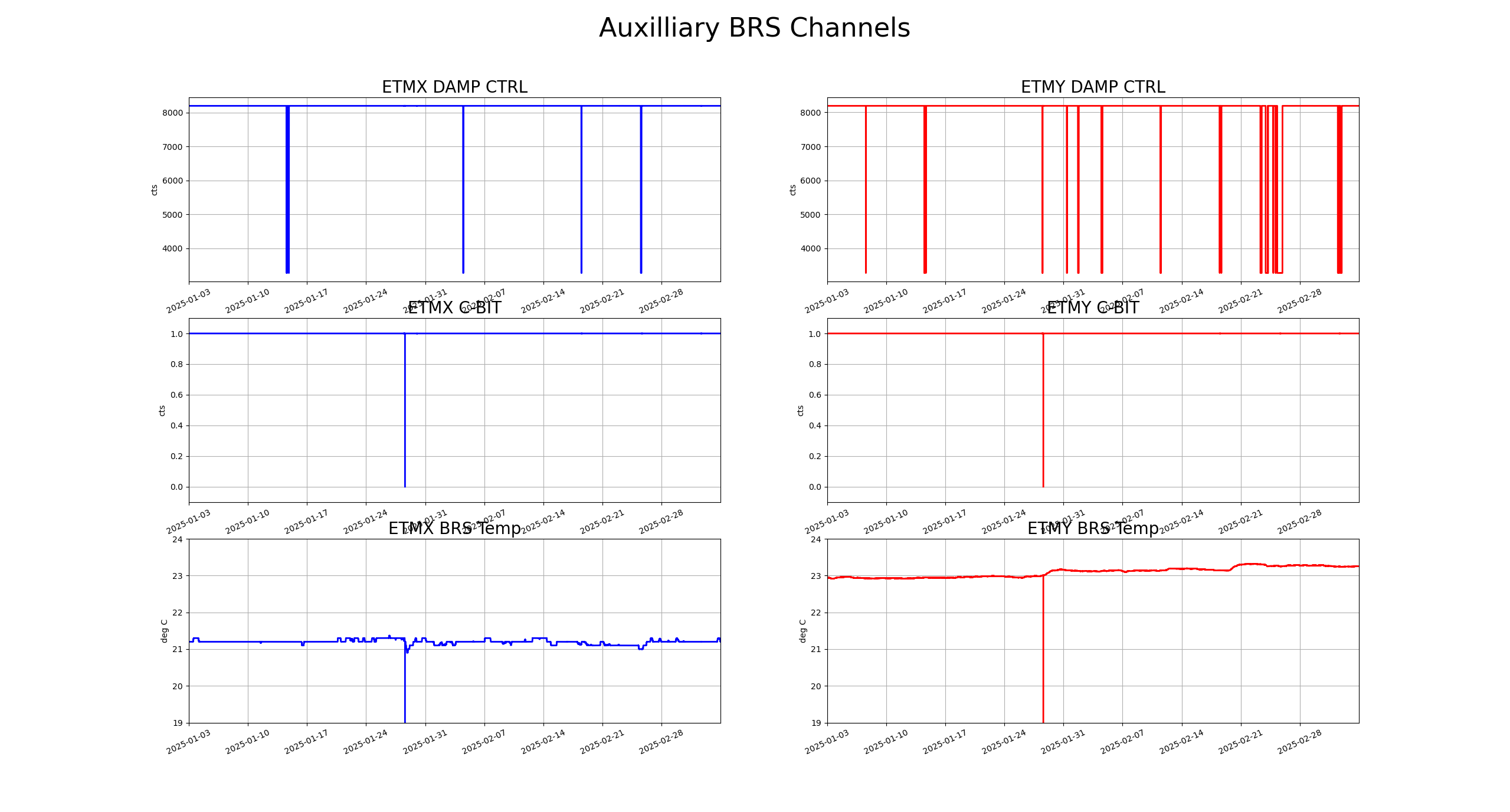
J. Kissel

I've been looking through the data captured about the PMC in the context of the two years of observatory use between July 2022 and July 2024 where we spanned a few "construction, commission, observe" cycles -- see LHO:83020. Remember the end goal is to answer the following question as quantitatively as possible: "does the PMC have a high enough duty cycle in the construction and commissioning phases that the SPI does *not* need to buy an independent laser?"

Conclusions: 
 - Since the marked change in duty cycle after the PMC lock-loss event on 2023-05-16, the duty-cycle of the PMC has been exceptionally high, either 91% during install/commissioning times or 99% during observing times. 
 - Most of the down time is from infrequent planned maintenance. 
 - Recovery time is *very* quick, unless the site loses power or hardware fails. 
 - The PMC does NOT lose lock when the IFO loses lock. 
 - The PMC does NOT lose lock just because we're vented and/or the IMC is unlocked. 
 - To-date, there are no plans to make any major changes to the PSL during the first one or two O4 to O5 breaks.
So, we shouldn't expect to lose the SPI seed light frequently, or even really at all, during the SPI install or during commissioning. And especially not during observing. 

This argues that we should NOT need an independent laser from an "will there even be light?" "won't IFO construction / commissioning mean that we'll be losing light all the time?"  duty-cycle stand point.
Only the pathfinder itself, when fully functional with the IFO, will tell us whether we need the independent laser from a "consistent noise performance" stand-point.

Data and Historical Review
To refresh your memory, the major milestones that happened between 2022 and 2024 (derived from a two year look through all aLOGs with the H1 PSL task):
- By Mar 2022, the PSL team had completed the complete table revamp to install the 2x NeoLase high-power amps, and addressed all the down-stream adaptations.

- 2022-07-01 (Fri): The data set study starts.
- 2022-09-06 (Tue): IO/ISC EOM mount updated, LHO:64882
- 2022-11-08 (Tue): Full IFO Commissioning Resumes after Sep 2022 to Dec 2022 vent to make FDS Filter Cavity Functional (see E2000005, "A+ FC By Week" tab)
- 2023-03-02 (Thu): NPRO fails, LHO:67721
- 2023-03-06 (Mon): NPRO and PSL function recovered LHO:67790
- 2023-04-11 (Tue): PSL Beckhoff Updates LHO:68586
- 2023-05-02 (Tue): ISS AOM realignment LHO:69259
- 2023-05-04 (Thu): ISS Second Loop Guardian fix LHO:69334
- 2023-05-09 (Tue): "Something weird happened to the PMC, then it fixed itself" LHO:69447
- 2023-05-16 (Tue): Marked change in PSL PMC duty-cycle, nothing specific PSL team did with the PMC, but the DC power supplies for the RF & ISC racks we replaced, 69631, while Jason tuned up the FSS path LHO:69637 
- 2023-05-24 : O4, and what we'll later call O4A, starts, we run with 75W requested power from the PSL.
- 2023-06-02 (Fri): PSL ISS AA chassis it was replaced, but PMC stays locked through it LHO:70089
- 2023-06-12 (Sun): PMC PDH Locking PD needs threshold adjustment, LHO:70352, for "never found out why" reason FRS:28260
- 2023-06-19 (Mon): PMC PDH Locking PD needs another threshold adjustment, LHO:70586, added to FRS:28260, but again reasons never found.
- 2023-06-21 (Wed): Decision made to reduce requested power into the IFO to 60W LHO:70648
- 2023-07-12 (Wed): Laser Interlock System maintenance kills PSL LHO:71273
- 2023-07-18 (Tue): Routine PMC / FSS tuneup, with quick PMC recovery LHO:71474
- 2023-08-06 (Sun): Site-wide power glitch takes down PSL LHO:72000
- 2023-09-22 (Fri): Site-wide power gltich takes down PSL LHO:73045
- 2023-10-17 (Tue): Routine PMC / FSS tuneup, with quick PMC recovery LHO:73513
- 2023-10-31 (Tue): Jeff does a mode scan sweeping the PMC FSR LHO:73905
- 2023-11-21 (Tue): Routine PMC / FSS tuneup, with quick PMC recovery LHO:74346
- 2024-01-16 : O4A stops, 3 months, focused on HAM567, no PSL work (see E2000005, "Mid-O4 Break 1" tab)
O4A to O4B break lock losses: 7
       2024-01-17 (Wed): Mid-vent, no IFO, no reported cause.
       2024-01-20 (Sat): Mid-vent, no IFO, no reported cause.
       2024-02-02 (Fri): Mid-vent, no IFO, no reported cause.
       2024-02-08 (Thu): Mid-vent, no IFO, no reported cause. During HAM6 close out, may be related to alarm system
       2024-02-27 (Tue): PSL FSS and PMC On-table Alignment LHO:76002.
       2024-02-29 (Thu): PSL Rotation Stage Calibration LHO:76046.
       2024-04-02 (Tue): PSL Beckhoff Upgrade LHO:76879.
- 2024-04-10 : O4 resumes as O4B start
O4B to 2024-07-01 lock losses: 1
       2024-05-28 (Tue): PSL PMC REFL tune-up LHO:78093.
- 2024-07-01 (Mon): The data set study ends.

- 2024-07-02 (Tue): The PMC was swapped just *after* this data set, LHO:78813, LHO:78814

By the numbers

Duty Cycle (uptime in days / total time in days)
     start_to_O4Astart: 0.8053
    O4Astart_to_O4Aend: 0.9450
    O4Aend_to_O4Bstart: 0.9181
       O4Bstart_to_end: 0.9954
(Uptime in days is the sum on the values of H1:PSL-PMC_RELOCK_DAY just before lock losses [boxed in red] in the attached trend for the given time period)

Lock Losses (number of times "days" goes to zero)
     start_to_O4Astart: 80
    O4Astart_to_O4Aend: 22
    O4Aend_to_O4Bstart: 7
       O4Bstart_to_end: 1
(Number of lock losses is mere the count of red boxes for the given time period)

Lock Losses per calendar days
     start_to_O4Astart: 0.2442
    O4Astart_to_O4Aend: 0.0928
    O4Aend_to_O4Bstart: 0.0824
       O4Bstart_to_end: 0.0123
(In an effort to normalize the locklosses over the duration of the time period to give a more fair assessment.)

I also attach a histogram of lock durations for each duration, as another way to look at how the duty cycle dramatically changed around the start of O4A.
Non-image files attached to this report
Comments related to this report
jeffrey.kissel@LIGO.ORG - 12:06, Saturday 08 March 2025 (83243)CDS, CSWG, SEI, SUS, SYS
The data used in the above aLOG was gathered by ndscope using the following template,
    /ligo/svncommon/SeiSVN/seismic/Common/SPI/Results/
        alssqzpowr_July2022toJul2024_trend.yaml


and then exported (by ndscope) to the following .mat file,
    /ligo/svncommon/SeiSVN/seismic/Common/SPI/Results/
        alssqzpowr_July2022toJul2024_trend.mat


and then processed with the following script to produce these plots
    /ligo/svncommon/SeiSVN/seismic/Common/SPI/Scripts/
        plotpmcuptime_20250224.m    rev 9866


ndscope have become quite an epically powerful data gathering tool!

H1 TCS (TCS)
ibrahim.abouelfettouh@LIGO.ORG - posted 14:29, Friday 07 March 2025 (83234)
TCS Monthly Trends - FAMIS 28458

Closes FAMIS 28458. Last checked in alog 82659.

Images attached to this report
H1 PSL (PSL)
corey.gray@LIGO.ORG - posted 11:49, Friday 07 March 2025 (83229)
PSL Status Report (FAMIS #26370)

This is for FAMIS #26370.
Laser Status:
    NPRO output power is 1.853W
    AMP1 output power is 70.51W
    AMP2 output power is 140.0W
    NPRO watchdog is GREEN
    AMP1 watchdog is GREEN
    AMP2 watchdog is GREEN
    PDWD watchdog is GREEN

PMC:
    It has been locked 30 days, 23 hr 28 minutes
    Reflected power = 22.36W
    Transmitted power = 106.5W
    PowerSum = 128.8W

FSS:
    It has been locked for 0 days 5 hr and 18 min
    TPD[V] = 0.7969V

ISS:
    The diffracted power is around 3.5%
    Last saturation event was 0 days 5 hours and 18 minutes ago

Possible Issues: None reported

H1 SEI (SEI)
corey.gray@LIGO.ORG - posted 11:42, Friday 07 March 2025 (83228)
SEI ground seismometer mass position check - Monthly (#26499)

Monthly FAMIS Check (#26499)

T240 Centering Script Output:

Averaging Mass Centering channels for 10 [sec] ...
2025-03-07 11:28:08.262570
There are 15 T240 proof masses out of range ( > 0.3 [V] )!
ETMX T240 2 DOF X/U = -0.975 [V]
ETMX T240 2 DOF Y/V = -1.02 [V]
ETMX T240 2 DOF Z/W = -0.554 [V]
ITMX T240 1 DOF X/U = -1.776 [V]
ITMX T240 1 DOF Y/V = 0.392 [V]
ITMX T240 1 DOF Z/W = 0.484 [V]
ITMX T240 3 DOF X/U = -1.843 [V]
ITMY T240 3 DOF X/U = -0.789 [V]
ITMY T240 3 DOF Z/W = -2.313 [V]
BS T240 1 DOF Y/V = -0.351 [V]
BS T240 3 DOF Y/V = -0.311 [V]
BS T240 3 DOF Z/W = -0.432 [V]
HAM8 1 DOF X/U = -0.317 [V]
HAM8 1 DOF Y/V = -0.434 [V]
HAM8 1 DOF Z/W = -0.712 [V]

All other proof masses are within range ( < 0.3 [V] ):
ETMX T240 1 DOF X/U = -0.006 [V]
ETMX T240 1 DOF Y/V = -0.014 [V]
ETMX T240 1 DOF Z/W = 0.009 [V]
ETMX T240 3 DOF X/U = 0.029 [V]
ETMX T240 3 DOF Y/V = -0.068 [V]
ETMX T240 3 DOF Z/W = -0.005 [V]
ETMY T240 1 DOF X/U = 0.082 [V]
ETMY T240 1 DOF Y/V = 0.171 [V]
ETMY T240 1 DOF Z/W = 0.24 [V]
ETMY T240 2 DOF X/U = -0.067 [V]
ETMY T240 2 DOF Y/V = 0.216 [V]
ETMY T240 2 DOF Z/W = 0.073 [V]
ETMY T240 3 DOF X/U = 0.26 [V]
ETMY T240 3 DOF Y/V = 0.114 [V]
ETMY T240 3 DOF Z/W = 0.146 [V]
ITMX T240 2 DOF X/U = 0.181 [V]
ITMX T240 2 DOF Y/V = 0.294 [V]
ITMX T240 2 DOF Z/W = 0.245 [V]
ITMX T240 3 DOF Y/V = 0.13 [V]
ITMX T240 3 DOF Z/W = 0.133 [V]
ITMY T240 1 DOF X/U = 0.082 [V]
ITMY T240 1 DOF Y/V = 0.123 [V]
ITMY T240 1 DOF Z/W = 0.04 [V]
ITMY T240 2 DOF X/U = 0.04 [V]
ITMY T240 2 DOF Y/V = 0.263 [V]
ITMY T240 2 DOF Z/W = 0.132 [V]
ITMY T240 3 DOF Y/V = 0.08 [V]
BS T240 1 DOF X/U = -0.161 [V]
BS T240 1 DOF Z/W = 0.156 [V]
BS T240 2 DOF X/U = -0.031 [V]
BS T240 2 DOF Y/V = 0.072 [V]
BS T240 2 DOF Z/W = -0.092 [V]
BS T240 3 DOF X/U = -0.139 [V]
Assessment complete.

STS Centering Script Output:

Averaging Mass Centering channels for 10 [sec] ...
2025-03-07 11:37:12.263138
There are 1 STS proof masses out of range ( > 2.0 [V] )!
STS EY DOF X/U = -2.334 [V]
All other proof masses are within range ( < 2.0 [V] ):
STS A DOF X/U = -0.503 [V]
STS A DOF Y/V = -0.757 [V]
STS A DOF Z/W = -0.603 [V]
STS B DOF X/U = 0.235 [V]
STS B DOF Y/V = 0.954 [V]
STS B DOF Z/W = -0.319 [V]
STS C DOF X/U = -0.862 [V]
STS C DOF Y/V = 0.801 [V]
STS C DOF Z/W = 0.681 [V]
STS EX DOF X/U = -0.041 [V]
STS EX DOF Y/V = -0.05 [V]
STS EX DOF Z/W = 0.102 [V]
STS EY DOF Y/V = -0.065 [V]
STS EY DOF Z/W = 1.318 [V]
STS FC DOF X/U = 0.195 [V]
STS FC DOF Y/V = -1.104 [V]
STS FC DOF Z/W = 0.659 [V]
Assessment complete.

LHO VE
david.barker@LIGO.ORG - posted 10:22, Friday 07 March 2025 (83226)
Fri CP1 Fill

Fri Mar 07 10:09:56 2025 INFO: Fill completed in 9min 52secs

Jordan confirmed a good fill curbside.

Images attached to this report
H1 SQZ (OpsInfo, SQZ)
corey.gray@LIGO.ORG - posted 09:45, Friday 07 March 2025 - last comment - 11:09, Friday 07 March 2025(83224)
SQZ SHG TEC Set Temperature Increased (+ opo_grTrans_setpoint lowered to 75)

SUMMARY:  Back To OBSERVING, but got here after going in a few circles.

H1 had a lockloss before the shift, but when I arrived H1 was at NLN, BUT SQZ had issues. 

I opened up the SQZ Overview screen and could see that the SQZ_SHG guardian node was bonkos (so I had this "all node" up the whole time...it was crazy because it was frantically moving through states to get LOCKED, but could not), BUT also I saw.....

1)  DIAG_MAIN

DIAG_MAIN had notifications flashing which said:  "ISS Pump is off. See alog 70050."  So, this is where I immediately switched focus.

2)  Alog70050:  "What To Do If The SQZ ISS Saturates"

Immediately followed the instructions from alog70050 which were pretty straightforward.  Remember:  H1's not Observing, so I jumped on the alog instructions and wanted to get back to Observing ASAP.)  I took the opo_grTrans_setpoint_uW from 80 to 50, and tried to get SQZ back to FDS, but no go (SQZ Manager stuck....and SQZ_SHG still bonkos!).

At this point, I saw that there were several other sub-entries with updated instructions and notes.  So I went through them and took opo_grTrans_setpoint_uW to 60 (no FDS + SQZ_SHG still crazy), and finally set opo_grTrans_setpoint_uW = 75 (but still no FDS + SQZ_SHG still crazy).

At this point, I'm assuming DIAG_SDF sent me on a wild goose chase.  Soooooo, I focused on the erratic SQZ_SHG......

3)  Alog search:  "SQZ_SHG"   --->   H1:SQZ-SHG_TEC_SETTEMP Taken to 33.9

This did the trick!  And this search took me to early Feb2025 alogs from (1) RyanS alog82599 which sounded what I had and then (2) Ibrahim's alog82581 which laid out instructions for what to do for adjusting the SHG TEC Set Temperature (went from 33.7 to 33.9; see attachment #1).  AND---during these adjustments the infamous SQZ_SHG finally LOCKED!!

After this it was easy and straightforward taking the SQZ Manager to FDS and get H1 back to Observing.

NOTE:  I wanted to see the last time this Set Temperature was adjusted and it was Feb 17, 2025.  Doing an alog search on just "SHG" + tag: SQZ took me to when it was last adjusted:  By ME!  During an OWL wake-up call, I adjusted this set point from ~35.1 to 33.7 on 02172025 at 1521utc/72amPST (see attachment #2).

The only SDF to ACCEPT was the H1:SQZ-SHG_TEC_SETTEMP  = 33.7 (see attachment #3).  BUT:  Remember other changes I made (when I erroneously thought I had to adjust the OPO TEC TEMP which are not in SDF:

Hindsight is 20/20, but if I addressed the "bonkos SQZ_SHG" via instructions from an alog search first, I would have saved some time!  :)

Images attached to this report
Comments related to this report
sheila.dwyer@LIGO.ORG - 11:09, Friday 07 March 2025 (83227)

During this time that the SHG guardian was cycling through it's states, that was happening because of the hard fault checker, which checks for errors on the SQZ laser, PMC transdiode, SHG demod, phase shifter.

The demod had an error because the RF level was too high, indeed this was above this threshold in this time and dropped back to normal allowing Corey to lock the squeezer.

The second screenshot shows a recent time that the SHG scaned and locked sucsesfully, in this case as the PZT scans the RF level goes up as expected when the cavity is close to resonance, and also goes above the threshold of 0dBm for a moment, causing the demod to have an error.  This must have happened not at the moment when the guardian was checking this error, so that the guardian allowed it to continue to lock.

It doesn't make sense to throw an error about this RF level when the cavity is scanning, so I've commented out the demod check from the hardfault checker. 

Also, looking at this hardfault checker, I noticed that it is check for a fault on the PMC trans PD.  It would be prefferable to have the OMC guardian do whatever checks it needs to do on the PMC, and trust the sqz manager to correctly not ask the SHG to lock when the PMC is unlocked.  Indeed, SQZ manager has a PMC checker when it is asking the SHG to lock, so I've commented out this PMC checker in the SHG guardian.  This same logic applies to the check on the squeezer laser, leaving us with only a check on the SHG phase shifter in the hardfault checker. 

Editing to add:  I wondered why Corey got the message about the pump ISS.  DIAG_MAIN has two checks for the squeezer, first that SQZ_MANAGER is in the nominal state, then second that the pump ISS is on.  I added an elif to the pump ISS one, so if the sqz manager isn't in the nominal state this will be the only message that the operator sees, Ryan Short and I looked at the SQZ_MANAGER and indeed it seems that there isn't a check for the pump ISS in FREQ_DEP_SQZ. 

SQZ_SHG guardian and DIAG_MAIN will need to be reloaded at the next oppurtunity.

Images attached to this comment
Non-image files attached to this comment
LHO General
corey.gray@LIGO.ORG - posted 07:46, Friday 07 March 2025 (83223)
Fri Ops Day Transition

TITLE: 03/07 Day Shift: 1530-0030 UTC (0730-1630 PST), all times posted in UTC
STATE of H1: Lock Acquisition
OUTGOING OPERATOR: Ryan S
CURRENT ENVIRONMENT:
    SEI_ENV state: CALM
    Wind: 4mph Gusts, 2mph 3min avg
    Primary useism: 0.02 μm/s
    Secondary useism: 0.22 μm/s
QUICK SUMMARY:

H1's just made it to NLN .after a 7.75hr lock overnight (lockloss), but has a SQZ ISS Pump Off issue.  microseism are low and winds are as well. 

H1 General (Lockloss)
anthony.sanchez@LIGO.ORG - posted 22:07, Thursday 06 March 2025 (83222)
Thursday Eve Shift Summary

TITLE: 03/07 Eve Shift: 0030-0600 UTC (1630-2200 PST), all times posted in UTC
STATE of H1: Lock Acquisition
INCOMING OPERATOR:  ->Ryan S.<-
CURRENT ENVIRONMENT:
    SEI_ENV state: CALM
    Wind: 14mph Gusts, 8mph 3min avg
    Primary useism: 0.03 μm/s
    Secondary useism: 0.20 μm/s
SHIFT SUMMARY:
H1 was locked for 7 Hours and 17 minutes.
Until a sudden and Unknown lockloss struck at 5:24 UTC, Screenshots of lockloss ndscopes attached.

I took the last half hour of my shift to run an Initial_alignment before the start of Ryans Shift.
H1 is currently just past at CARM_TO_TR.

LOG:                                                                                                                                                                                                                                                                                                                                                         

Start Time System Name Location Lazer_Haz Task Time End
00:32 WFS Keita Optics Lab Yes Parts for WFS 01:36


Images attached to this report
H1 SEI
anthony.sanchez@LIGO.ORG - posted 21:52, Thursday 06 March 2025 (83221)
BRS Drift Trends--Monthly

BRS Dift Trends --Monthly FAMIS 26452

BRSs are not trending beyond their red thresh holds.

Images attached to this report
H1 ISC (ISC)
keita.kawabe@LIGO.ORG - posted 18:26, Thursday 06 March 2025 - last comment - 16:33, Monday 10 March 2025(83220)
New in-vac POP WFS (HAM1) assembly is ready for testing

I assembled the 45MHz WFS unit in the optics lab. Assembly drawing: D1102002.

BOM:

I confirmed that the baseplate and the WFS  body are electrically isolated from each other.

There were many black spots on the WFS body (2nd pic) as well as the aluminum foil used for wrapping (3rd pic). It seems that this is a result of rubbing of aluminum against aluminum. I cannot wipe it off but this should be aluminum powder and not some organic material.

QPD orientation is such that the tab on the can is at 1:30 o'clock position seen from the  front (4th pic). You cannot tell it from the picture but there's a hole punched to the side of the can.

Clean SMP - dirty SMA cables are in a bag inside the other clean room in the optics lab. DB25 interface cable is being made (or was made?) by Fil.

Images attached to this report
Comments related to this report
corey.gray@LIGO.ORG - 12:28, Friday 07 March 2025 (83231)

This WFS Assembly (D1102002) has been given the dcc-generated Serial Number of:  S1300637 (with its electronics installed & sealed with 36MHz & 45MHz detection frequencies).  As Keita notes, this s/n is etched by hand on the WFS Body "part" (D1102004 s/n016).

Here is ICS information for this new POP WFS with the Assembly Load here:  ASSY-D1102002-S1300637

(NOTE:  When this WFS is installed in HAM1, we should also move this "ICS WFS Assy Load" into the next Assy Load up:  "ISC HAM1 Assembly" (ICS LINK:  ASSY-D1000313-H1)

daniel.sigg@LIGO.ORG - 16:33, Monday 10 March 2025 (83279)

Tested the in-vac POP_X sensor in the optics lab:

  1. Flashlight test: all 4 segments showed a DC response when a flashlight was pointed to the QPD.
  2. RF transfer functions from the test input to the individual segments; see attached plot. All traces look as expected.

All electronics tests passed! We are ready for installation.

Non-image files attached to this comment
H1 General
anthony.sanchez@LIGO.ORG - posted 16:41, Thursday 06 March 2025 (83219)
Thursday Eve Shift login

TITLE: 03/07 Eve Shift: 0030-0600 UTC (1630-2200 PST), all times posted in UTC
STATE of H1: Observing at 144Mpc
OUTGOING OPERATOR: TJ
CURRENT ENVIRONMENT:
    SEI_ENV state: CALM
    Wind: 21mph Gusts, 16mph 3min avg
    Primary useism: 0.06 μm/s
    Secondary useism: 0.25 μm/s
QUICK SUMMARY:

H1 has been locked and Observing for 2 hours and 23 minutes.
All systems are running well, though the range seems a bit low.

H1 General (DetChar)
oli.patane@LIGO.ORG - posted 16:38, Thursday 06 March 2025 (83218)
Ops Day Shift End

TITLE: 03/07 Day Shift: 1530-0030 UTC (0730-1630 PST), all times posted in UTC
STATE of H1: Observing at 146Mpc
INCOMING OPERATOR: Tony
SHIFT SUMMARY: Currently Observing at 147 Mpc and have been Locked for 2.5 hours. Relocking after the lockloss during the calibration measurements was fully automatic and went relatively smoothly.
LOG:

20:35UTC Lockloss during calibration measurements

22:07 NOMINAL_LOW_NOISE
22:10 Observing

23:25 Three military jet planes flew overhead at a very low altitude (tagging Detchar)                                                                                                                                                                                                                                

Start Time System Name Location Lazer_Haz Task Time End
16:02 FAC Nelly Opt lab n Tech clean 16:14
19:21 SQZ Sheila, Mayank LVEA - SQZ n SQZ rack meas. 19:52
21:05 TOUR Sheila, Nately LVEA N Tour 21:29
21:53 ISC Matt, Siva, Mayank OpticsLab n ISS Array Alignment 22:48
23:55 VAC Jordan, Fifer reps Mids n Vacuum work 00:39
00:32 WFS Keita Optics Lab Yes Parts for WFS 02:32
H1 DetChar (DetChar-Request)
elenna.capote@LIGO.ORG - posted 16:23, Thursday 06 March 2025 - last comment - 15:03, Friday 07 March 2025(83217)
Possible Scattered Light ~28 Hz

I found evidence of possible scattered light while looking at some data from a lock yesterday. Attached is a whitened spectrogram of 30 minutes of data starting at GPS 1425273749. It looks like the peaks are around 28, 38, and 48 Hz, but they are broad and it's hard to tell the exact frequency and spacing. Sheila thinks this may have appeared after Tuesday maintenance. Tagging detchar request so some tests can be run to help us track down the source!

Images attached to this report
Comments related to this report
sheila.dwyer@LIGO.ORG - 12:42, Friday 07 March 2025 (83232)

Ryan Short and I have been looking through the summary pages to see what we could learn about this. 

Our range has been shaggy and low since Tuesday, this does seem to line up well with Tuesday maintence. Comparing the glitch rate before and after Tuesday isn't as easy, Iara Ota pointed me to the DMT omega glitch pages to make the comparison for Wed when omicron wasn't working.  DMT omega pages don't show the problem very clearly, but the omicron based ones do show more glitches SNR 8 and higher since Tuesday maintence, we can compare Monday to Thursday

Hveto does flag something interesting, which is that the ETMX optical lever vetos a lot of these glitches, both the pitch and yaw channels are picked by hveto, and they don't seem related to glitches in other channels.  The oplev wasn't appearing in hveto before Tuesday. 

derek.davis@LIGO.ORG - 13:06, Friday 07 March 2025 (83233)DetChar

In recent weeks (every day after Feb 26), there have been large jumps in the amplitude of ground motion between 10-30 Hz at ETMX during the night. A good example of this behavior is on March 1 (see the relevant summary page plot from this page). This jump in ground motion occurs around 3 UTC and then returns to the lower level after 16 UTC. The exact times of the jumps change from night to night, but the change in seismic state is quite abrupt, and seems to line up roughly with the time periods when this scattering appears. 

Images attached to this comment
sheila.dwyer@LIGO.ORG - 15:03, Friday 07 March 2025 (83235)

Ryan found this alog from Oli: 83093 about this noise.  Looking back through the summary pages, it does seem that this started turning off and on Feb 20th, before the 20th this blrms was constantly at the level of 200 nm/s. 

Comparing the EX ground BLRMS to the optical lever spectra, whenever this ground noise is on you can see it in the optical lever pitch and yaw, indicating that the optical lever is sensing ground motion. Feb 22nd is a nice example of the optical lever getting quieter when the ground does.  However, at this time we don't see the glitches in DARM yet, and hveto doesn't pick up the optical lever channel until yesterday.  I'm having a hard time telling when this ground motion started to line up with glitches in DARM, it does for the last two days.

LHO FMCS
eric.otterman@LIGO.ORG - posted 14:50, Thursday 06 March 2025 (83215)
Mid station chilled water temperature trends
I ran each chilled water pump at the Mid Stations in order to exercise their seals and bearings since these pumps are currently off for the season. This will cause the temperature trending of the loop water to show an decrease for a brief period. The Mid Stations chillers are currently shut down and will remain off until late Spring. 
H1 SUS (SEI)
brian.lantz@LIGO.ORG - posted 16:23, Wednesday 05 March 2025 - last comment - 12:03, Monday 31 March 2025(83200)
cross-coupling and reciprocal plants

I'm looking again at the OSEM estimator we want to try on PR3 - see https://dcc.ligo.org/LIGO-G2402303 for description of that idea.

We want to make a yaw estimator, because that should be the easiest one for which we have a hope of seeing some difference (vertical is probably easier, but you can't measure it). One thing which makes this hard is that the cross coupling from L drive to Y readout is large.

But - a quick comparison (first figure) shows that the L to Y coupling (yellow) does not match the Y to L coupling (purple). If this were a drive from the OSEMs, then this should match. This is actuatually a drive from the ISI, so it is not actually reciprocal - but the ideas are still relevant. For an OSEM drive - we know that mechanical systems are reciprocal, so, to the extent that yellow doesn't match purple, this coupling can not be in the mechanics.

Never-the-less, the similarity of the Length to Length and the Length to Yaw indicates that there is likely a great deal of cross-coupling in the OSEM sensors. We see that the Y response shows a bunch of the L resonances (L to L is the red TF); you drive L, and you see L in the Y signal. This smells of a coupling where the Y sensors see L motion. This is quite plausible if the two L OSEMs on the top mass are not calibrated correctly - because they are very close together, even a small scale-factor error will result in pretty big Y response to L motion.

Next - I did a quick fit (figure 2). I took the Y<-L TF (yellow, measured back in LHO alog 80863) and fit the L<-L TF to it (red), and then subtracted the L<-L component. The fit coefficient which gives the smallest response at the 1.59 Hz peak is about -0.85 rad/meter. 

In figure 3, you can see the result in green, which is generally much better. The big peak at 1.59 Hz is much smaller, and the peak at 0.64 is reduced. There is more from the peak at 0.75 (this is related to pitch. Why should the Yaw osems see Pitch motion? maybe transverse motion of the little flags? I don't know, and it's going to be a headache).

The improved Y<-L (green) and the original L<-Y (purple) still don't match, even though they are much closer than the original yellow/purple pair. Hence there is more which could be gained by someone with more cleverness and time than I have right now.

figure 4 - I've plotted just the Y<-Y and Y<-L improved.

Note - The units are wrong - the drive units are all meters or radians not forces and torques, and we know, because of the d-offset in the mounting of the top wires from the suspoint to the top mass, that a L drive of the ISI has first order L and P forces and torques on the top mass. I still need to calculate how much pitch motion we expect to see in the yaw reponse for the mode at 0.75 Hz.

In the meantime - this argues that the yaw motion of PR3 could be reduced quite a bit with a simple update to the SUS large triple model, I suggest a matrix similar to the CPS align in the ISI. I happen to have the PR3 model open right now because I'm trying to add the OSEM estimator parts to it. Look for an ECR in a day or two...

This is run from the code {SUS_SVN}/HLTS/Common/MatlabTools/plotHLTS_ISI_dtttfs_M1_remove_xcouple'

-Brian


Images attached to this report
Comments related to this report
brian.lantz@LIGO.ORG - 11:27, Thursday 06 March 2025 (83209)

ah HA! There is already a SENSALIGN matrix in the model for the M1 OSEMs - this is a great place to implement corrections calculated in the Euler basis. No model changes are needed, thanks Jeff!

brian.lantz@LIGO.ORG - 15:10, Thursday 06 March 2025 (83216)

If this is a gain error in 1 of the L osems, how big is it? - about 15%.


Move the top mass, let osem #1 measure a distance m1, and osem #2 measure m2.

Give osem #2 a gain error, so it's response is really (1+e) of the true distance.
Translate the top mass by d1 with no rotation, and the two signals will be m1= d1 and m2=d1*(1+e)
L is (m1 + m2)/2 = d1/2 + d1*(1+e)/2 = d1*(1+e/2)
The angle will be (m1 - m2)/s where s is the separation between the osems.

I think that s=0.16 meters for top mass of HLTS (from make_sus_hlts_projections.m in the SUS SVN)
Angle measured is (d1 - d1(1+e))/s = -d1 * e /s

The angle/length for a length drive is
-(d1 * e /s)/ ( d1*(1+e/2)) = 1/s * (-e/(1+e/2)) = -0.85 in this measurement
if e is small, then e is approx = 0.85 * s = 0.85 rad/m * 0.16 m = 0.14

so a 14% gain difference between the rt and lf osems will give you about a 0.85 rad/ meter cross coupling. (actually closer to 15% -
0.15/ (1 + 0.075) = 0.1395, but the approx is pretty good.
15% seem like a lot to me, but that's what I'm seeing.

brian.lantz@LIGO.ORG - 09:54, Saturday 22 March 2025 (83489)

I'm adding another plot from the set to show vertical-roll coupling. 

fig 1 - Here, you see that the vertical to roll cross-couping is large. This is consistent with a miscalibrated vertical sensor causing common-mode vertical motion to appear as roll. Spoiler-alert - Edgard just predicted this to be true, and he thinks that sensor T1 is off by about 15%. He also thinks the right sensor is 15% smaller than the left.

-update-

fig 2- I've also added the Vertical-Pitch plot. Here again we see significant response of the vertical motion in the Pitch DOF. We can compare this with what Edgard finds. This will be a smaller difference becasue the the pitch sensors (T2 and T3, I think) are very close together (9 cm total separation, see below).

Here are the spacings as documented i the SUS_SVN/HLTS/Common/MatlabTools/make_sushlts_projections.m

% These distances are defined as magnet-to-magnet, not magnet-to-COM
M1.RollArm = 0.140; % [m]
M1.PitchArm = 0.090; % [m]
M1.YawArm = 0.160; % [m]
Images attached to this comment
edgard.bonilla@LIGO.ORG - 18:10, Monday 24 March 2025 (83539)

I was looking at the M1 ---> M1 transfer functions last week to see if I could do some OSEM gain calibration.

The details of the proposed sensor rejiggling is a bit involved, but the basic idea is that the part of the M1-to-M1 transfer function coming from the mechanical plant should be reciprocal (up to the impedances of the ISI). I tried to symmetrize the measured plant by changing the gains of the OSEMs, then later by including the possibility that the OSEMs might be seeing off-axis motion.

Three figures and three findings below:

0)  Finding 1: The reciprocity only allows us to find the relative calibrations of the OSEMs, so all of the results below are scaled to the units where the scale of the T1 OSEM is 1. If we want absolute calibrations, we will have to use an independent measurement, like the ISI-->M1 transfer functions. This will be important when we analyze the results below.

1) Figure 1:  shows the full 6x6 M1-->M1 transfer function matrix between all of the DOFs in the Euler basis of PR3. The rows represent the output DOF and the columns represent thr input DOF. The dashed lines represent the transpose of the transfer function in question for easier comparison. The transfer matrix is not reciprocal.

2) Finding 2: The diagonal correction (relative to T1) is given by:

            T1         T2          T3          LF          RT         SD
            1            0            0            0            0            0      T1
            0         0.89          0            0            0            0      T2
            0            0         0.84          0            0            0      T3
            0            0            0         0.86          0            0      LF
            0            0            0            0            1            0      RT
            0            0            0            0            0         0.84    SD
 
This shows the 14% difference between RT and LF that Brian saw (leading to L-Y coupling in the ISI-to-M1 transfer functions)
This also shows the 10-16% difference between T2/T3 and T1 that leads to the V-R coupling that  Brian posted in the comment above.
Since we normalized by T1, the most likely explanation for the discrepancies is that T1 and RT are both 14% ish low compared to the other 4 sensors. 
 
3) Figure 2:  shows the 6x6 M1-->M1 transfer function matrix, after applying the scaling factors.
The main difference is in the Length-to-Yaw and the Vertical-to-Roll degrees of freedom, as mentioned before. Note that the rescaling was made only to make the responses more symmetric, the decoupling of the dofs a welcome bonus.
 
4) Finding 3: We can go one step further and allow the sensors to be sensitive to other directions. In this case, the matrix below is mathematically moving the sensors to where the actuators are, in an attempt to collocate them as much as possible.
            T1            T2            T3              LF             RT             SD
                1         0.03         0.03        -0.001       -0.006        0.038      T1
        0.085        0.807        0.042       0.005        0.006        0.006      T2
        0.096        0.077        0.723       0.013        0.002         0.03       T3
       -0.036        0.025        -0.02        0.696        0.012        0.006      LF
       -0.004       -0.018        0.045       0.016        0.809       -0.004     RT
       -0.035        0.026         0.02        0.004       -0.008        0.815      SD
I haven't yet found a good interpretation for these numbers, beyond the idea that they mean the sensors and actuators are not collocated.
Three reasons come to mind:
a) The flags and the magnets are a bit off from each other and we are able to pick it up the difference.
b) The OSEMs are sensing sideways motion of the flag.
c) The actuators are pushing (or torquing) the suspension in other ways than their intended direction.
 
The interesting observation comes when observing Figure 3 .
After we apply this correction to the sensor side of the transfer function, we see a dramatic change in the symmetry and the amplitude of the transfer matrix. Particularly, the Transverse degree of freedom is much less coupled to both Vertical and Longitudinal. Similarly, the Pitch to Vertical also improves a bit.
This is to say, by trying to make the plant more reciprocal, we also end up decoupling the degrees of freedom. We can conclude that there's either miscollocation of the sensor/actuator parts of the OSEM, or, more likely, that the OSEMs are reading side motions of the flag, because we are able to better see the decoupled plant by just assuming this miscalibration.

I will post more analysis in the Euler basis later.

Non-image files attached to this comment
brian.lantz@LIGO.ORG - 15:06, Tuesday 25 March 2025 (83555)

Here's a view of the Plant model for the HLTS - damping off, motion of M1. These are for reference as we look at which cross-coupling should exist. (spoiler - not many)

First plot is the TF from the ISI to the M1 osems.
L is coupled to P, T & R are coupled, but that's all the coupling we have in the HLTS model for ISI -> M1.

Second plot is the TF from the M1 drives to the M1 osems.
L & P are coupled, T & R are coupled, but that's all the coupling we have in the HLTS model for M1 -> M1.

These plots are Magnitude only, and I've fixed the axes.

For the OSEM to OSEM TFs, the level of the TFs in the blank panels is very small - likely numerical issues. The peaks are at the 1e-12 to 1e-14 level.

Images attached to this comment
Non-image files attached to this comment
jeffrey.kissel@LIGO.ORG - 12:03, Monday 31 March 2025 (83662)CSWG, SUS
@Brian, Edgard -- I wonder if some of this ~10-20% mismatch in OSEM calibration is that we approximate the D0901284-v4 sat amp whitening stage with a compensating filter of z:p = (10:0.4) Hz?
(I got on this idea thru modeling the *improvement* to the whitening stage that is already in play at LLO and will be incoming into LHO this summer; E2400330)

If you math out the frequency response from the circuit diagram and component values, the response is defined by 
    %  Vo                         R180
    % ---- = (-1) * --------------------------------
    %  Vi           Z_{in}^{upper} || Z_{in}^{lower}
    %
    %               R181   (1 + s * (R180 + R182) * C_total)
    %      = (-1) * ---- * --------------------------------
    %               R182      (1 + s * (R180) * C_total)
So for the D0901284-v4 values of 
    R180 = 750;
    R182 = 20e3;
    C150 = 10e-6;
    C151 = 10e-6;

    R181 = 20e3;

that creates a frequency response of 
    f.zero = 1/(2*pi*(R180+R182)*C_total) = 0.3835 [Hz]; 
    f.pole = 1/(2*pi*R180*C_total) = 10.6103 [Hz];


I attach a plot that shows the ratio of the this "circuit component value ideal" response to approximate response, and the response ratio hits 7.5% by 10 Hz and ~11% by 100 Hz.

This is, of course for one OSEM channel's signal chain. 

I haven't modeled how this systematic error in compensation would stack up with linear combinations of slight variants of this response given component value precision/accuracy, but ...

... I also am quite confident that no one really wants to go through an measure and fit the zero and pole of every OSEM channel's sat amp frequency response, so maybe you're doing the right thing by "just" measuring it with this technique and compensating for it in the SENSALIGN matrix. Or at least measure one sat amp box's worth, and see how consistent the four channels are and whether they're closer to 0.4:10 Hz or 0.3835:10.6103 Hz.

Anyways -- I thought it might be useful to be aware of the many steps along the way that we've been lazy about the details in calibrating the OSEMs, and this would be one way to "fix it in hardware."
Non-image files attached to this comment
Displaying reports 2521-2540 of 83355.Go to page Start 123 124 125 126 127 128 129 130 131 End