Ibrahim, Betsy, Anamaria
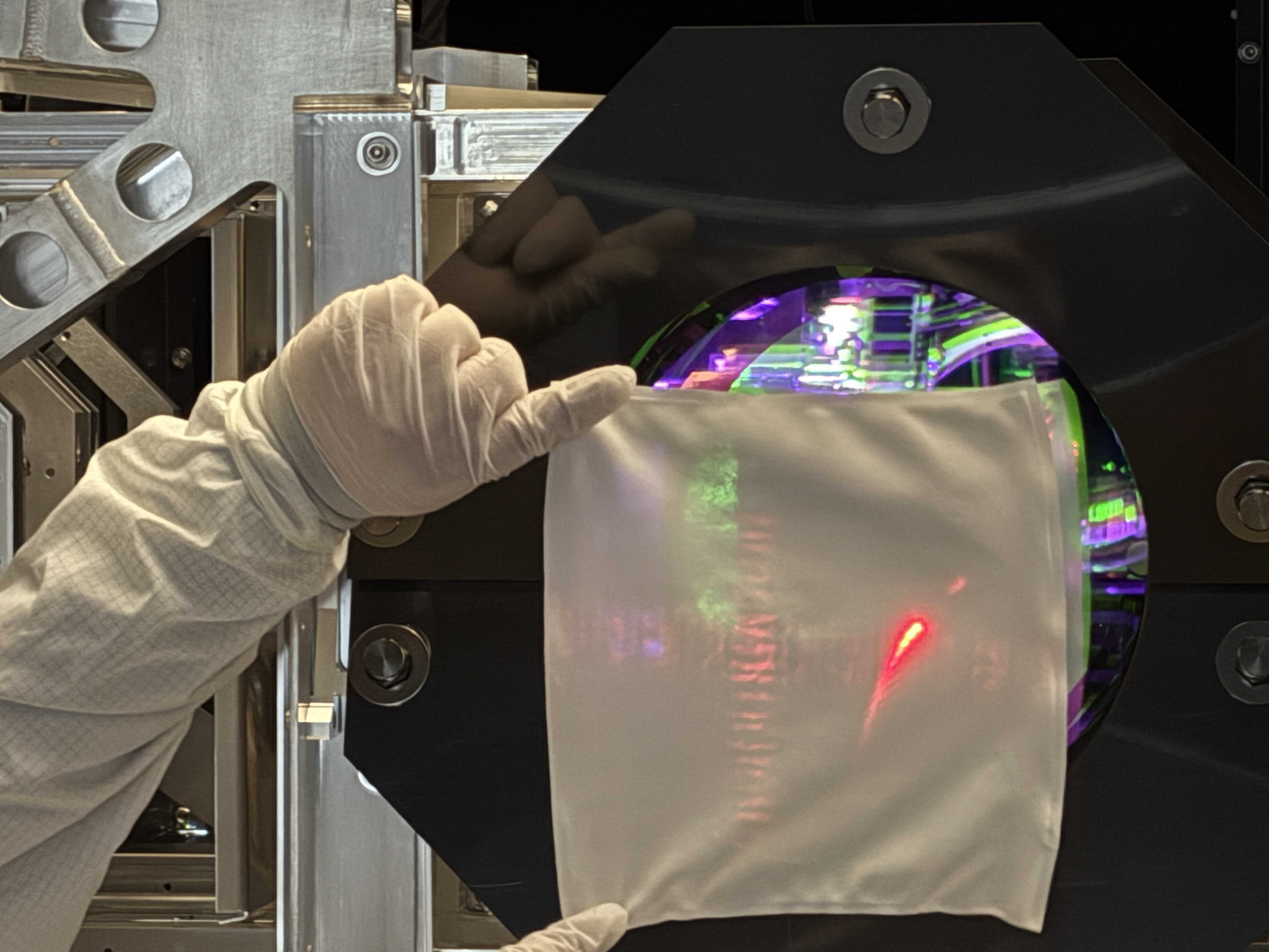
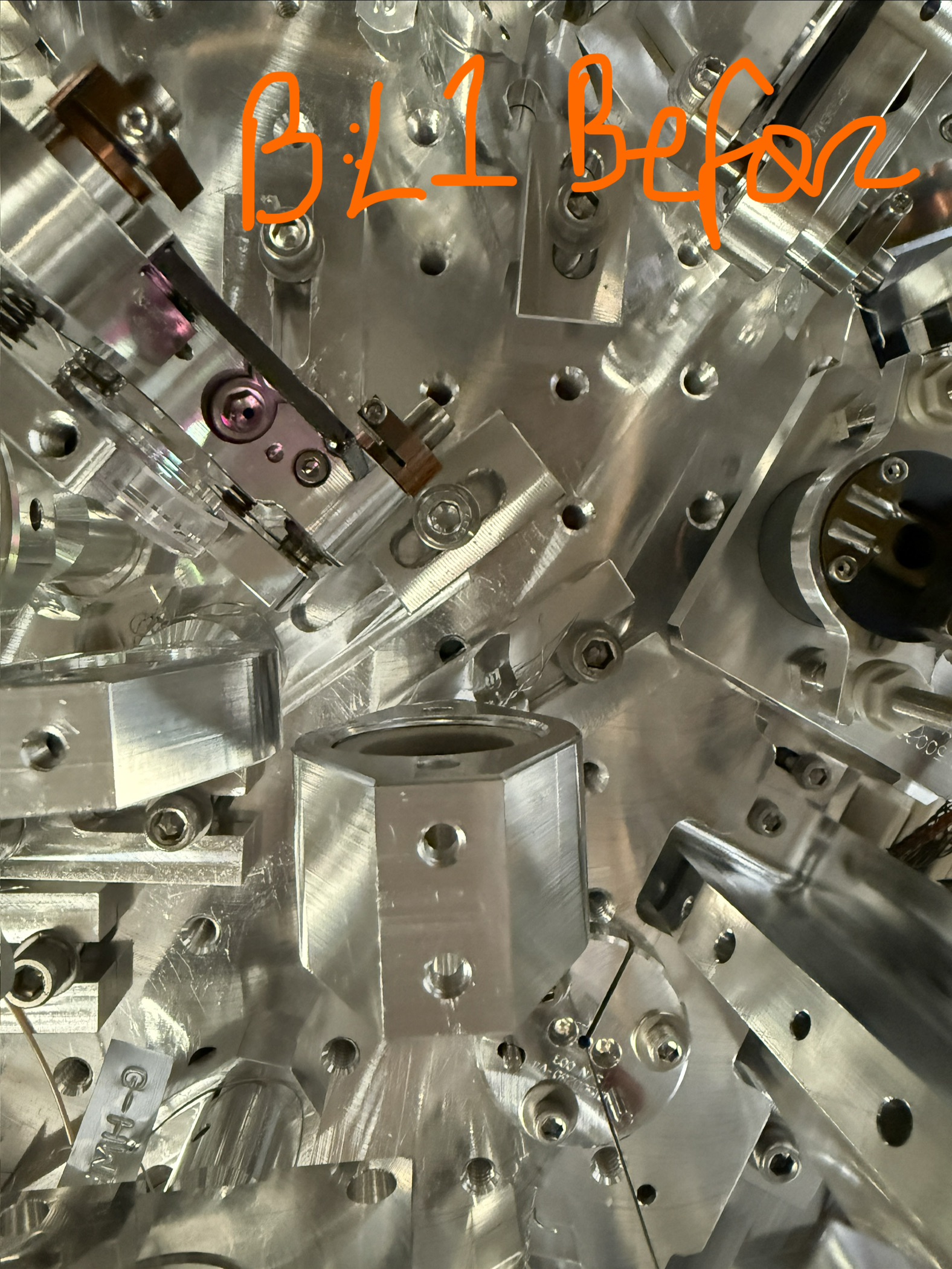
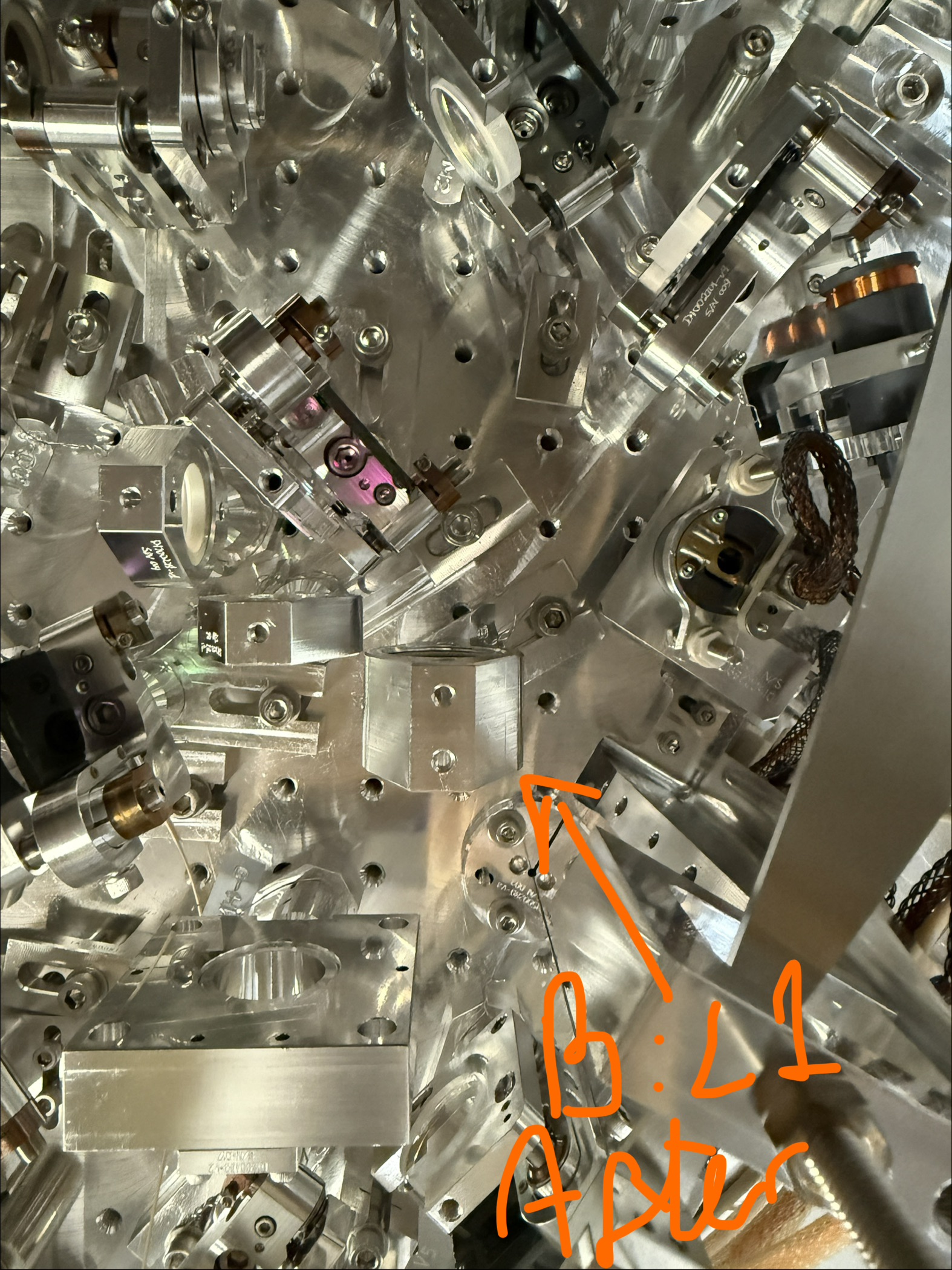
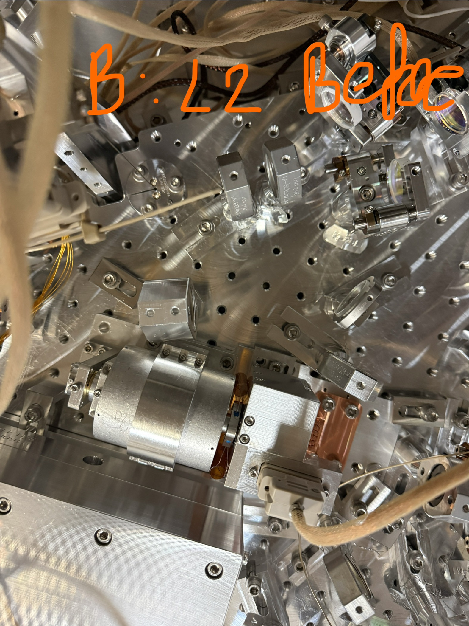
Upon first in-chamber BBS01 inspection, we found 3 large clumps of spots approximately 100mm from the edge. We're consulting GariLynn at CIT for steps on how to clean.
Acetone swab: We tried to go over the spots with a cotton swab with acetone, but the spots remained.
First contact: We then tried to first contact a small portion with one thin layer, but the spots remained.
While there's no evidence that the beamsplitter was contacted, dinked, touched or scratched in anyway, this might be a cause for the damage. There is texture to the spots upon brushing them with a swab and while it seems more likely that these are above the surface, we are not totally sure.
Hypotheses (and their problems)
1. Peek In-Vac cable scratch: maybe an in-vac cable fell on that area but they would have had to imprint multiple times with some force to show something like this.
2. Falling foil: maybe a piece of foil fell onto the surface and scratched it that way? No foil was used or wrapped at height during BBS and again, the foil would have had to fall with some heft.
3. There-the-whole-time: Maybe the spots were there the whole time and are invisible to non-chamber conditions. Because this is on the AR side, there is no good scatter plot of the surface. Since we did not see this in normal light conditions, but immediately saw this in chamber (dark) conditions, this may have been there all along. The spots are quite large (as attachments show), so this makes that less likely.
4. Dry first contact: Maybe it's dry first contact? We went over some of the spot with acetone but it stayed. We also first contacted a thin layer on one part but it stayed. The nature of the spots do look like they're small first contact bubbles. We found the first contact sheet that we used on that side and indeed, there are some similar streaks in size but nothing conclusive. We're looking at matching the spot with the first contact to see if there is a streak in this region. Problem is - first contact wouldve come off quick with the acetone treatment. So this is also not likely it.
What to do next:
- Analyze with Dino-Lite: We're going to zoom in on the spots with our DinoLite mount to get a better look. This could tell us if they are truly scratches or stuck particulate.
- Match first contact sheet with spots: Seeing if these spots were visible during FC (done on May 6) - alog 90149. Nothing visible.
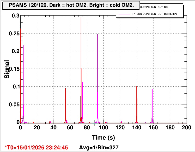
- Anamaria suggested at any rate shining a gaussian beam at it to analyze the damage in a short experiment to characterize.
Ibrahim, Betsy
First, we imaged the spot, which yeilded these attached pictures of what look like... specks. No idea what these may be.
We then went over the spot with some thicker first contact, which did not remove any of the specks.
We recieved the procedure for spot-water cleaning which is the only last thing that we're thinking of trying.
In the attachment, the thinner lines are dry acetone and can be removed. Focus on the brighter dots instead.
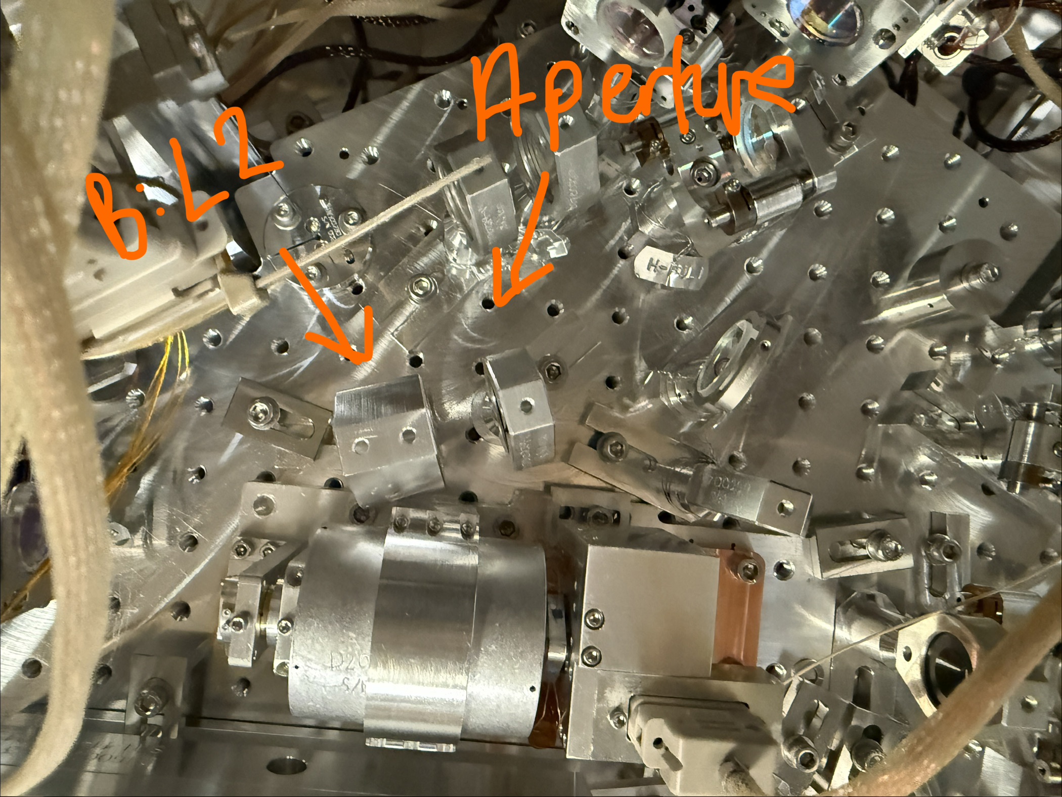
Also adding a "map" of our AR side features thus far. I will digitize it and add this as an alog/DCC of its own once we're done with optic inspection.
TITLE: 06/11 Day Shift: 1430-2330 UTC (0730-1630 PST), all times posted in UTC
STATE of H1: Planned Engineering
INCOMING OPERATOR: None
SHIFT SUMMARY:
More Fist contacting the Beam Splitter was done along with Top Gunning it as well.
The SEI HEPI Team of 5 has been trying to Align HEPI.
HAM2 SUS TF were taken.
Viewports inspected by the VAC team.
Jim Is currently taking TFs before floating the ISI in HAM2.
Dave swapped out a timing card WP 13324.
Fast shutter is now working again, Confirmed by Sheila and Camilla.
GRB_Short E640741 @ 21:33:37 UTC
GRB_Short E640743 @ 21:43:41 UTC
LOG:
| Start Time | System | Name | Location | Lazer_Haz | Task | Time End |
|---|---|---|---|---|---|---|
| 22:52 | SAF | LVEA is Laser SAFE | LVEA | NO | LVEA is Laser SAFE | 16:52 |
| 14:48 | FAC | Kim | LVEA | N | Technical cleaning and Resupply | 16:34 |
| 14:58 | BSC2 | Betsy | LVEA | N | Collecting parts, and taking in chamber BSC2 Pics. | 16:07 |
| 15:01 | SUS | Rahul | Remote. | N | taking MC1 - MC3 \\ transfer functions | 16:35 |
| 15:04 | FAC | Randy | LVEA HAM3 | N | MOvign the Nitrogen bottle to HAM3 so folks can top gun | 15:40 |
| 15:33 | EE | Fil | LVEA | N | Placing Bypass on HAM6 High voltage WP #13322 | 15:49 |
| 15:52 | VAC | Gerardo | LVEA | N | Checking HAM2 area and west bay | 16:13 |
| 16:08 | SEI | Jim, Ryan C, Jason | LVEA | N | Working on HEPI Alignment | 17:01 |
| 16:13 | SUS | Ibrahim & Betsy | LVEA | N | Playing with BS smudge looking thing | 17:00 |
| 16:14 | PEM | Anamaria | LVEA | N | Joing the BSC2 smudging crew | 17:00 |
| 16:17 | SQZ | Camilla | LVE SQZ bay | y | Helping Kim put up the Laser Bifurcation fence. | 16:22 |
| 16:26 | FAC | Mitchel | LVEA | N | Getting parts and inventory and staging for helping Jim | 16:50 |
| 16:31 | SEI | Randy | LVEA | N | Helping Jim with HEPI actuation | 16:52 |
| 16:33 | VAC | Travis | LVEA | n | getting part numbers off of pump carts. | 16:40 |
| 16:38 | CRS | Oli, Alex, S. Apple | Optics lab, H2 PSL | local | Looking for top gun and cleaning optics in Laser haz | 19:17 |
| 16:46 | FAC | Kim and Dawn | LVEA | N | Technical cleaning and resupply | 17:36 |
| 17:42 | SQZ | Camilla & Sheila | LVEA HAM6 | Local | Tetsing the fast shuter. | 18:07 |
| 19:00 | PEM | Ryan C | LVEA HAM6 | Local | Checking the Dust mon | 19:09 |
| 19:05 | VAC | Camilla | LVEA HAM6 | Local | Turning Purge air down. | 19:17 |
| 19:27 | VAC | Travis | Mid Y | N | Cheking Pipe cutter fitment. | 20:21 |
| 19:38 | BCS2 | AnnaMaria & Betsy & Ibrihim | LVEA | N | Inspecting BSC2 from the inside, maybe top gunnin? Annamaria Out First | 21:20 |
| 20:04 | VAC | Keita, Jordan, Gerardo | LVEA HAM2 | N | Veiwport checks, jordan out first | 21:15 |
| 20:18 | IAS | Ryan C & Jason | LVEA | N | Prepping Faro Ryan out First | 23:08 |
| 20:21 | SEI | Jim | LVEA | N | HEPI Alignment. | 23:21 |
| 20:40 | CDS | Patrick | MSR | n | Reimaging CS power monitoring Beckoff | 22:26 |
| 20:57 | CRS | Shoshana | LVEA H2 PSL | LOCAL | Dropping off parts tools and Assembly | 22:24 |
| 21:10 | Tour | Landry & Jennie D & Co | Overpass | n | Giving a Tour | 22:40 |
| 21:16 | VAC | Jordan & Gerardo | Mids | N | Looking for parts | 22:26 |
| 21:17 | SEI | Mitchell | LVEA | N | BSC2 HEPI Alignment work with Jim | 22:34 |
| 21:18 | CDS | Dave | HAM SHAQ | N | DAQ restarts and replace the timing card | 22:43 |
| 22:56 | CDS | Dave | HAM Shaq | N | Troubleshooting unresponsive DAQ issues. | 00:56 |
We visually inspected the windows on the HAM1-HAM2 septum and wiped the bottom of the cylindrical window recess. I found nothing that might be a structural risk.
IFO REFL window (bottom +Y) had two big particulates as well as tiny ones. Gerardo blew off the big ones using an empty iso-propanohl squirt bottle as an air puffer. After that he wiped the recess for the window and picked up something, which we guess is one of the big particulates that were removed from the window. Tinier particulates stayed. There was also about half to 3/4-inch long line close to the top of the window. It might be surface scratch, didn't move, and might have been there for a long time. Since it's 1/4" or so from the edge of the optic and very far from where the beam will hit I say this is OK.
Main PSL beam window (top middle) had tiny particulates but no big ones. These were not moving when Jordan tried to blow them off. I say these are fine.
POP/ALS window (top +Y) as well as unused window (bottom -Y)looked fine.
WP 13326
Dave noted we lost Beckhoff channels yesterday around 6PM. Daniel logged in and confirmed terminals missing in Corner Chassis 4. The third EtherCAT coupler was replaced.
Chassis Serial Number S1107450
D. Barker, F. Clara, D. Sigg
Attached are pictures of where the CO2 alignment lasers are hitting near the CPs. Neither look well centered, but it's tough to say since the cloth is held a bit away from the CP and is coming in at an angle. We also don't know where these alignment lasers were hitting before the vent. The TCSX alignment laser was going nicely through the iris, but for TCSY I had bumped one iris during the water line swap (alog90234) bumping it down.
Both alignment lasers look to be hitting the optic, so I think at this point we will just plan to use the HWS to make any moves with the CO2 once we are closed up and pumped down.
In the two attached pictures, the bright spot is the oplev, the alignment laser is the faint cross pattern.
I finally got around to doing some slight alignment tweaks this morning following the power outage and PSL recovery a bit over a week ago.
I started with the remotely-controlled picomotors upstream of the PMC to touch up its input alignment with the ISS off:
Some improvement here, but I couldn't quite get the transmitted power back up to the >104 W level it was before the outage. Perhaps amplifier pump diode currents need to be adjusted, or some more invasive alignment tweaks are needed. I then turned the ISS on and adjusted the RefSignal to bring the diffracted power percentage back up to 4% from around 3%, and proceeded with RefCav adjustments:
Again, good improvements, but the highest I've seen this signal get in recent memory is around 550 mV, so the FSS path may need a full tune-up sometime. Not completely surprising, as it's been a while since the last one.
Attaching a screenshot of the quad display after my adjustments for posterity.
Camilla Sheila
Pre door close suspension transfer function health check (taken while ISI was locked) measurements looks good. Oli Took IM1-4 (LHO alog 90579) and they look healthy as well.
I will process and post the results later on, the templates are stored at the following location (given below).
/ligo/svncommon/SusSVN/sus/trunk/HSTS/H1/MC1/SAGM1/Data
2026-06-11_1600_H1SUSMC1_M1_WhiteNoise_L_0p02to50Hz.xml
2026-06-11_1600_H1SUSMC1_M1_WhiteNoise_P_0p02to50Hz.xml
2026-06-11_1600_H1SUSMC1_M1_WhiteNoise_R_0p02to50Hz.xml
2026-06-11_1600_H1SUSMC1_M1_WhiteNoise_T_0p02to50Hz.xml
2026-06-11_1600_H1SUSMC1_M1_WhiteNoise_V_0p02to50Hz.xml
2026-06-11_1600_H1SUSMC1_M1_WhiteNoise_Y_0p02to50Hz.xml
/ligo/svncommon/SusSVN/sus/trunk/HSTS/H1/MC3/SAGM1/Data
2026-06-11_1630_H1SUSMC3_M1_WhiteNoise_L_0p02to50Hz.xml
2026-06-11_1630_H1SUSMC3_M1_WhiteNoise_P_0p02to50Hz.xml
2026-06-11_1630_H1SUSMC3_M1_WhiteNoise_R_0p02to50Hz.xml
2026-06-11_1630_H1SUSMC3_M1_WhiteNoise_T_0p02to50Hz.xml
2026-06-11_1630_H1SUSMC3_M1_WhiteNoise_V_0p02to50Hz.xml
2026-06-11_1630_H1SUSMC3_M1_WhiteNoise_Y_0p02to50Hz.xml
/ligo/svncommon/SusSVN/sus/trunk/HSTS/H1/PRM/SAGM1/Data
2026-06-11_1700_H1SUSPRM_M1_WhiteNoise_L_0p01to50Hz.xml
2026-06-11_1700_H1SUSPRM_M1_WhiteNoise_P_0p01to50Hz.xml
2026-06-11_1700_H1SUSPRM_M1_WhiteNoise_R_0p01to50Hz.xml
2026-06-11_1700_H1SUSPRM_M1_WhiteNoise_T_0p01to50Hz.xml
2026-06-11_1700_H1SUSPRM_M1_WhiteNoise_V_0p01to50Hz.xml
2026-06-11_1700_H1SUSPRM_M1_WhiteNoise_Y_0p01to50Hz.xml
/ligo/svncommon/SusSVN/sus/trunk/HLTS/H1/PR3/SAGM1/Data
2026-06-11_1800_H1SUSPR3_M1_WhiteNoise_L_0p02to50Hz.xml
2026-06-11_1800_H1SUSPR3_M1_WhiteNoise_P_0p02to50Hz.xml
2026-06-11_1800_H1SUSPR3_M1_WhiteNoise_R_0p02to50Hz.xml
2026-06-11_1800_H1SUSPR3_M1_WhiteNoise_T_0p02to50Hz.xml
2026-06-11_1800_H1SUSPR3_M1_WhiteNoise_V_0p02to50Hz.xml
2026-06-11_1800_H1SUSPR3_M1_WhiteNoise_Y_0p02to50Hz.xml
WP13322. This morning Fil set up the HAM6 High-Voltage Bypass from the CER and then verified that the fast shutter was charged and energized.
This is for SQZ work, when sending the SQZ beam towards HAM5/6 into the OMC, we need high voltage supplied to the fast shutter and OMC PZT in HAM6.
Ibrahim, Oli
Yesterday afternoon the BS was unlocked in chamber and Ibrahim took transfer functions. They look great and everything looks like it did in the test stand.
Settings
- HEPI Locked
- ISI Locked
- DAMP OFF
- OPTICALIGN sliders OFF
Data
/ligo/svncommon/SusSVN/sus/trunk/BBSS/H1/BS/SAGM1/Data/2026-06-10_1700_tfs/2026-06-10_1700_H1SUSBS_M1_WhiteNoise_{L,T,V,R,P,Y}_0p02to50Hz.xml
Results
/ligo/svncommon/SusSVN/sus/trunk/BBSS/H1/BS/SAGM1/Results/2026-06-10_1700_tfs/2026-06-10_1700_tfs/2026-06-10_1700_H1SUSBS_M1_ALL_TFs.pdf
r13035
TITLE: 06/11 Day Shift: 1430-2330 UTC (0730-1630 PST), all times posted in UTC
STATE of H1: Planned Engineering
OUTGOING OPERATOR: None
CURRENT ENVIRONMENT:
SEI_ENV state: MAINTENANCE
Wind: 3mph Gusts, 1mph 3min avg
Primary useism: 0.02 μm/s
Secondary useism: 0.10 μm/s
QUICK SUMMARY:
Expected work today:
SPI crew is out, and laser safe.
More BSC2 HEPI actuator work.
Final ISI unlock perhaps?
CRS Chamber side testing?
BSC2 & HAM3 in chamber work
TCS HeNe alignment check in BSC1&3
Crane CRS+ table to HAM3
CRS cable runs.
BBSS model up ?
WP13311 Check 20it-DACs
Summary of work done as part of the 20bit-DAC issue discovered last week by Sheila when driving FC1 in HAM7. Not all channels of the first 20bit-DAC have been driving since the 13apr2026 upgrade of h1sush7 timing-card firmware, TC-sync-ribbon and RCG5.5.0 to RCG5.5.2.
We have 4 more frontends with 20bit-DACs in the same configuration as h1sush7, they are: h1susb2h34, h1cdsh8, h1oaf0 and h1iscex.
We have been unable to reproduce this issue on the test stand (x7eetest1).
On Tuesday 09jun2026 we investigated the status of h1oaf0's 20bit-DAC and on Wednesday 10jun2026 h1iscex.
-----
h1oaf0: Tue 09jun2026.
The first 20bit-DAC has all 8 channels driven by the h1pemcs model. We used this model to drive the DAC for our tests. This DAC has a "CAL" Anti-Image chassis, each channel has a single ended BNC and a DB9 differential output.
We labeled and disconnected the field cables from the AI for ch0,1,2,3,4,6 (BNC) and ch7 (DB9). Ch5 was not being used.
We drove all 8 channels to 5.0V (262144 counts) and DVM'ed all the channels, no drive on any channel. Note this differs from h1sush7's test Tue02apr2026 where its ch7 DAC-DUOTONE was working but the others were not.
This gave us the opportunity to carefully test each change made on 13apr2026 to narrow down which change caused the issue.
Replace 20bit-DAC: First we replaced h1oaf0's DAC (S2101135) with the one tested on x7eetest1 (S2101117). BROKEN.
Install original Sync Ribbon Cable: replaced the upgraded sync ribbon (with the 2 wire shift) with the original pin-for-pin cable. BROKEN
Install new Sync Ribbon Cable backwards: we put the new ribbon back in, but connected it backwards. BROKEN
No Sync Ribbon Cable: ran with no ribbon cable. BROKEN.
we put the new ribbon back in correctly. Problem does not appear to be related to this cable in any way.
Shift all Cards Left: We then applied the "h1sush7 fix" which is to move all the cards left one slot, moving the 20bit-DAC from A1-4 to A2-1 in the process. NOW WORKING.
Move 20bit-DAC back: With all the other cards still moved left, we returned the 20bit-DAC back to its original slot (A2-1 to A1-4). BROKEN
Downgrade RCG: Erik downgraded all of h1oaf0's models from RCG5.5.2 to RCG5.5.0. BROKEN
Shuffle cards on Adnaco A1: Next the order of the cards on A1 was shuffled
From
| A1-4 | A1-3 | A1-2 | A1-1 |
| 20bit-DAC | ADC | empty | Timing Card |
To
| A1-4 | A1-3 | A1-2 | A1-1 |
| Timing Card | empty | 20bit-DAC | ADC |
BROKEN
We put the cards back into their original order.
Downgrade timing card firmware: The timing card was replaced with one programmed with an older version of the firmware (S2101153 with 0x2f4). NOW WORKING.
Upgrade timing card firmware: Marc upgraded the timing card using the JTAG port from 0x274 to 0x635. BROKEN
At this point we a definitive proof that it is the timing card firmware upgrade to 0x635 which breaks the 20bit-DAC. As you can imagine, there has been a lot of discussion between CDS and EE on how this could possibly be the case and we are still mystified.
At this point it appears moving the DAC from A1 to A2 fixes it, but with no insight into the mechanism this is purely empirical. It might be better to downgrade the timing card firmware for systems which do not need the new firmware (i.e. LIGO-DAC and OMC) to the O4 version 0x1f0.
-----
h1iscex: Wed10jun2026
the first 20bit-DAC is driven by two models, h1pemex drives ch0-3, ch4 is unused, h1calex drives ch5-6 and ch7 is driven by the IOP with the DAC-DUOTONE (which is permanently enabled).
We can remotely confirm that the DUOTONE signals in ch6,7 are working. Also Tony confirmed the PCAL chn5 is also working.
At EX, I labeled and disconnected the AI cables. I then connected ch0-3 with BNCs to the PEM-AA chassis for ADC4 ch0-3. I was then able to remotely drive the DAC channels and view the output. I drove with a 0.5V signal, since the PEM-AA has a x10 gain. The ADC recorded a 5V signal on all channels.
All channels on this 20bit-DAC are working. Only ch4 was untested since no model drives this channel. We decided no further investigation of h1iscex is needed.
The field cables were restored, h1pemex's filtermodules used for this test were restored to their original settings.
A plexi security cover was installed over the SPI Laser Chassis. Cover will be locked under normal operating conditions.
More pictures of the plexi-glass hatch. It secures to the chassis via screws and stand-offs, and has side openings. The box is merely trying to satisfy the "requires a tool to detach the fibers" criteria to make the system laser safe. The key will live in the control room lock box with all the other laser safety keys.
While working with Patrick today to deploy an updated IOC packaged in a container we found a problem resolving external hosts in DNS.
After some debugging it was traced down to DNS routing through a container health network that is an internal network. The health network is an internal network as in not publically accessible, however marking it internal to the container system removed the egress route. After I reconfigured the network to set internal=false it was able to properly lookup external hosts.
Notes for my future self. When deploying containers using quadlets on Debian 13, the following is needed to reconfigure a podman network named NET (you must work through podman and systemd, and differing suffix/prefixes are added).
1. stop the systemd service: systemctl stop NET-network
2. delete the podman network: podman network rm systemd-NET
3. reconfigure the NET.network file (in /etc/containers/systemd for system level networks)
4. systemctl daemon-reload
5. systemctl start systemd-NET
You can also do systemctl cat systemd-NET to verify that its parameters are correct. Then podman network ls, podman network inspect to check on its full status.
Took some transfer functions of IM1, IM2, IM3, and IM4 now that HAM2 work is basically over. They all look good, even though a couple degrees of freedom (specifically L) don't have the best coherence due to not being able to drive too much in air without saturating
Settings
- ISI Locked
- DAMP OFF
- OPTICALIGN OFF
IM1
Data
/ligo/svncommon/SusSVN/sus/trunk/HAUX/H1/IM1/SAGM1/Data/2026-06-10_2200_H1SUSIM1_M1_WhiteNoise_{L,P,Y}_0p02to50Hz.xml
Results
/ligo/svncommon/SusSVN/sus/trunk/HAUX/H1/IM1/SAGM1/Results/2026-06-10_2200_H1SUSIM1_M1_ALL_TFs.pdf
r13029
IM2
Data
/ligo/svncommon/SusSVN/sus/trunk/HAUX/H1/IM2/SAGM1/Data/2026-06-10_2210_H1SUSIM2_M1_WhiteNoise_{L,P,Y}_0p02to50Hz.xml
Results
/ligo/svncommon/SusSVN/sus/trunk/HAUX/H1/IM2/Results/2026-06-10_2210_H1SUSIM2_M1_ALL_TFs.pdf
r13030
IM3
Data
/ligo/svncommon/SusSVN/sus/trunk/HAUX/H1/IM3/SAGM1/Data/2026-06-10_2210_H1SUSIM3_M1_WhiteNoise_{L,P,Y}_0p02to50Hz.xml
Results
/ligo/svncommon/SusSVN/sus/trunk/HAUX/H1/IM3/Results/2026-06-10_2210_H1SUSIM3_M1_ALL_TFs.pdf
r13031
IM4
Data
/ligo/svncommon/SusSVN/sus/trunk/HAUX/H1/IM4/SAGM1/Data/2026-06-10_2250_H1SUSIM4_M1_WhiteNoise_{L,P,Y}_0p02to50Hz.xml
Results
/ligo/svncommon/SusSVN/sus/trunk/HAUX/H1/IM4/Results/2026-06-10_2250_H1SUSIM4_M1_ALL_TFs.pdf
r13032
This was done on Tuesday, but is being recorded after the fact.
As per WP 13275 h1daqnds3 has been configured as a standalone edc/frame writer/nds1 for the H0:VAC channels. This is in preperation for CDS upgrades in the next few months. It will give the vacuum group a view of the H0:VAC channels that should not be interupted by CDS upgrades.
We're checking the grounding of things in HAM2. IM4_TRANS QPD, ISS array QPD and all 8 ISS array PDs are fine.
IM4_TRANS and ISS array QPD:
Disconnected the DB25 cable from the transimpedance amp (ISC R4 slot 31) and measured the resistance between the pins and the chamber ground. (Ground potential for the chamber and the racks are significantly different, so we connected one cable directly to the chamber and measured the resistance between that cable and the pins.)
All pins are isolated from the chamber. pin13 is tied to the shielding.
ISS array PDs:
Disconnected two DB25 cables from the second loop chassis (D1600229) in the PSL rack and measured the resistance between the pins and the chamber ground. Same caveat about chamber VS rack ground.
All pins are isolated from the chamber. Pin 13 is not connected to the shielding. This is fine, as this is a special cable made to convert four pairs of coax cables (total 8 coax) into DB25. Shielding of 8 coax is connected to pin14 through pin21 which are tied to the ground inside the second loop chassis. Pin13 is also connected to the ground inside the chassis. See D1600321.
Fil is done with SUS, some issues were found and he'll work with Rahul to try to fix them. He will also test picomotor grounding later.
The HAM2 Suspensions were tested for ground loops. Verified all pins are isolated from chamber ground and pin13 is tied to the shielding. List of cables tested in SUS-R1 listed below. All suspensions pass ground loops checks.
First round of testing produced issues with three cables:
PR3 Middle Cable SUS-HAM2_037 had pin 13 shorted to chamber GND (80 ohms)
PRM/PR3 Cable SUS_HAM2_011 had pin 13 shorted to chamber GND (80 ohms)
PRM Bottom Cable SUS _HAM2_032 Pin 13 and shield not connected
Second round of testing did not show an issue with PR3. PRM issue was a loose pin 13, pin fixed. For the PRM/PR3 short, pin 13 and shield were cut on the connector.
List of cables tested:
MC1 Top Cable SUS_HAM2_001
MC1/MC3 Top Cable SUS_HAM2_002
MC3 Top Cable SUS_HAM2_003
PRM Top Cable SUS_HAM2_010
PRM/PR3 Cable SUS_HAM2_011
PR3 Cable SUS_HAM2_012
MC1 Middle Cable SUS_HAM2_019
MC1 Bottom Cable SUS_HAM2_020
MC3 Middle Cable SUS_HAM2_025
MC3 Bottom Cable SUS_HAM2_026
PRM Middle Cable SUS_HAM2_031
PRM Bottom Cable SUS_HAM2_032
PR3 Middle Cable SUS_HAM2_037
PR3 Bottom Cable SUS_HAM2_038
IM1 Cable SUS_HAM2_168
IM2 Cable SUS_HAM2_181
IM3 Cable SUS_HAM2_184
IM4 Cable SUS_HAM2_169
PICOMOTOR Cable IO_243
[Begum, Camilla, Ryan S., Madi, Sheila]
Measurements taken on 2026-06-08 and 2026-06-09:
After the new OPO installation, beam profiles measured on HAM7 table (Sheila 90345) indicated that the OPO mode is different for the new OPO. This of course would both affect OMC mode matching as well as FC mode matching. The following measurements are beam q-parameter measurements measured on the FC path (green path in attached diagram), for beam upstream of ZM2 (p6,p7,p8,p11,p12) and downstream of ZM2 (p9,p10). The camera/profiler used is Phasics SID4 (MIT unit).
Phasics camera is capable of giving us a beam waist and how far away that waist is from the camera position (- upstream of cam, + downstream of cam), however the fidelity of these values are dependent on where the camera is placed with respect to the waist: if it is too close to the focal plane (where the beam divergence is small), or if the beam is too large for the sensor the extracted values don't make sense. So, we have measured at least two positions with known distance from each other evaluate the fidelity q parameters obtained.
Multiple measurements were taken at p10 point, varying ZM2 curvature. The strain gauge values are given in the table, 1.2 V and 6 V strain gauge correspond to 0 and 200 V pzt supply voltage to ZM2 psam. For points p6,7,8,9,10 the A:L2 lens was sitting in the "middle" position, both edges of the stage is lines up with its rail (will add photo here). Below table is from measurements taken on 06-08. The camera reports three numbers for each parameter, major, minor, radial. Major and minor do not necessarily line up with horizontal and vertical axes. The screenshots for each case report what the angle is. The .txt file for each data point also reports wx and wy for the near field beam, so we can potentially infer from there.
| Designation | 2w0(mm) | z(mm) | Δz(mm)(downstream ref. optic: +) | ref. optic | ZM2 Strain Gauge(V) |
| p6 | 0.616, 0.560, 0.588 | -156.5, -158.6, -157.6 | 65(distance to iris) + 240 (iris to ZM1) | ZM1 | 3.15 |
| p7 | 0.516, 0.549, 0.533 | -430.8, -449.2, -439.2 | 245 + 240 | ZM1 | 3.15 |
| p8 | 0.516, 0.530, 0.523 | -355.4, -359.1, -357.2 | 150 + 240 | ZM1 | 3.15 |
| p9 | 0.274, 0.298, 0.287 | -360.8, -366.4, -363.5 | -870 | ZM3 | 3.15 |
| p10 | 0.244, 0.247, 0.248 | -323.8, -335.3, -329.3 | -915 | ZM3 | 3.15 |
| p10 | 0.250, 0.219, 0.237 | -291, -283.3, -287.2 | -915 | ZM3 | 6 |
| p10 | 0.287, 0.285, 0.289 | -363.4, -350, -356.6 | -915 | ZM3 | 1.2 |
| p10 | 0.268, 0.250, 0.264 | -321.9, -306.5, -313.9 | -915 | ZM3 | 4.5 |
There are two readily available beam parameter tuning options we have for the FC path: the ZM2 curvature via psam, and the A:L2 lens via the translation stage it lives on. In the afternoon, we parked the Phasics camera on p11 and p12 positions (between p7 and p8) and recorded beam parameters for A:L2 lens on three positions (middle:0mm, -13mm: lens closer to ZM1 by 13mm, +17mm: lens further away from ZM1 by 17mm). Below table is from measurements taken on 06-09.
| Designation | 2w0(mm) | z(mm) | Δz(mm)(to ref. optic) | ref. optic | ZM2 Strain Gauge(V) | A:L2 position (mm) |
| p11 | 0.677, 0.684, 0.68 | -265.5, -259.2, -262.1 | 180+240 | ZM1 | 3.15 | 0 |
| p11 | 0.649, 0.685, 0.667 | -254.9, -250.9, -252.8 | 180+240 | ZM1 | 3.15 | -13 |
| p11 | 0.673, 0.749, 0.712 | -273.5, -269.7, -271.5 | 180+240 | ZM1 | 3.15 | +17 |
| p12 | 0.730, 0.649, 0.692 | -295.7, -308.7, -301.3 | 230+240 | ZM1 | 3.15 | 0 |
| p12 | 0.638, 0.723, 0.682 | -286.9, -277.3, -281.4 | 230+240 | ZM1 | 3.15 | -13 |
| p12 | 0.668, 0.725, 0.697 | -322.3, -314.2, -318.0 | 230+240 | ZM1 | 3.15 | +17 |
Raw data is in the attached .zip
E2100298 shows PZT supply voltage vs RoC for ZM2 (SN1).
Below is the table for ZM2 strain gauge (V), pzt supply voltage (V) and RoC (m) for relevant data points.
| Strain Gauge (V) | PZT Supply Voltage (V) | RoC (m) |
| 1.2 | 0 | 0.8211 |
| 6 | 200 | 0.8911 |
| 4.5 | 120 | 0.8724 |
| 3.15 | 90 | 0.8619 |
Phasics not reliable for accurate beam parameter estimation.
Some operational constraints of the Phasics camera: It needs to be placed at a location not too close to the waist, so that it can see enough divergence of the beam to estimate the beam parameters. And, the beam size cannot be too large compared to the sensor size.
Based on these, it seemed reasonable to take multiple measurements for each beam we'd like to profile, then evaluate the consistency of these measurements. The attached matrix plot shows the intensity overlap integral x100 for beam parameters estimated at p{#} positions, for pairs of measurements. P1 and P5 were taken on the same day, P7 and P8 also belong to the same day, P11 and P12 on the same day. They are all points downstream of ZM1, upstream of ZM2.
Diagonal elements show data points taken in the same day, are consistent with each other. However, data taken on different days are not mutually consistent. This points to a fatal flaw in operating the Phasics camera this way. For fun, attached is a second plot that shows Gaussian beam propagation implied by each measurement. The "target" and O4 values for the beam parameter were taken from Keita's log 59515.
We need to take accurate measurements on the ZM1 --> ZM2 --> ZM3 --> FC1 path, with a different beam profiler.
Checked the baffles for the CRS on the constructed unit, everything fit fine. Spent time doing alignment for the other two constructed HoQIs. 01-SN008 aligned with 87% fringe visibility, this required the retroreflector on the baseplate to be rotated a bit as it wasn't quite in the correct position. 01-SN007 spent a long time trying to align (this was also worked on the other day with limited success), couldn't get above 60% FV so we decided to take it apart and redo it with the dowel pins in place. After taking it apart we found that the QWP was damaged by the metal screw, honestly quite impressive that it was still seeing 60% FV! See photos. The sin PD cable is also damaged and will need to be fixed before we use this HoQI. Assembled the remaining HoQIs including the dowel pins. Need to clean the final HWPs to finish this assembly. Additionally, 01-SN006 has no PDs as it is using the faulty assembly from before, 02-SN006 connector needs to be flipped. Current HoQI status: 2 aligned on CRS, 1 aligned, 2 with faults, 3 (mostly) constructed waiting to be aligned. pic 1 - broken sin pd pic 2 - broken QWP pic 3 - serial number for broken sin pd assembly
A set of spare cables was fabricated and will be sent to replace the one mentioned here, and the one mentioned in this alog: 90495
Shipping FRS: https://services1.ligo-la.caltech.edu/FRS/show_bug.cgi?id=38287
[Sheila, Karmeng]
Today we checked and managed to reduce some of the saturation on ZM4, and offload it onto ZM6. The changes were undone for now.
We briefly did the power budget check, but the power measured at the output of the SFI1 is fluctuating (between 0.79mW to 1.6mW) when the input to SFI1 is at 0.79mW. The power is stable down the propagation (after AP1 and SFI2), unsure what causes the fluctuation. Will continue to look into this tomorrow.
We also did an OMC scan, the pink trace is the scan when ZM4 is in its original setting (YAW: 1779.5), and the red trace is correspond to ZM4 misalignment (YAW: 1769.5).
It seems that when these OMC scans were being done, the SQZ ASC settings used were:
H1:SQZ-ASC_INMATRIX_P_1_5 (AS_A DC to POS) = Pitch +10, Yaw +30
H1:SQZ-ASC_INMATRIX_P_2_6 (AS_B DC to ANG) = Pitch -10, Yaw +10
H1:SQZ-ASC_OUTMATRIX_P_2_2 (ANG to ZM5) = 1 for Pitch and Yaw
H1:SQZ-ASC_OUTMATRIX_P_3_1 (POS to ZM6) = 1 for Pitch and Yaw
After struggling to get OMC scan with HAM6 at air, we looked back at this data. The misalignment peak is very large, but this should still give us an upper limit on mode matching. Data attached. This is 1.18% which is very good and better than we got with the old OPO which was always >2%, e.g. 86965.
PSAMS at ZM4 6.0V, ZM5 -0.4V
| Dark | TEM00 | TEM02 |
Mismatch*
(% of TEM02)
|
|
| ZM4 misalignment (YAW: 1769.5) | -0.002855 | 0.30352 | 0.000792 | 1.18% |
| ZM4 is in its original setting (YAW: 1779.5) | trouble with nds2 getting data |
*calculated with TEM02 / (TEM00 + TEM02)