erik.vonreis@LIGO.ORG - posted 04:20, Tuesday 11 February 2025 (82735)
Workstations updated
Workstations updated and rebooted. This was an os packages update. Conda packages were not update.
Workstations updated and rebooted. This was an os packages update. Conda packages were not update.
TITLE: 02/11 Eve Shift: 0030-0600 UTC (1630-2200 PST), all times posted in UTC
STATE of H1: Observing at 158Mpc
INCOMING OPERATOR: Oli
SHIFT SUMMARY: The range has been fairly steady, we stayed locked all shift with 2 superevents.
LOG:
| Start Time | System | Name | Location | Lazer_Haz | Task | Time End |
|---|---|---|---|---|---|---|
| 17:16 | SAFETY | LASER SAFE ( \u2022_\u2022) | LVEA | SAFE! | LVEA SAFE!!! | 16:42 |
| 16:43 | SAF | Camilla | LVEA | N->Y | LVEA hazard transition | 16:53 |
| 16:54 | SAF | LASER HAZARD | LVEA | YES | LVEA is HAZARD!! | 16:54 |
| 16:57 | ISC | Sheila, Jennie | LVEA | Yes | HAM3 VP beam spot power meas. | 17:17 |
| 17:46 | ISC | TJ, Sheila, Jennie | LVEA | YES | HAM3 VP beam spot power meas | 18:03 |
| 17:58 | FAC | Kim | MY, mX | n | Tech clean | 19:12 |
| 19:23 | ISC | Sheila, Matt | LVEA - ISCT1 | Y (local) | Aligning beatnotes | 19:43 |
| 20:49 | ISC | Daniel | LVEA | y | Checking on whitening settings at rack | 20:58 |
| 21:04 | ISC | Jennie, Mayank, Keita, Siv | Opt Lab | Y (local) | ISS array work, Siv in @ 23:00, Jenne out 23:35, Keita out 23:57 | 01:20 |
21:35 UTC Observing
02:26 UTC supervent S250211aa
04:36 UTC superevent S250211be
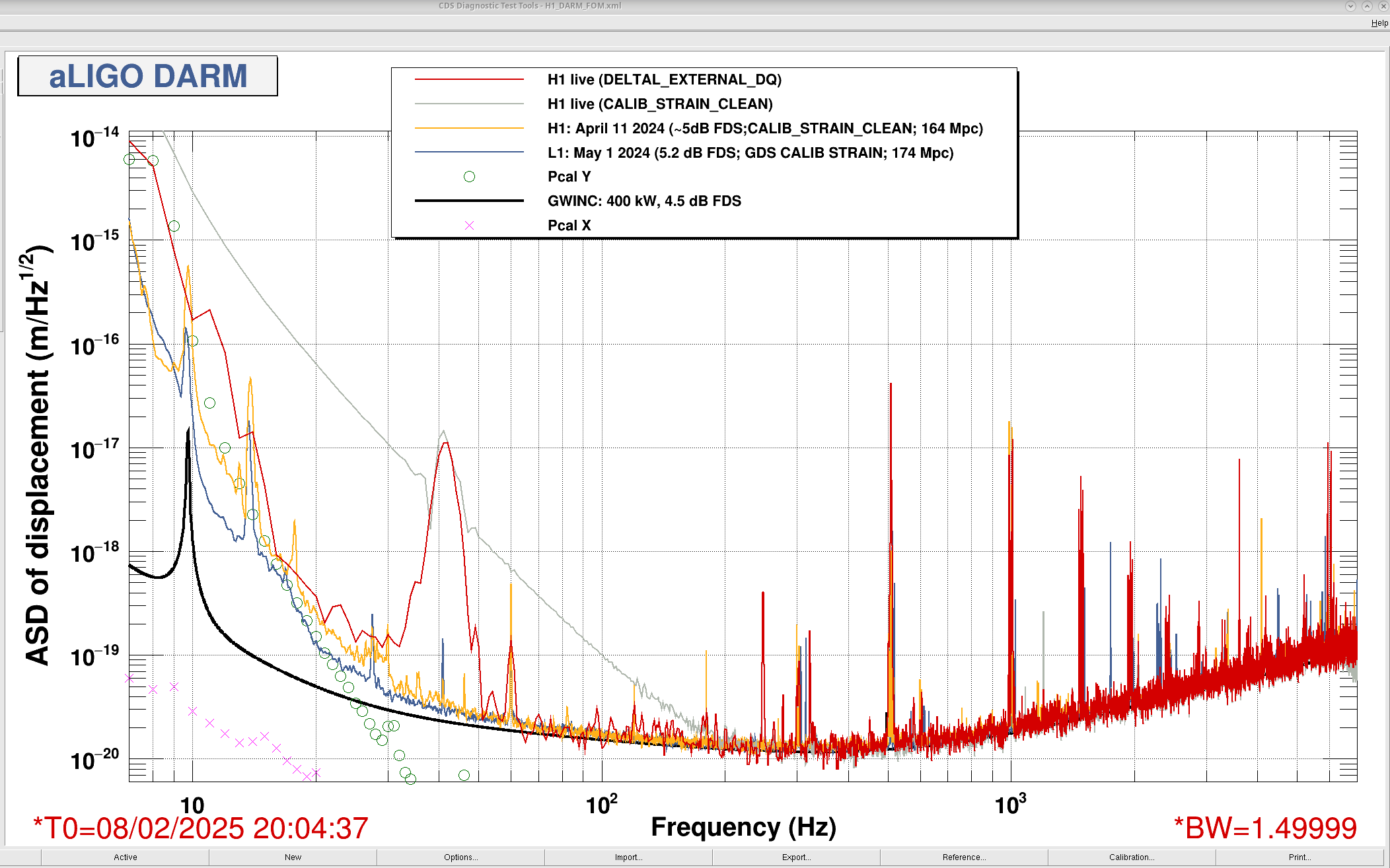
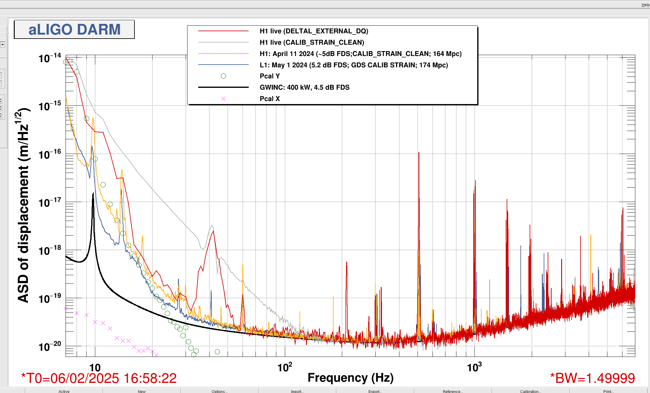
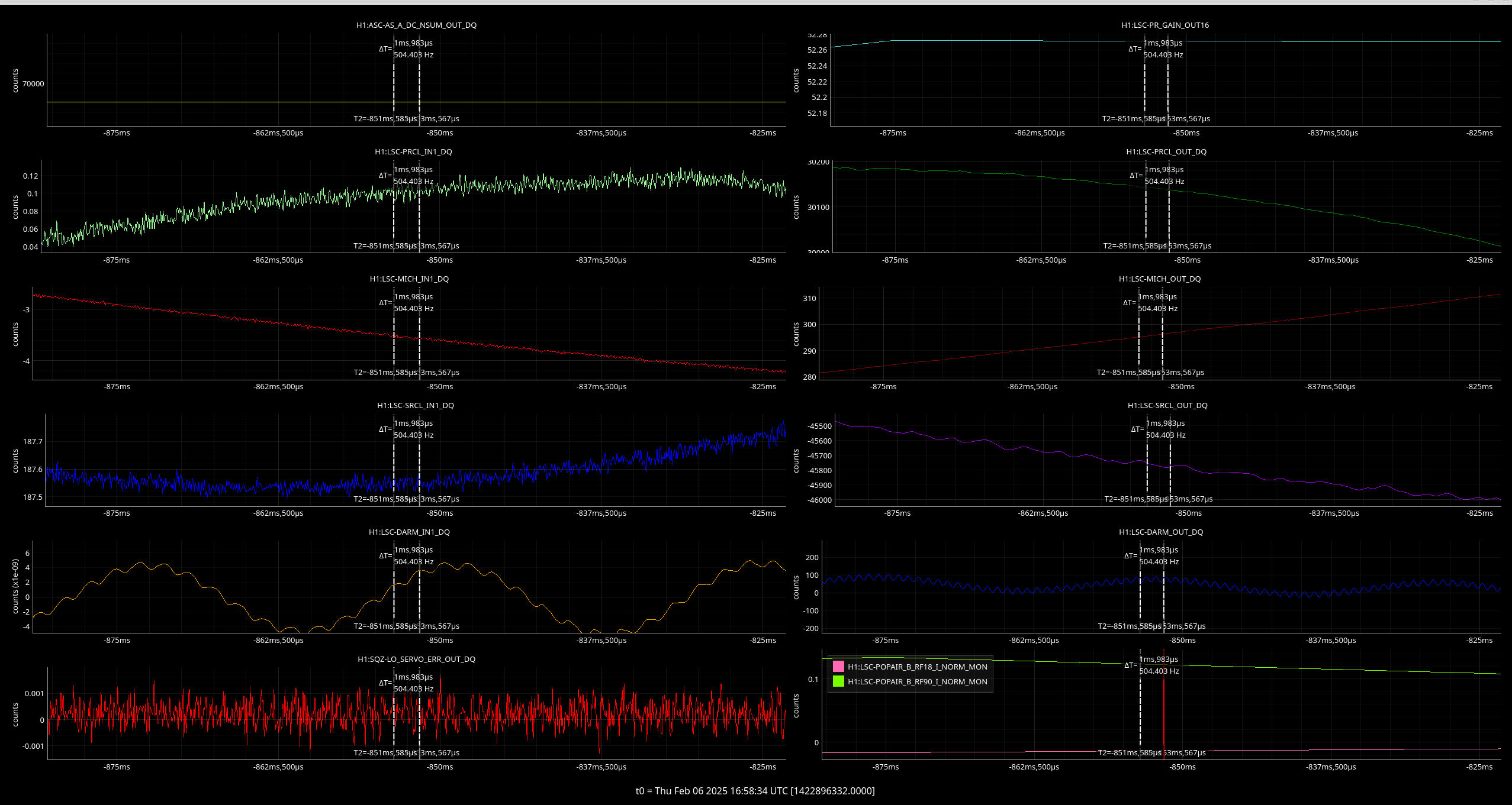
I took a look at the locklosses during the calibration measurements the past week. Looking at DARM right before the locklosses, both times a large feature grows around ~42 Hz right before the lockloss. Sat LL Thur LL
Thursday:
DARM_IN was dominated by the 42 Hz long oscillation and a ~505 short oscillation until the LL, DARM_OUT was dominated by the harmonic of the violins ~1020 Hz.
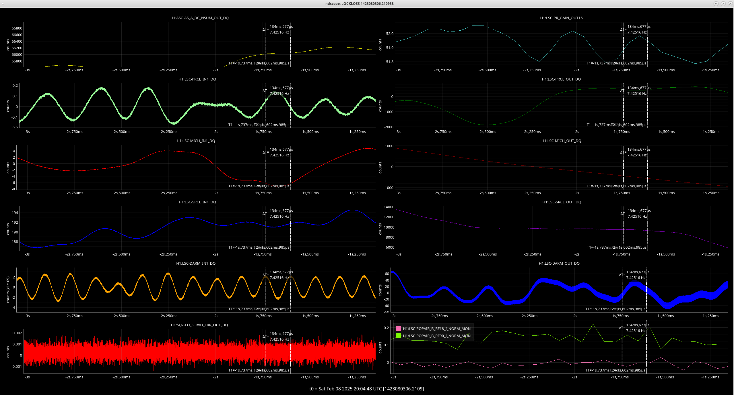
Saturday:
DARM_IN had a long and a short oscillation, the fund violin modes, ~510 Hz and ~7.5 Hz, DARM_OUT was dominated by the harmonic of the violins ~1020 Hz
I'm not sure how to/where to see exactly what frequencies the simulines were injecting during and before the lockloss.

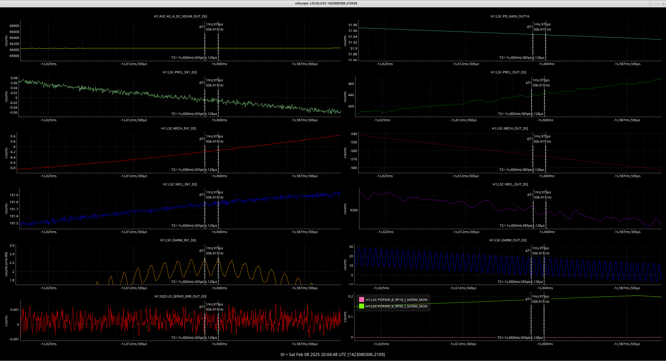
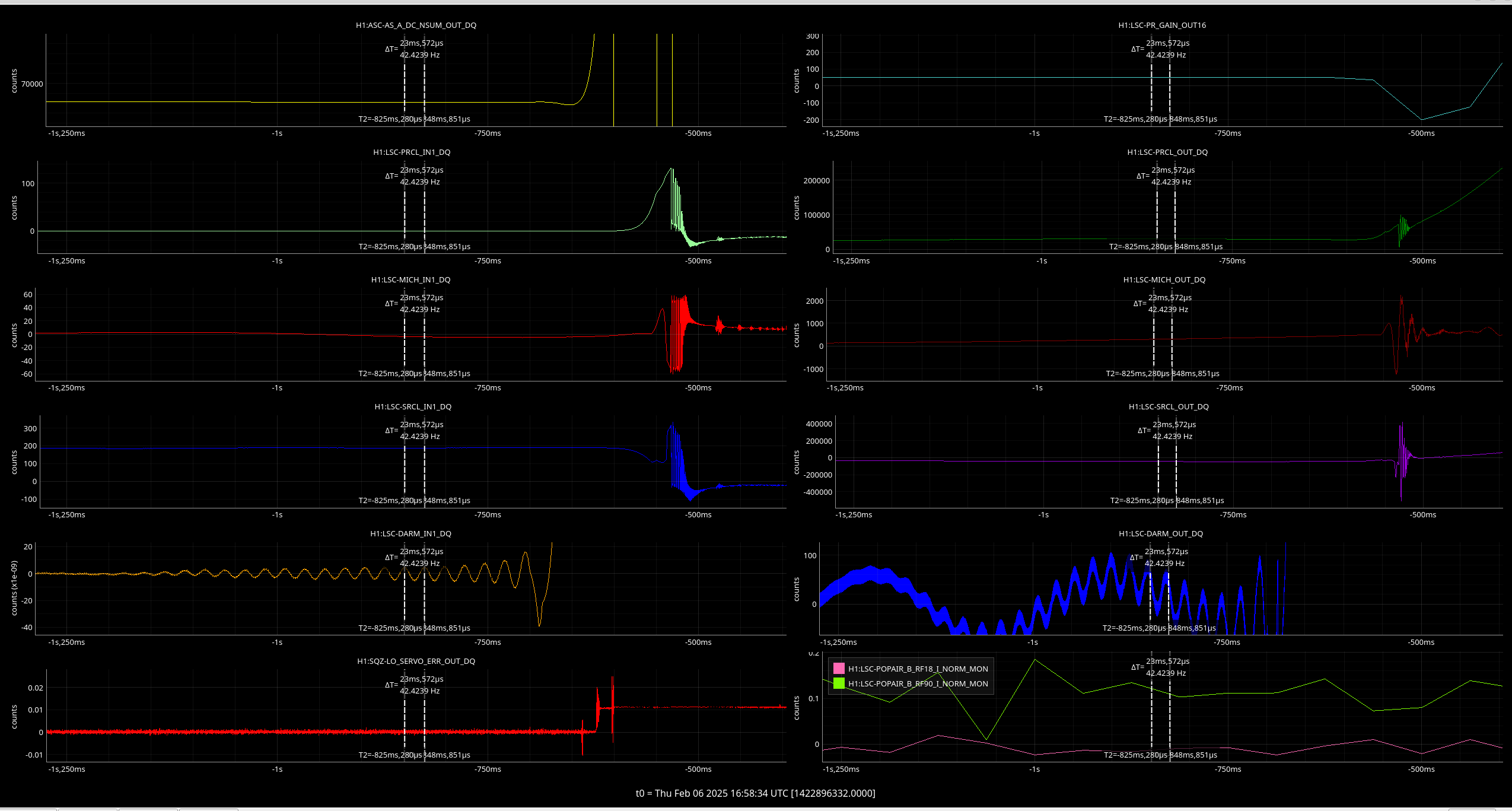


Looking into what's going awry.
I pushed for a change of calibration sweep amplitudes on the Pcal and the PUM (which had been tested a couple of month's back) which was instilled into the calibration sweep wiki last week, labeled informatively as "settings_h1_20241005_lowerPcal_higherPUM.ini".
Both of these sweeps were very near the end, where Pcal is driving at 7.68 Hz and PUM is driving at either 42.45 Hz or 43.6 Hz, which should clarifiy the source of the signals you are pointing out in this aLog.
The driving amplitude of the Pcal at 7.68 is about 20% lower than the injections that were being run the week before, deliberately done to reduce kicking the Pcal during ramping to reduce broad band coupling into DARM which would affect other measurement frequencies like the L1 which is driving at ~12 Hz at this time.
The driving amplitude of the PUM at ~42 Hz is unchanged from injections that had been running up until last week.
Not seeing any SUS stage saturating at lock losses. Presently unconvinced lock losses are related to new sweep parameters.
Both locklosses coincided with the ramping ON of the final DARM1_EXC at 1200 Hz
Tagging CAL properly
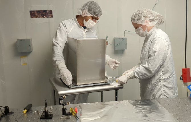
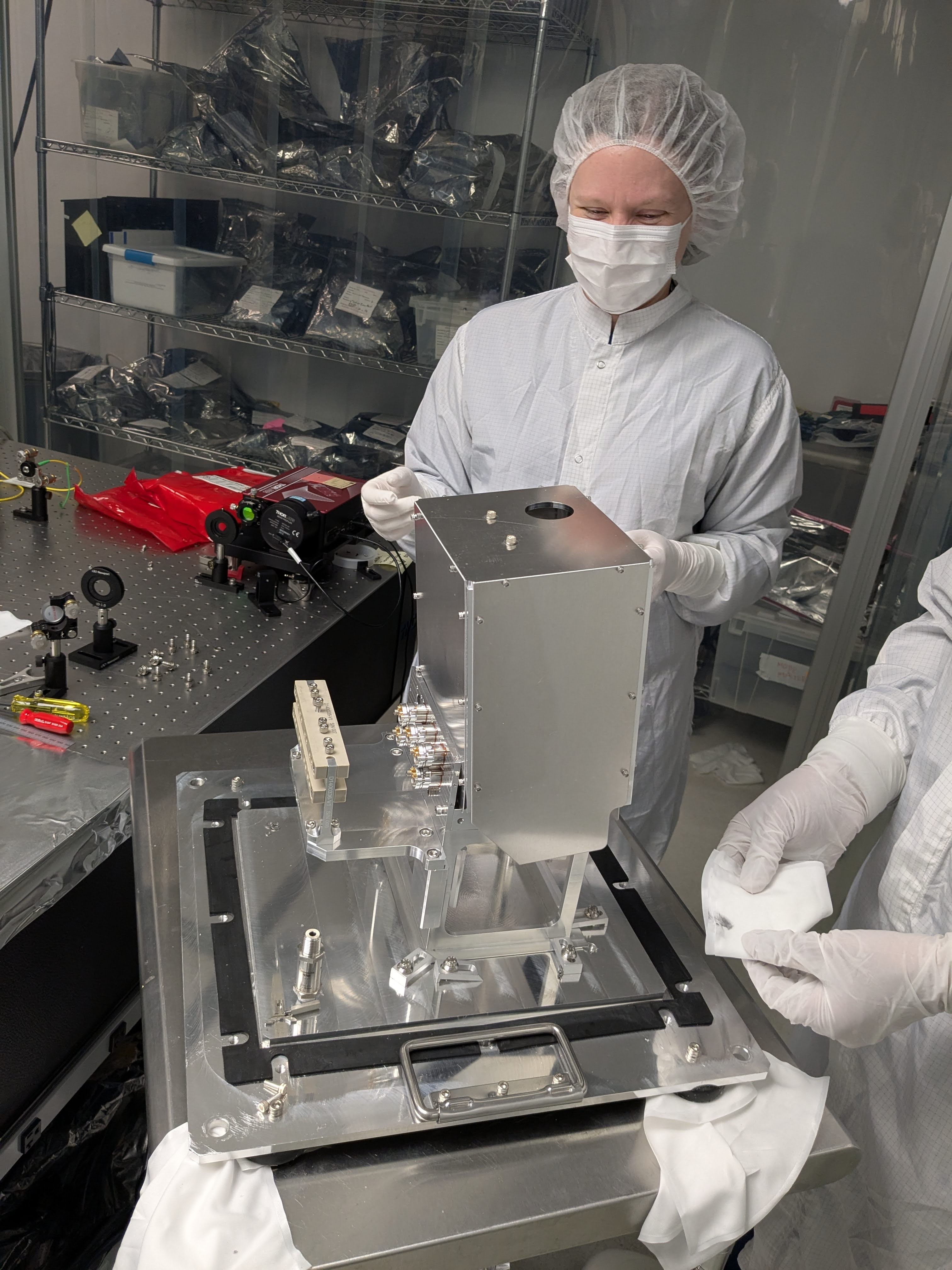
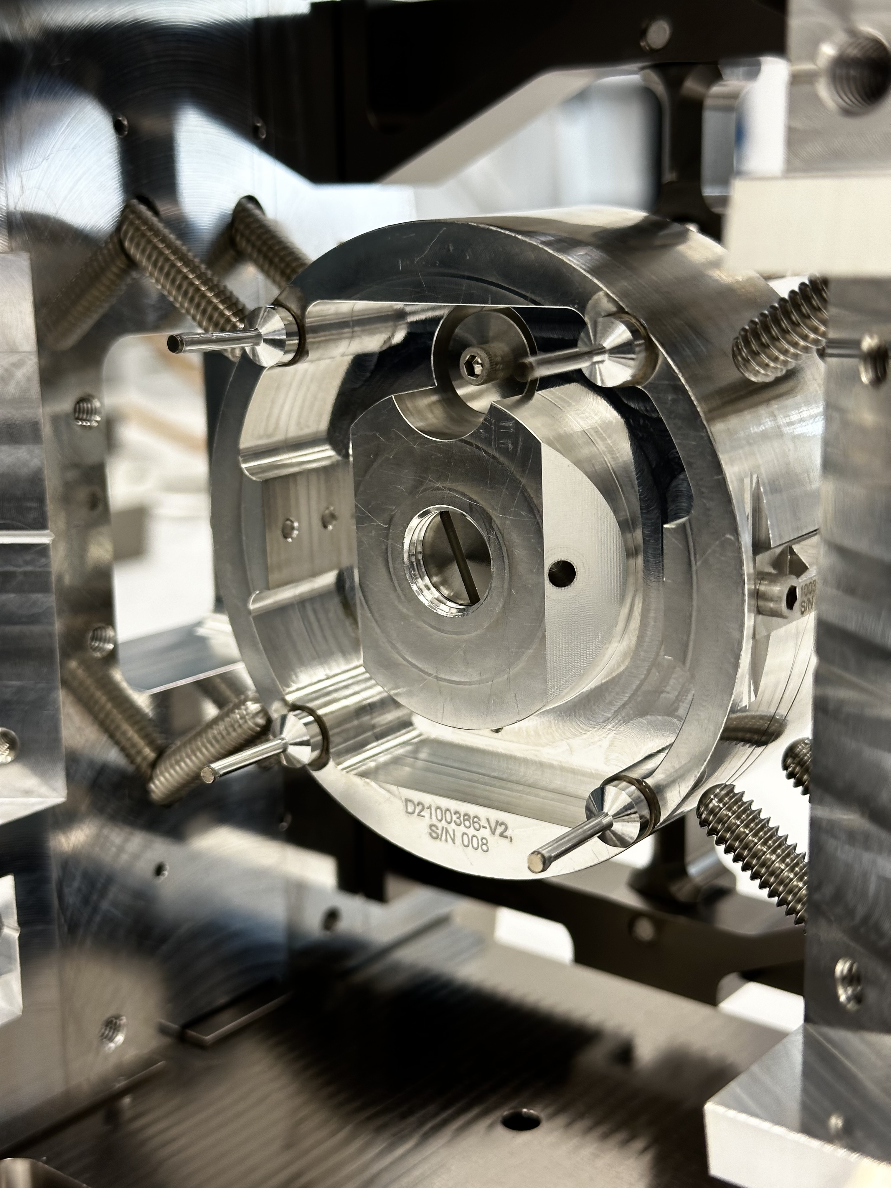
To rebuild the spare ISS PD Array unit (D1101059 S1202967, note that I myself don't have an access right for the S-number document on DCC) and align the PDs, we opened the transport container (D1400368) in the optics lab.
We initially had a hard time to open the container as the viton gasket (D1400366) was REALLY firmly stuck to the container lid (D1400367) and the container base (D1400365). We put the container on top of small stainless steel cart and used screwdrivers to pry the cover off from the base plate. Even after two corners were freed, we could not lift the lid just by hand, and we had to continue prying the lid until all four corners were freed.
Contamination:
After finally removing the lid, we found two bases for concern, the first is the contamination.
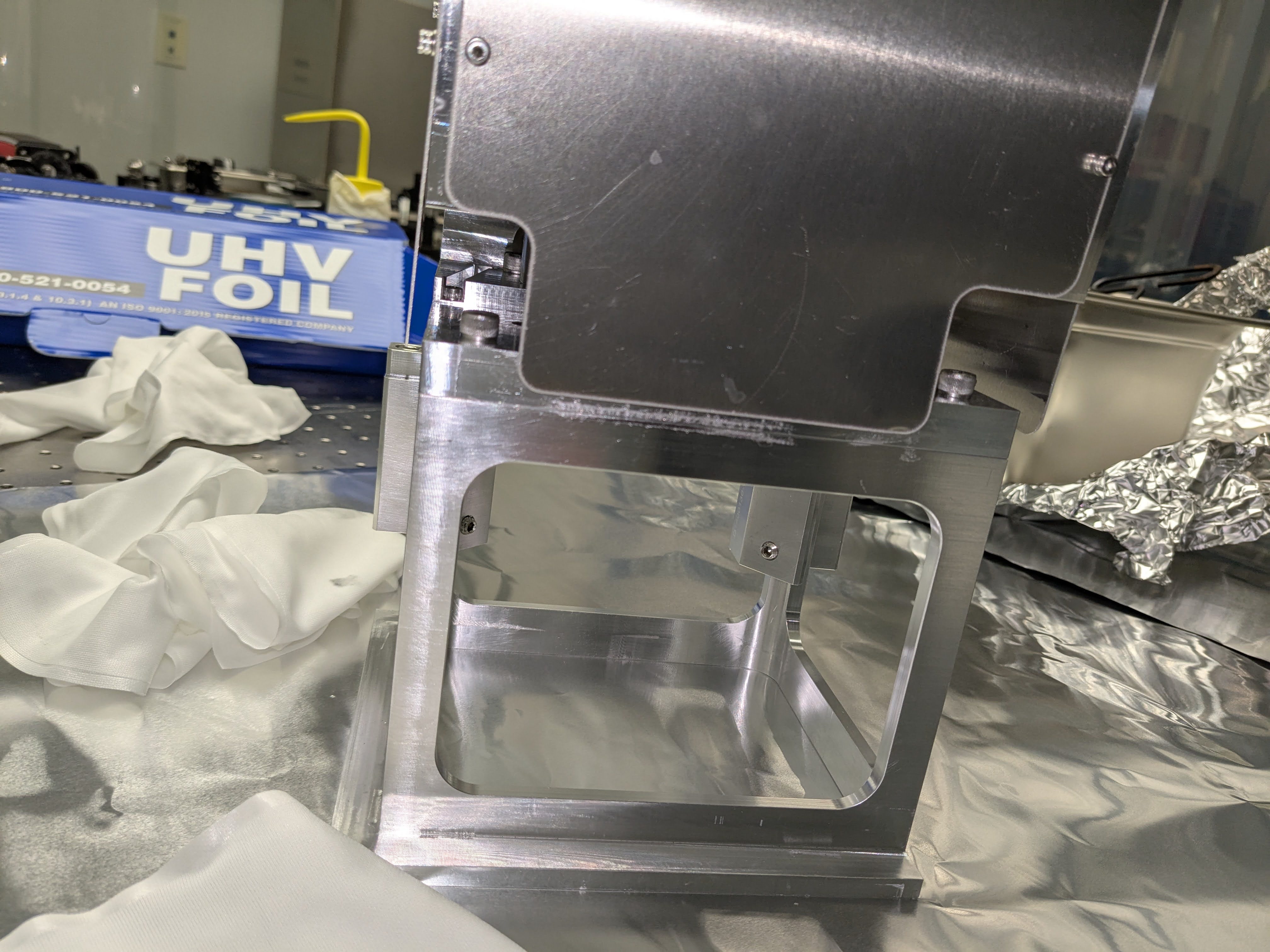
The first two pictures shows the container assembly before and after removing the lid.
Note that the second picture shows the class A "cover" for the assembly tilted back. It turns that the cover was just put there, free to rattle. Connection rods that are supposed to attach the cover to the cage structure were not bolted to the cage.
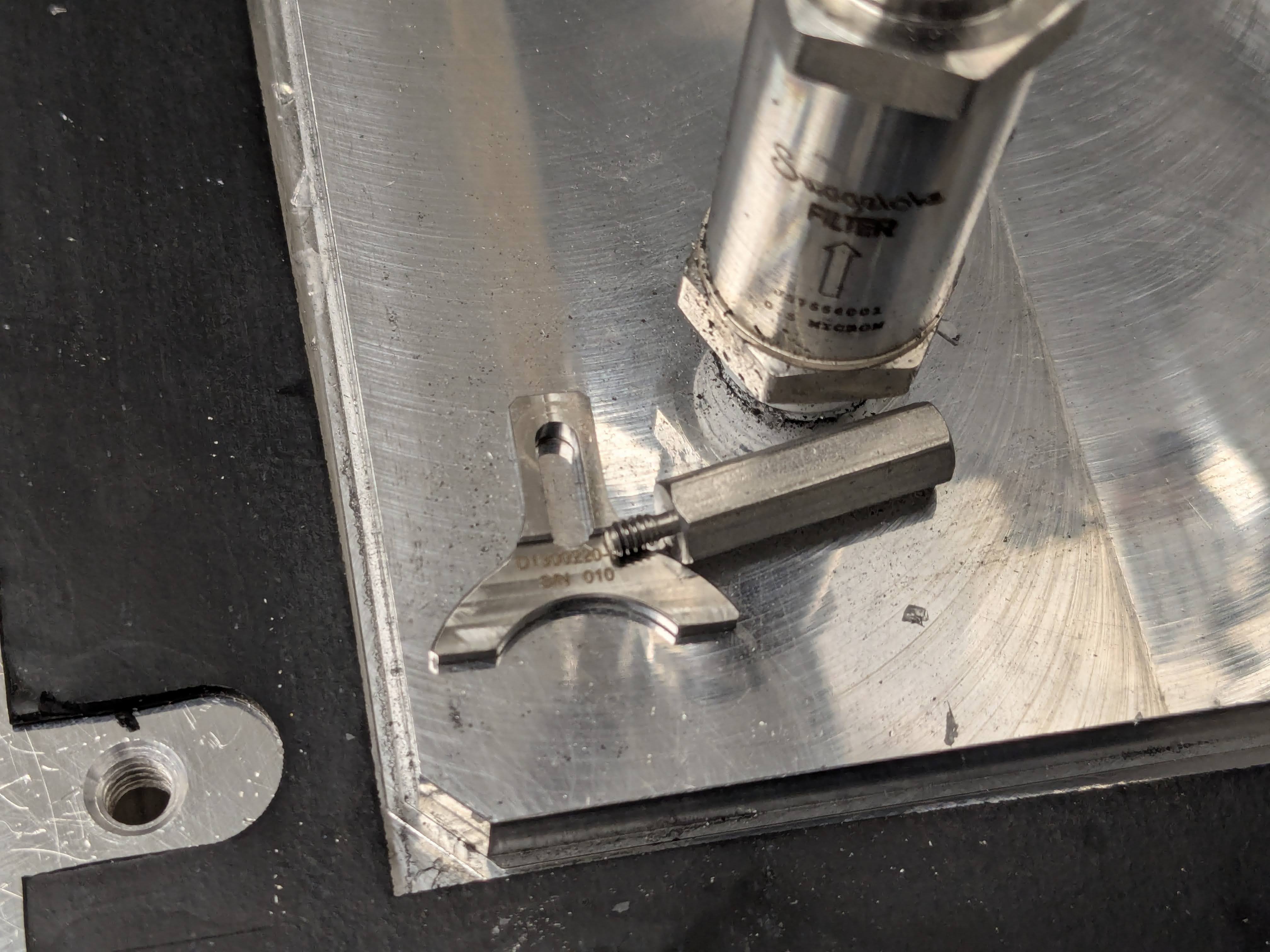
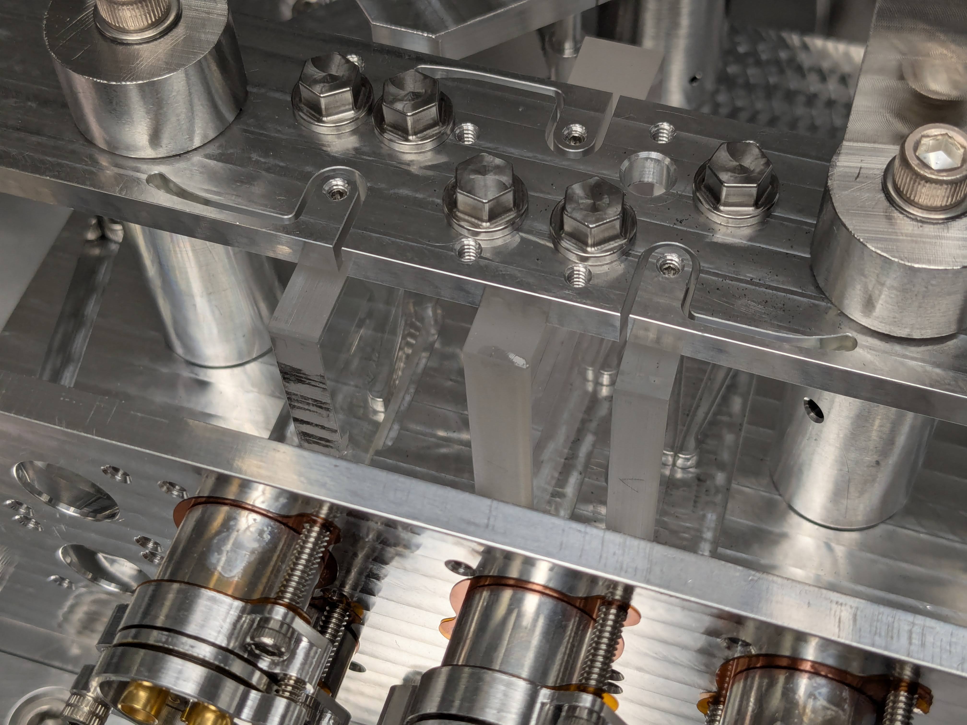
The third picture shows how filthy the container base plate was. It also shows a half of QPD retainer parts that were found there, next to a swagelock fitting attached to the base plate.
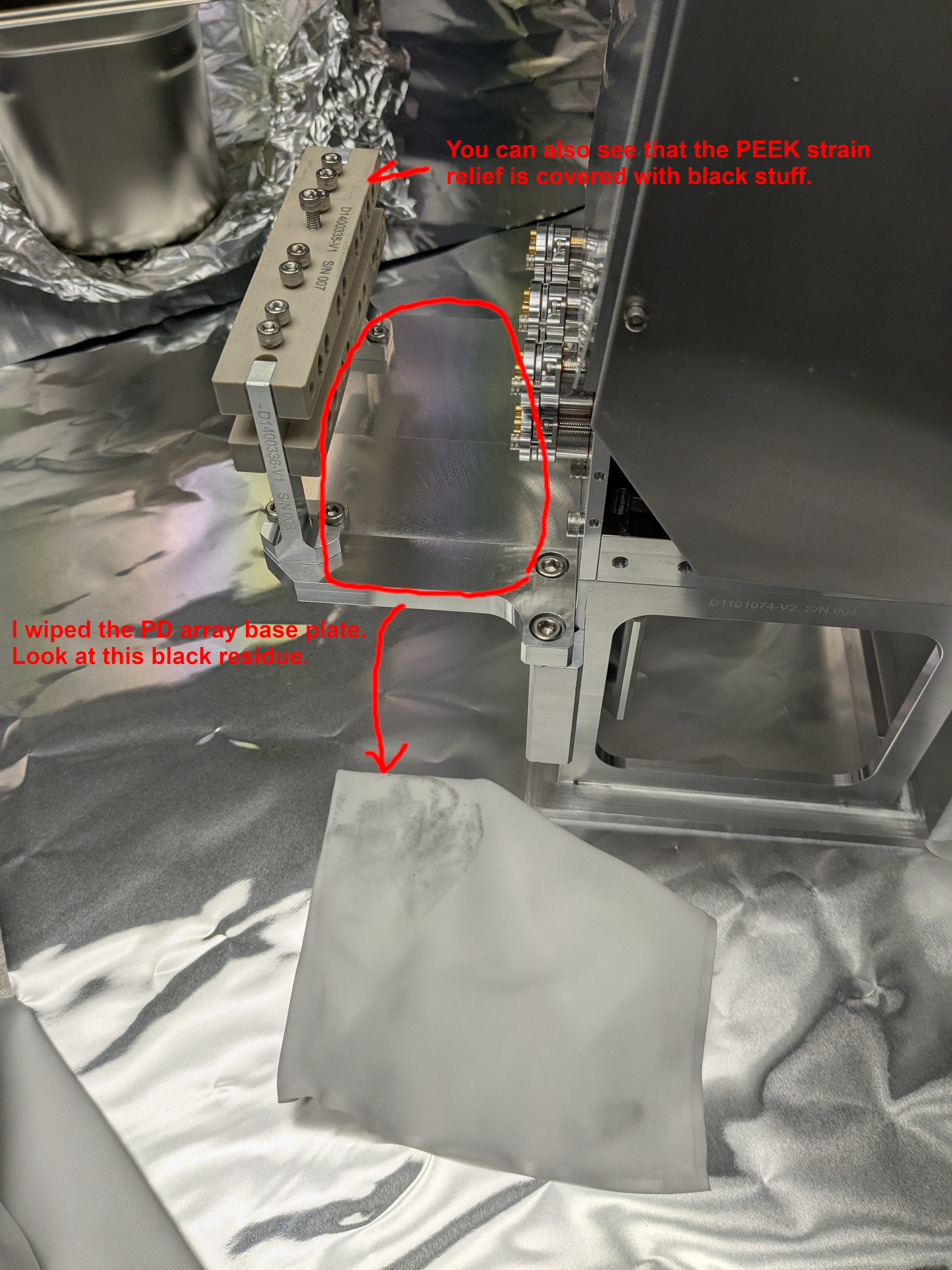
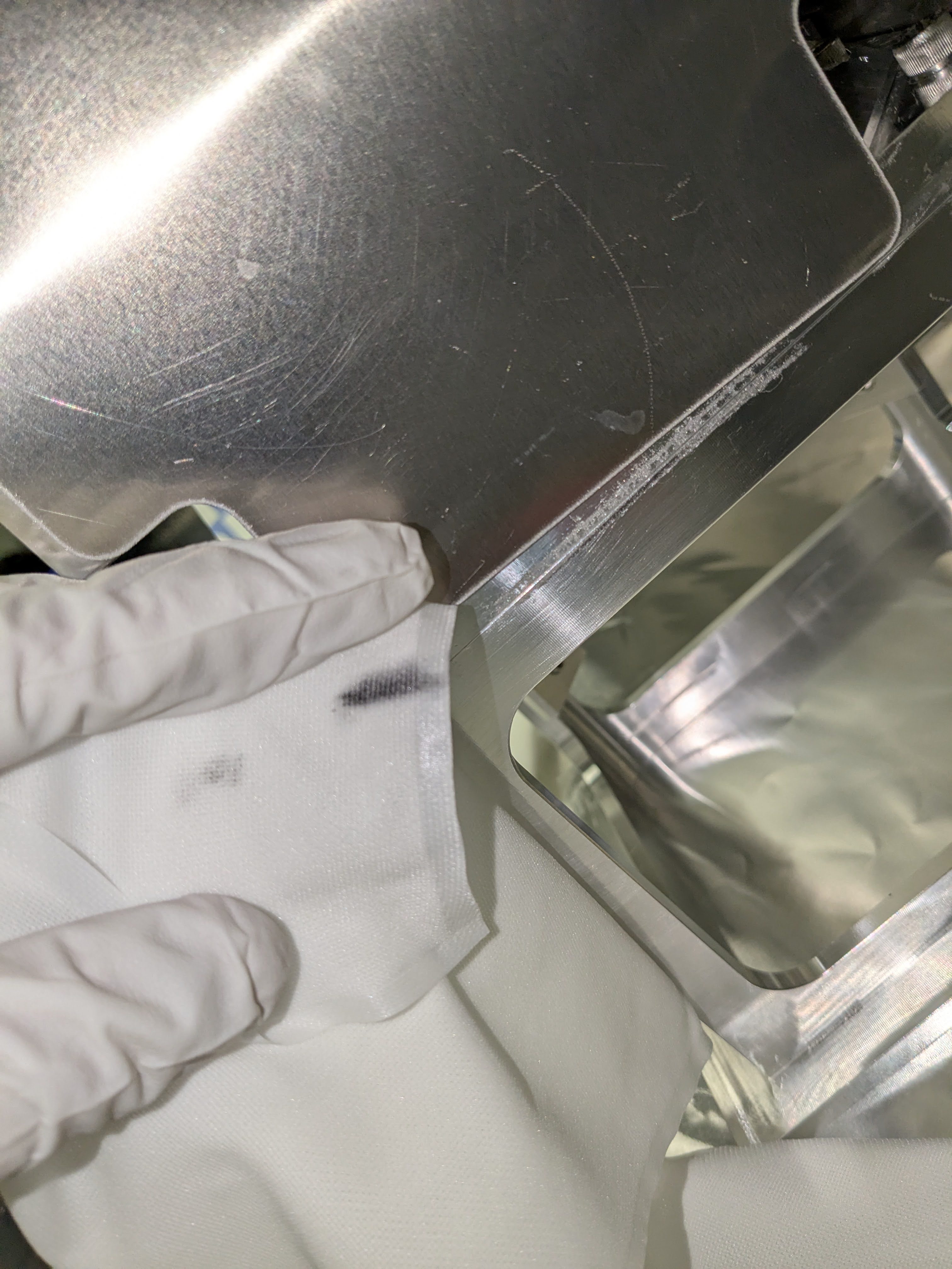
Fourth picture shows the pre-soaked wipe I used to lightly clean the top surface of the PD array base plate. I immediately picked up some black stuff. You can also see that the PEEK parts are covered with black stuff.
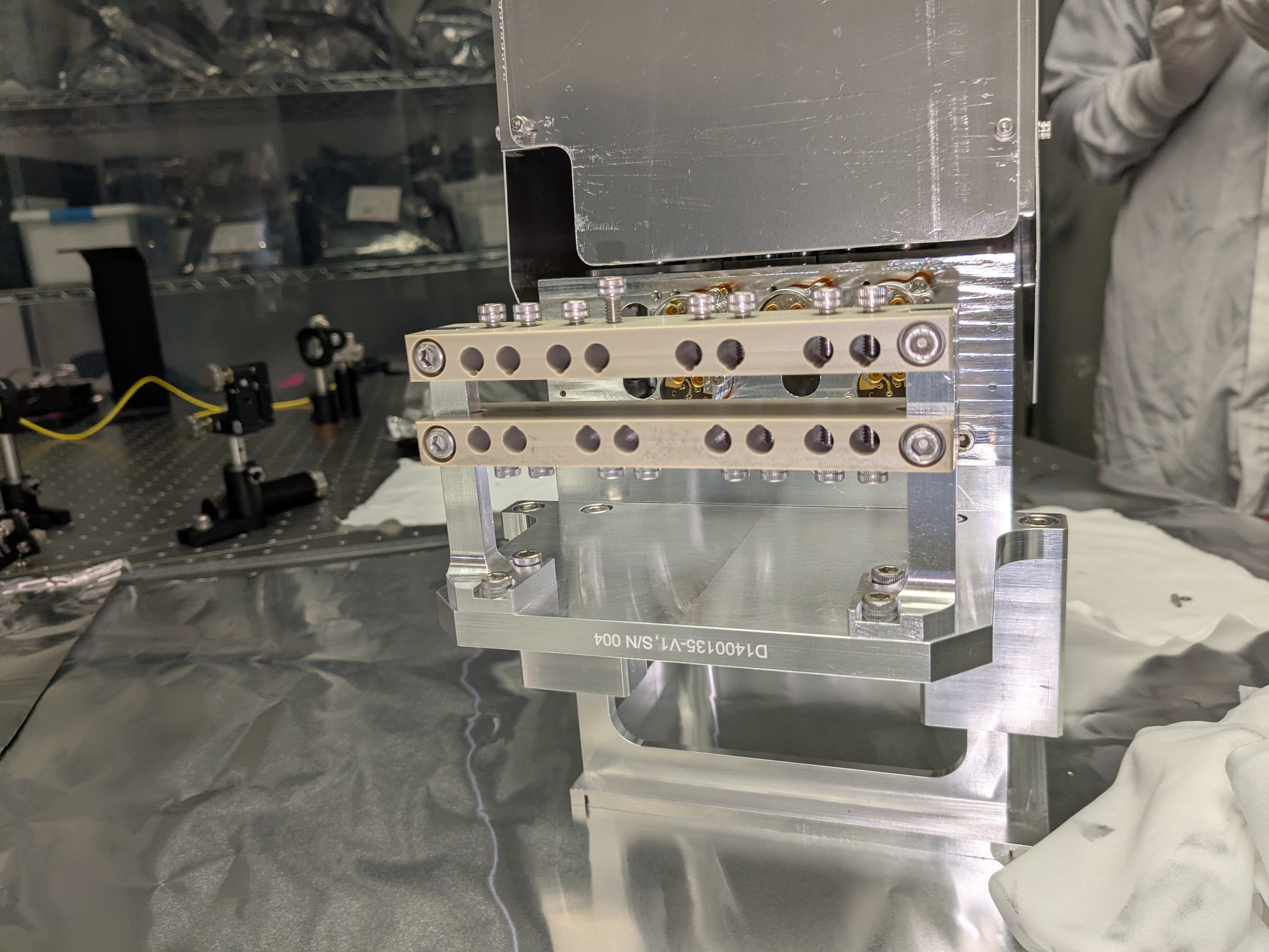
Fifth picture shows the PEEK parts. I wiped the top parts but the bottom one is yet to be cleaned. You can easily see the difference.
6th and 7th picture shows deep scuff on the class A surface of the array PD structure, which seemed to have most accumulated the black stuff.
Glass chipping
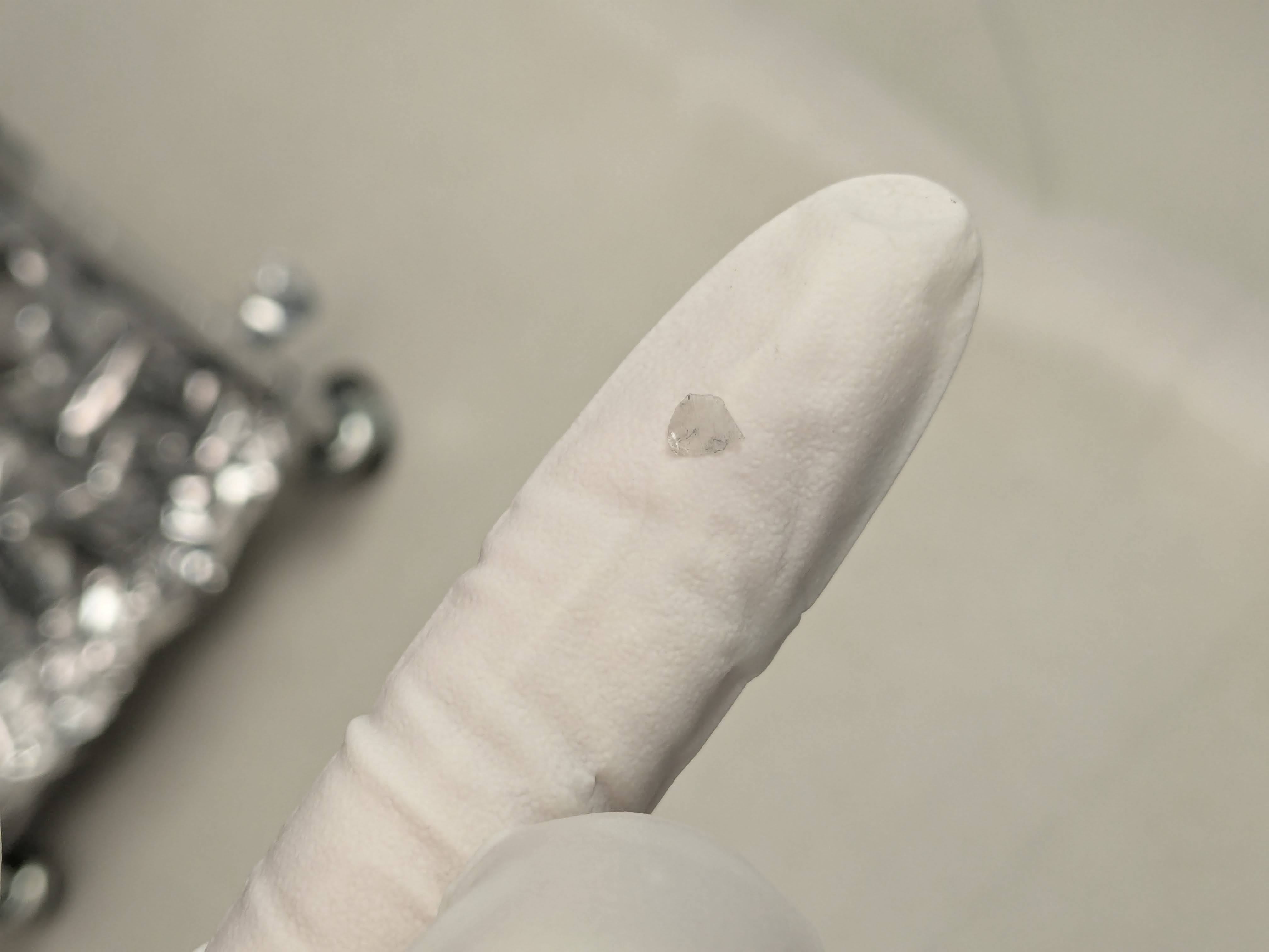
We also found what seemed like tiny pieces of glass on the container base plate as well as the ISS PD base plate.
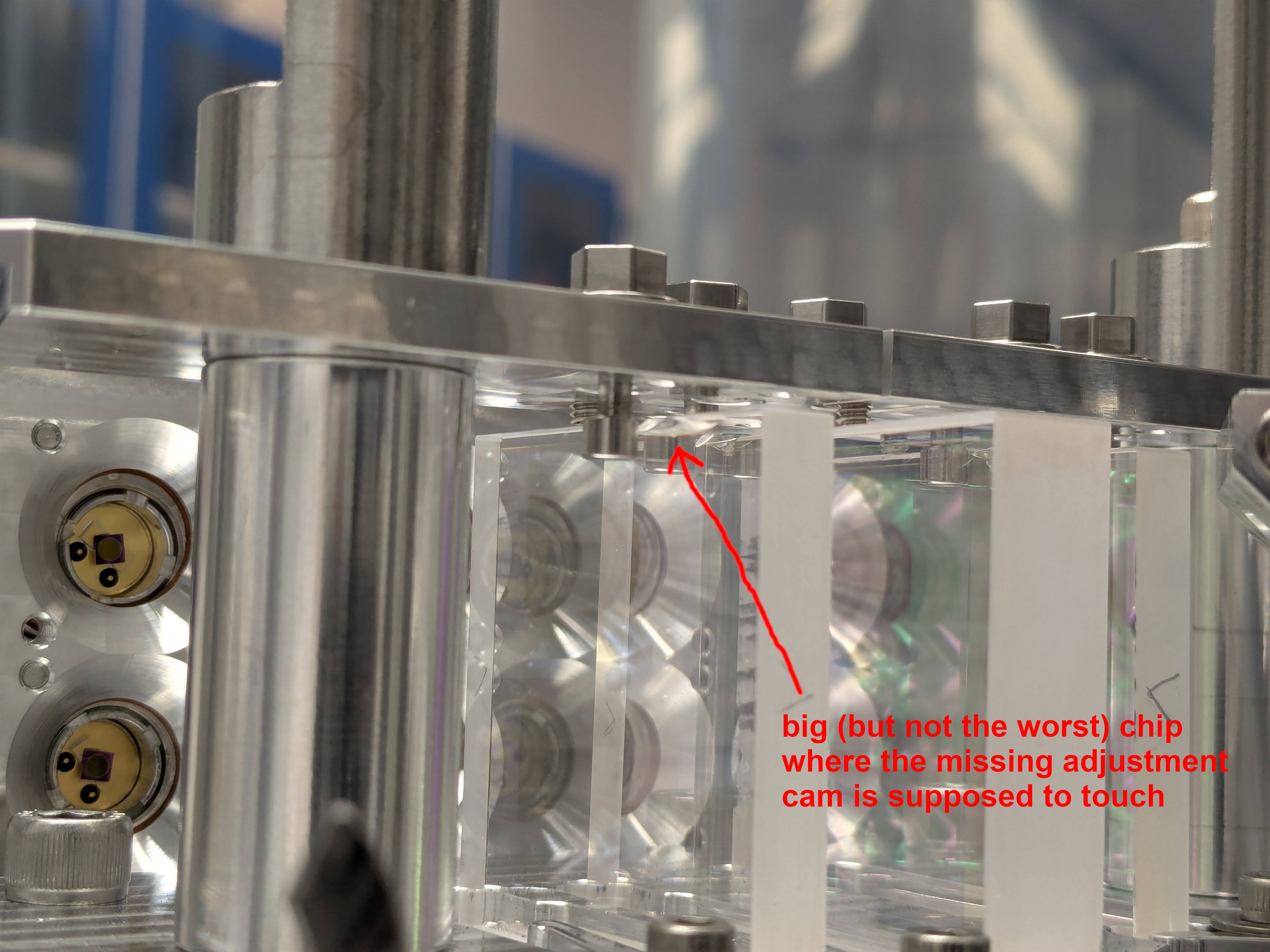
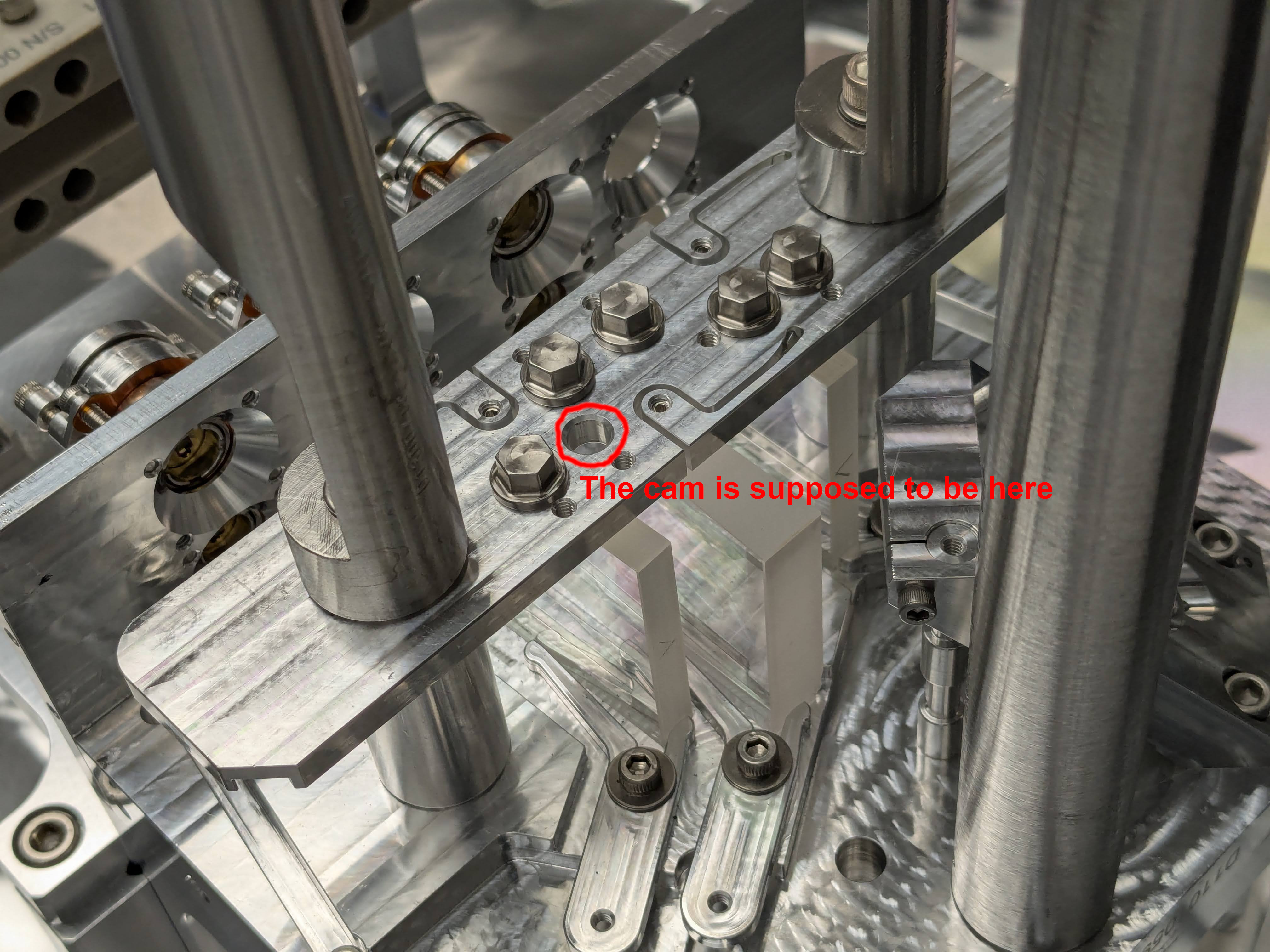
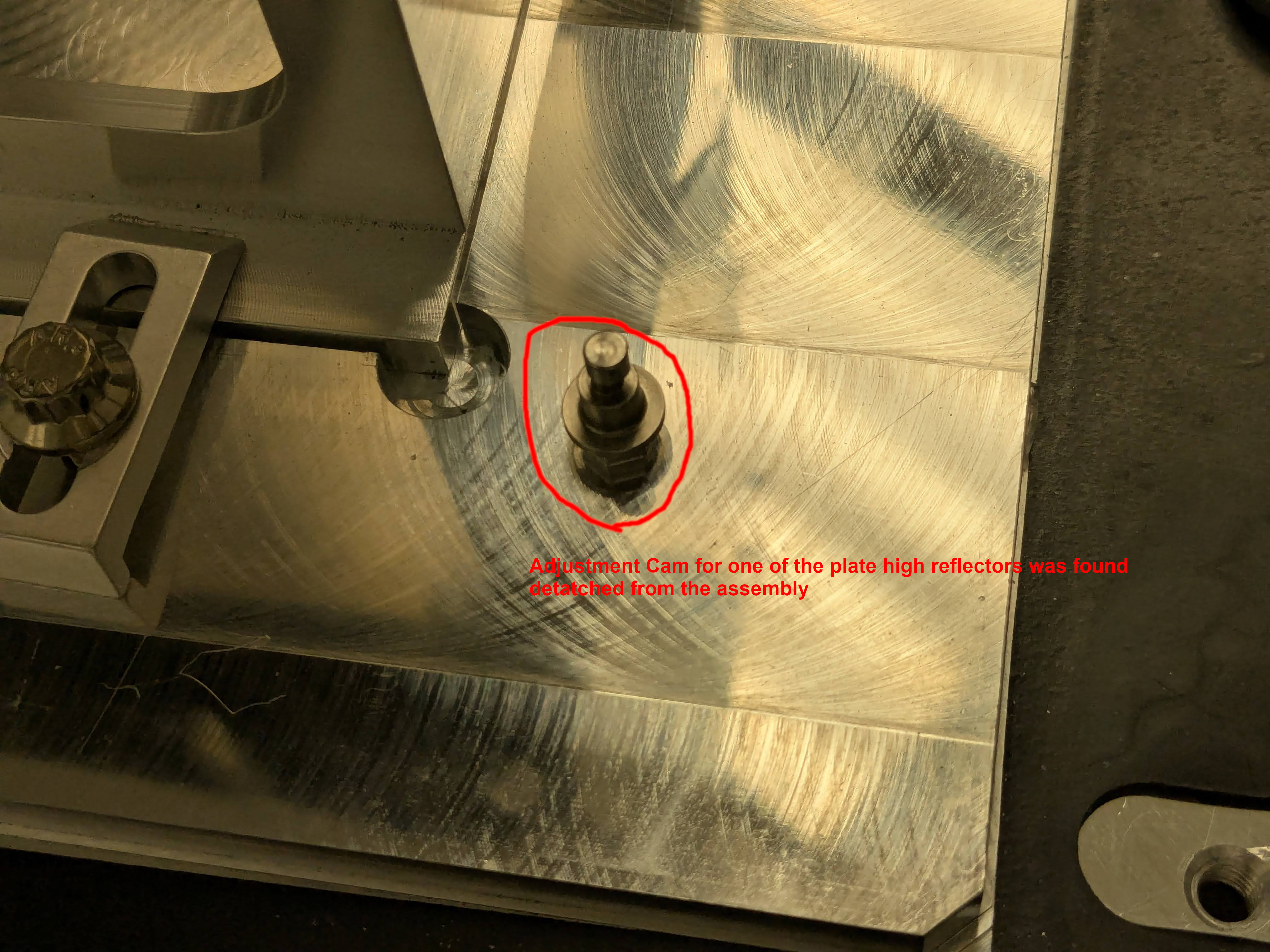
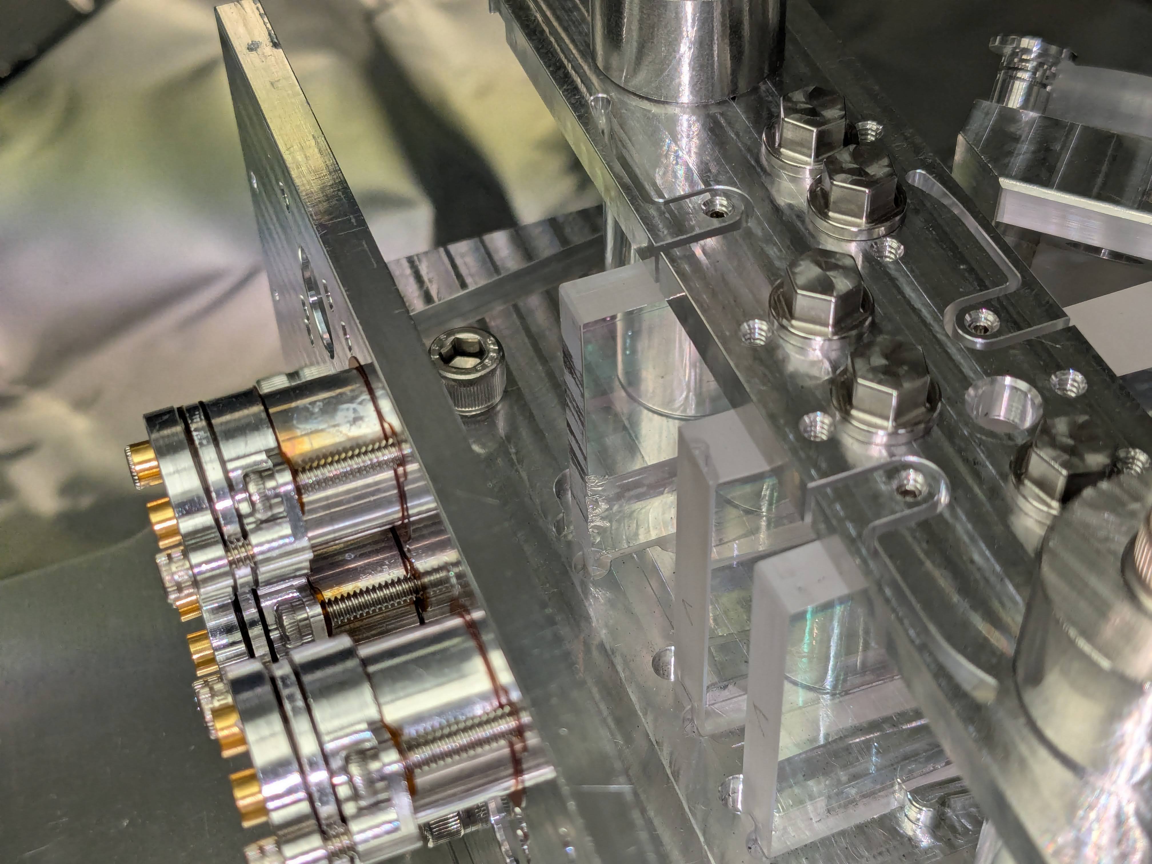
We inspected plate optics and found that all of them have chips. The worst one is one of the high reflectors.
The first three pictures show the damage of the leftmost HR optic seen from the beam entry point (i.e. array PDs are facing you). There appears to be a big chip where the adjustment cam is supposed to touch, but the cam was found detatched from the assembly and was on the transport container base plate.
The fourth picture shows the chip at the corner of the middle optic (BS). It also highlights that what seems to be the deep scuff marks or maybe grinding marks from the manufacturing process on the high reflector to the left (which is a different optics from the first three pictures as you're looking at the assembly from the array PD position so to speak) seem to have accumulated black stuff. That optic also has bad chipping on the front edge, which is more clear on the fifth picture.
The 6th picture shows one of the bigger glass pieces found on the surface of the transport container base plate. Note the black smudge on the glass (if it is glass).
Sheila, Matt Todd
We are having more incidences of the nonstationary noise 20-60 Hz that correlates with the CO2 ISS channel.
Here's a collection of links related to this issue in the past:
Here is a Lasso result for the noisy lock from this weekend: lasso Feb 9. Jane Glanzer is working on running lasso for some of the recent noisy times including the max as well as mean channels, so that may provide additional clues. We still see the ITMX CO2 ISS channel correlated with range. Note, on Feb 7th Lasso chooses H1:IOP-OAF_L0_MADC2_EPICS_CH15 which is the same thing as ITMX_CO2_ISS_CTRL2_INMON,
For the 9th the Rayleigh statistic also clearly shows this issue: summary page for Feb 9th, but comparing this to one of our normal days (range just below 160 and stable on Feb 4th) we also see nonstationarity at these frequencies. So, it is possible that we normally have this non stationary noise at a lower level and it is always limiting our sensitivity.
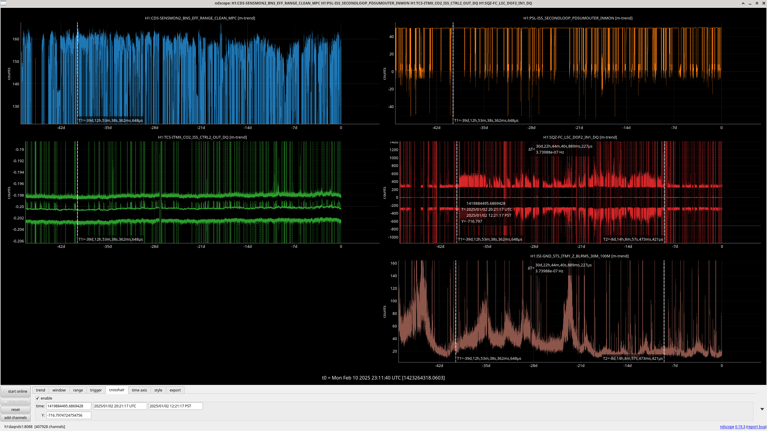
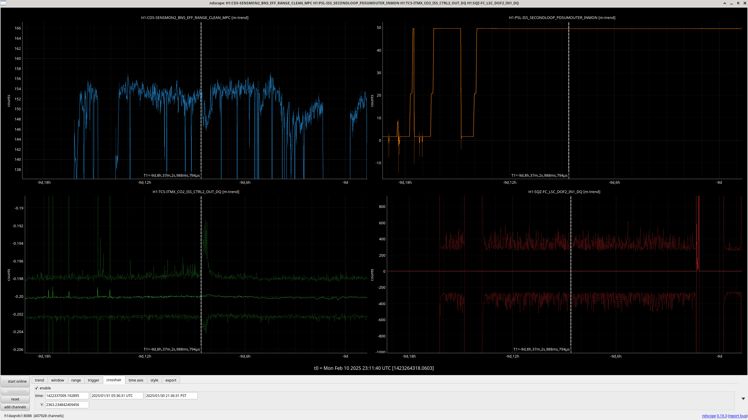
Feb st we had an incident where the ISS CO2 channel was correlated with the range, screenshot. Feb 1st there was also a remarkable change in the FC length control signal peak to peak, which has not shown any correlation with these range drops in the last week and a half, but did last may (78485). Matt found this alog about squeezer issues on the 1st, 82581, we adjusted the SHG temperature, and fiber polarization, and there was a temperature excursion in the FCES. The FC length control signal was noisy from Jan 2nd to Feb 1st, and has been back to normal since.
Operator request: If operators see the range fluctuating with lots of noise between 20-40 Hz, (similar to Feb 9th), could you drop out of observing and go to no squeezing for 10 minutes or so? We would like to see if this problem comes and goes with squeezing as it did last May.

I have run lasso for four different time periods as suggested by Sheila. As mentioned, these lasso runs differ from a traditional run in that I am using .max trends of the auxiliary channels to model the bns range. Below are links to each run, along with brief comments on what I saw.
Feb 1st 10:20 - 18:40: The top channel is a SQZ channel, H1:SQZ-PMC_TRANS_DC_NORMALIZED. H1:ASC-POP_X_RF_Q4_OUTPUT and H1:TCS-ITMX_CO2_ISS_CTRL2_OUT_DQ were also picked out. The CO2 channel is correlated with the bigger dip around ~15 UTC.
Feb 7th 12:21:58 - 15:17:03: For some reason, lasso only runs until 15 UTC, when I have specified it run until 18:30 UTC. I am not 100% sure why this happens. I think it may be because of a large range drop around 15 UTC. I have still included what lasso found for the initial 3 hours or so. Some top channels picked out are H1:SUS-ITMY_M0_OSEMINF_F2_OUT16 & H1:ASC-AS_A_RF45_Q2_OUT16. These are new channels that I don't think have been picked out before. I will say that farther down the list of correlated channels H1:PSL-ISS_SECONDLOOP_QPD_SUM_OUT16.
Feb 7th 21:55:32 - Feb 8th 01:40:00: Top channel is H1:TCS_ITMX_CO2_ISS_CTRL2_OUT_DQ.
Feb 9th 07:04:07 - 11:59:26: Top correlated channels are H1:PSL-ISS_SECONDLOOP_PDSUMOUTER_INMON & H1:TCS-ITMX_CO2_ISS_CTRL2_OUT_DQ. These are also the top two channels from the regular lasso run (with .mean trends) as viewed from the summary pages.
The most consistently picked out channel is the ITMX_CO2 channel, but the .max trend method also seems to pick up some PSL, SQZ, SUS, and ASC channels as well.
TITLE: 02/10 Eve Shift: 0030-0600 UTC (1630-2200 PST), all times posted in UTC
STATE of H1: Observing at 156Mpc
OUTGOING OPERATOR: TJ
CURRENT ENVIRONMENT:
SEI_ENV state: CALM
Wind: 7mph Gusts, 4mph 3min avg
Primary useism: 0.02 μm/s
Secondary useism: 0.39 μm/s
QUICK SUMMARY:
TITLE: 02/10 Day Shift: 1530-0030 UTC (0730-1630 PST), all times posted in UTC
STATE of H1: Observing at 155Mpc
INCOMING OPERATOR: Ryan C
SHIFT SUMMARY: Commissioning this morning and a few lock losses. The PR2 spot was moved again so the lock reacquisition was slower since Sheila needed to pico for POP QPDs. Other than that relocking has been automated.
LOG:
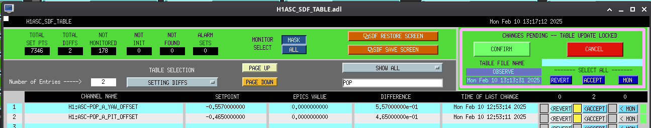
H1 back to observing at 21:18 UTC following commissioning time. Were getting some DIAG_MAIN notifications after going to max power about the POP X PZT being railed; Sheila says we should fix this but can wait for now. The TMS_SERVO Guardian has a note about this being due to different PR3 alignment.
Accepted new POP_A offsets of 0 in ASC OBSERVE.snap table once at NLN (screenshot attached).
J. Freed
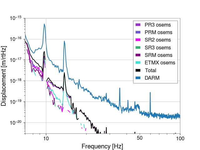
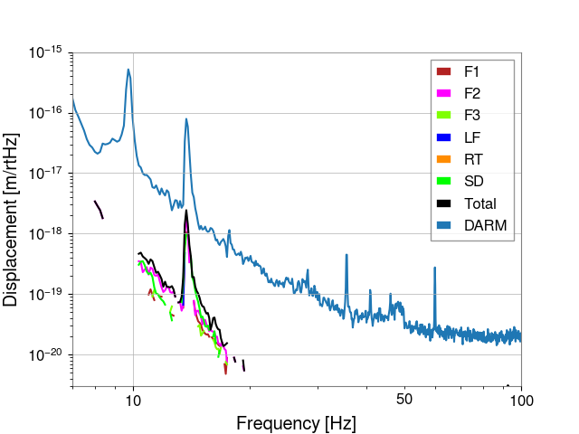
ETMX shows strong coupling of BOSEM noise between 10-20Hz by about a factor of 30 below DARM from most sensors.
Today I did damping loop injections on all 6 BOSEMs on the ETMX M0. This is a continuation of the work done previously for ITMX, ITMY, PR2, PR3, PRM, SR2, SR3, and SRM. As with PRM, gains of 300 and 600 were collected for SR3 (300 is labled as ln or L). Calibration lines were off.
Sheila, Matt T, Mayank, Jennie W
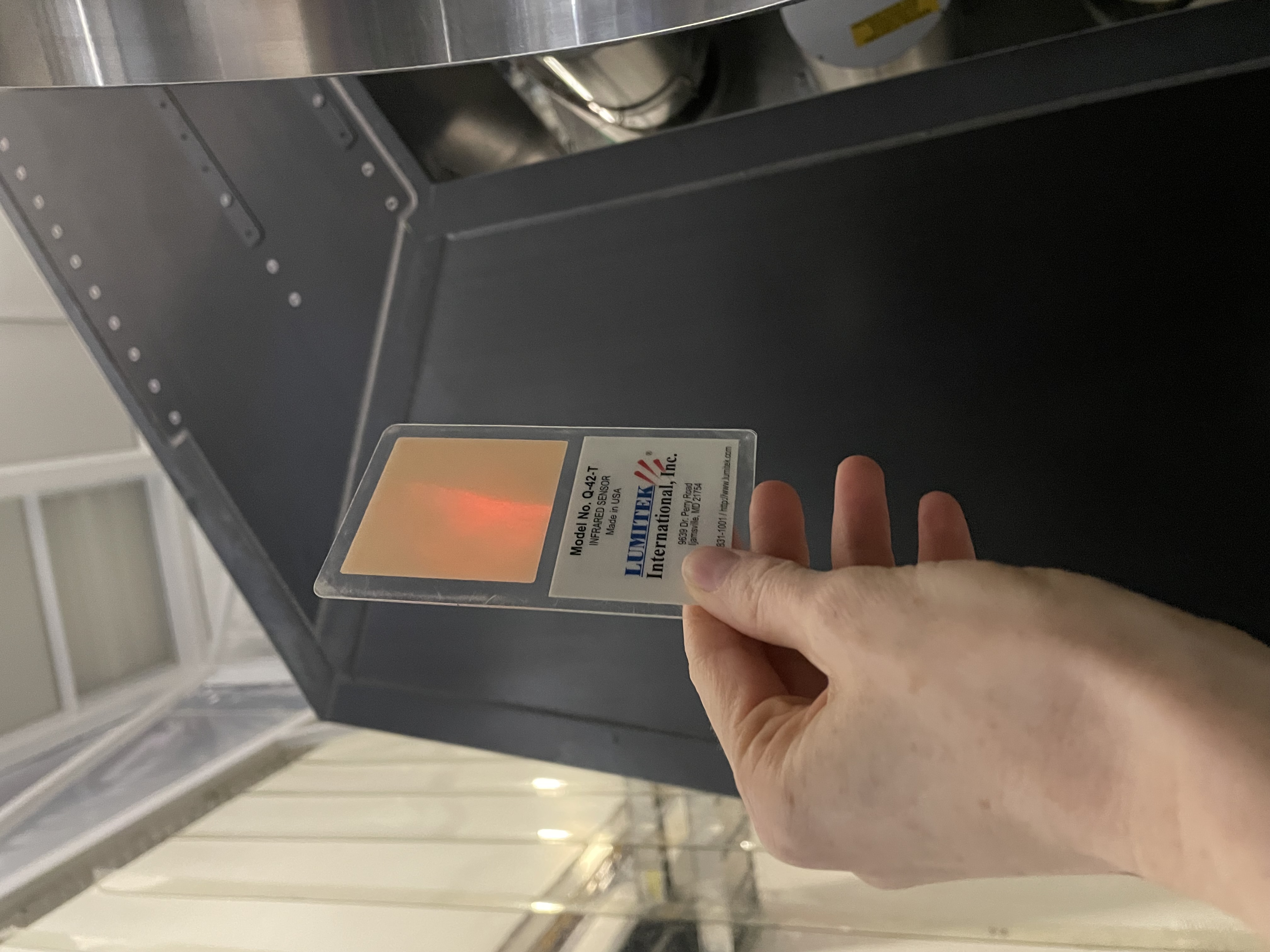
tl;dr: After previous PR2 moves last week, we measured the spot clipping on scraper baffle (and exiting HAM3 viewport) to be 8mW in lock. After measuring this we unlocked for unknown reason and so team PR2 moved 6mm towards the centre of PR2 in yaw while unlocked. We estimate we are roughly centred on PR2 now.
Today Sheila and I measured the spot coming out of the HAM3 viewport as was done by Robert in this entry. The process is replace the black glass guillotine with lexan guillotine, take off the illuminator, clip a lens on a stalk to the top of the guillotine and align this with the beam coming out of the viewport. Not all the light is now captured by the lens as the spot is now more a semi-circle of a clipped beam. We moved the power metre behind the lens till we found the max power we could get on the power metre. This was 8mW and the PR3 yaw slider was at around -74 microradians.
After we came back to control room the IFO lost lock so it was decided to move towards the centre of PR2 which had been measured by Sheila using an A2L measurement at the start of the commissioning period.
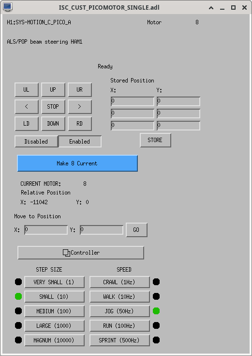
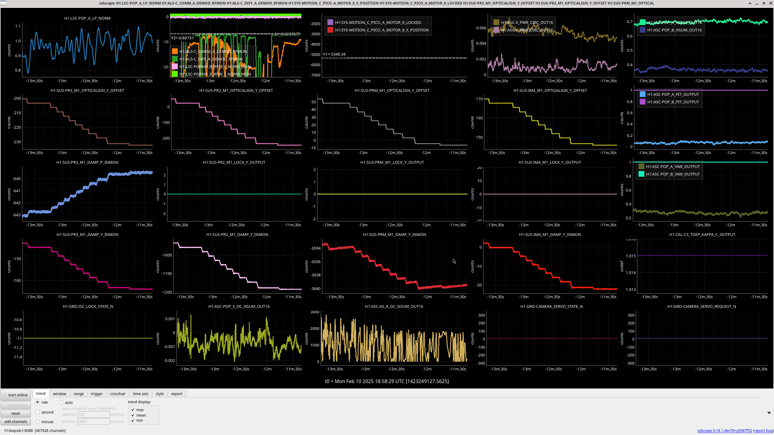
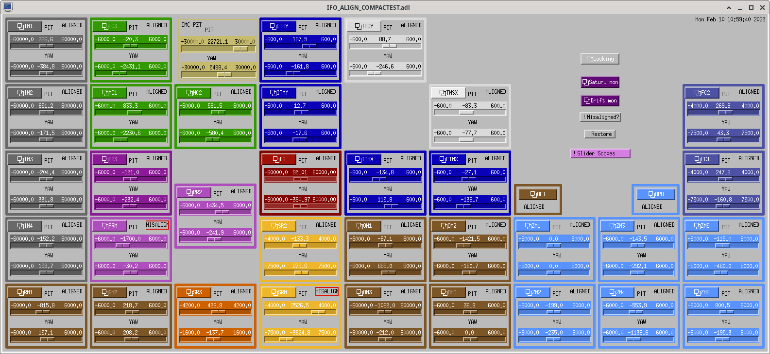
Matt tuned down on PR3 yaw in 3 microradian steps to -232.4 microradians. Each step he tuned the 8X picomotor to bring back the DIFF and COMM ALS beatnotes. Every so often it is also neccessary to step up the pitch on PR3 to compensate for the cross-coupling of yaw to pitch. The ndscope image for the moves is here. Matt left the picomotor like this and the sliders like this.


Before today's move PR3 yaw slider was at -74, where we measured the Y2L coefficent to be -3, which corresponds to 6 mm.
We moved using the procedure in 82670, and we decided to move to -230urad on the PR3 yaw slider based on the table in 82688.
We did go to ISCT1 ad fix up the beatnotes, and TJ stopped at PREP_DC_READOUT where I pico'd to center on the POP QPDs. The centering actually could be better, with POP A well centered POP B is at -0.5 in pitch and -0.1 in yaw at 2W with all ASC on. We can fix this another day, but didn't want to take the time today.
I've set the POP A offsets to 0, accepted this in safe.snap, and added PRC1 and PRC2 in the guardian.
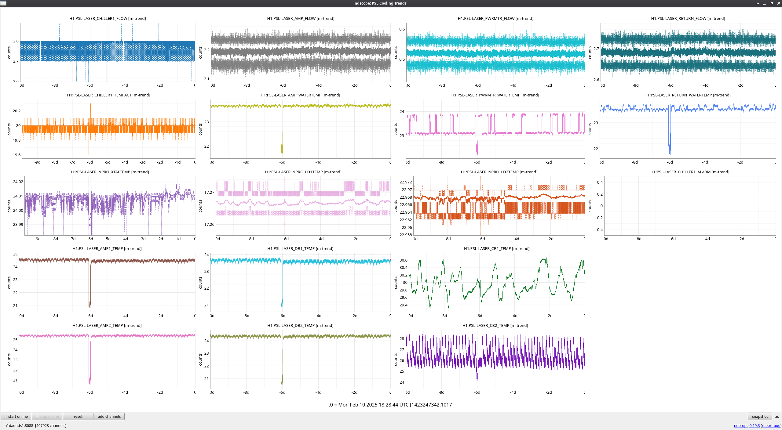
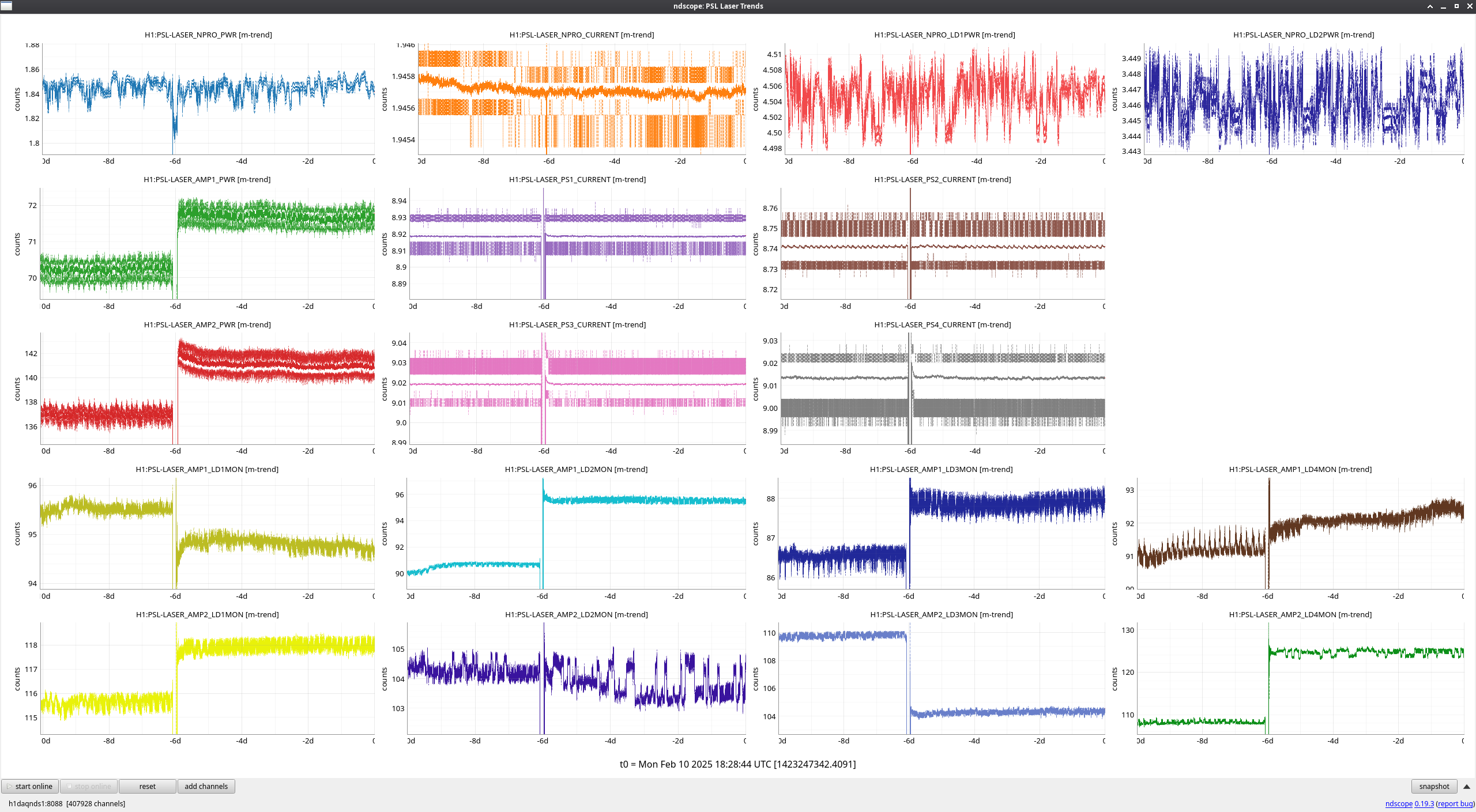
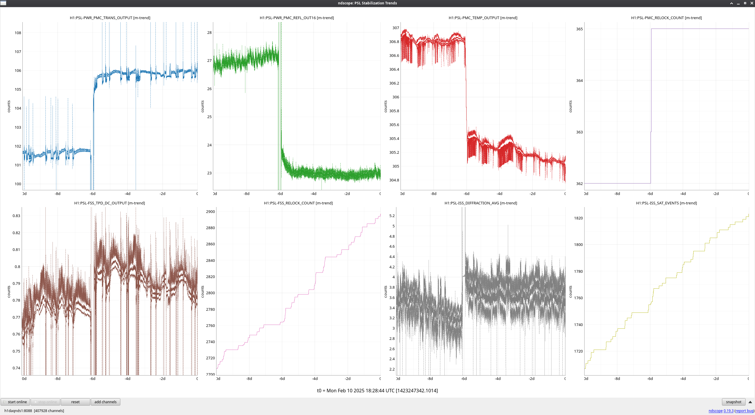
FAMIS 31072
Since our work in the enclosure last week taking pump diode slope measurements (alogs 82636 and 82635), several trends have changes. A majority of the pump diode monitors are at different levels, power out of both amplifiers is higher (AMP2 seems slightly noisier), PMC transmitted power is higher, PMC reflected power is lower and has not been increasing since last week. This is the first time I can recall it not having a steady increase since immediately after the last NPRO swap late last year.
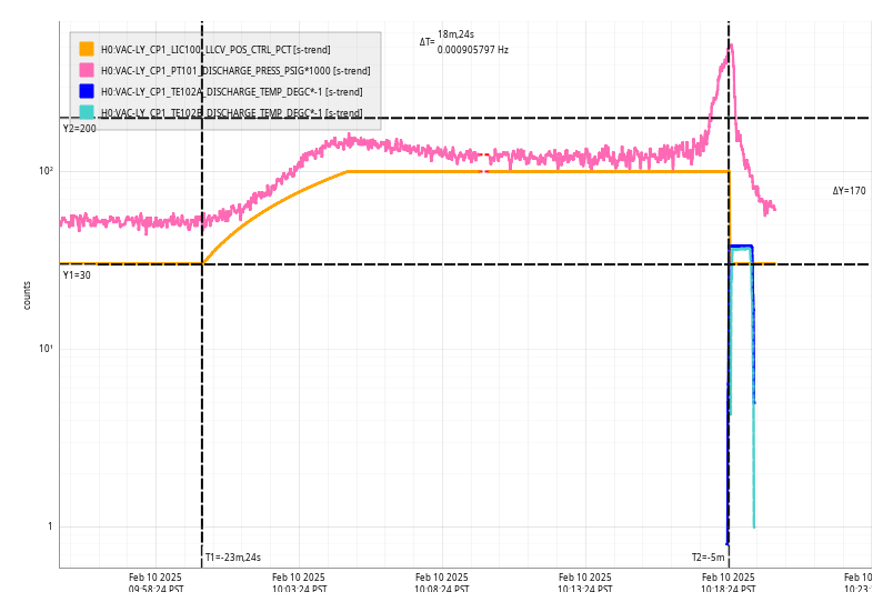
Mon Feb 10 10:18:24 2025 INFO: Fill completed in 18min 21secs
Gerardo confirmed a good fill curbside. TCmins [-38C, -37C] OAT (-3C, 26F) DeltaTempTime 10:18:24
The lock loss occurred during commissioning time but no activity was going on at the time.
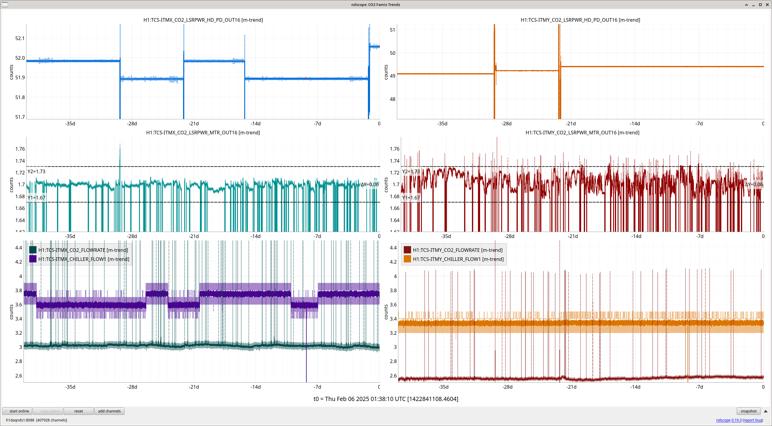
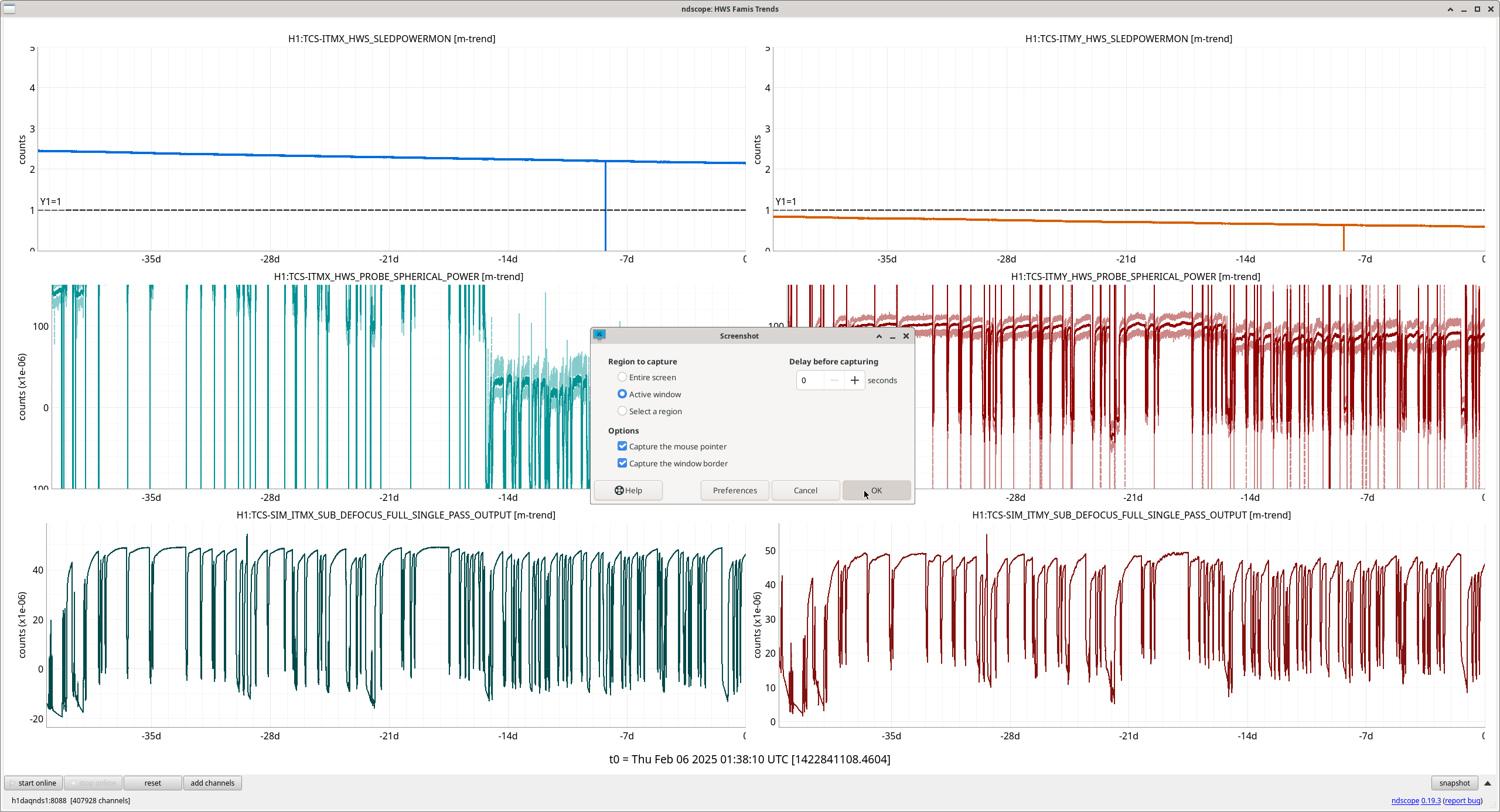
Attached are monthly TCS trends for CO2 and HWS lasers. (FAMIS link)
Whoops! Forgot to attach the actual trends!! (thanks for catching this, Camilla!) Attachements are now attached!
Sheila and I are continuing to check various PD calibrations (82260). Today we checked the POP A LF calibration.
Currently there is a filter labeled "to_uW" that is a gain of 4.015. After some searching, Sheila tracked this to an alog by Kiwamu, 13905, with [cnts/W] = 0.76 [A/W] x 200 [Ohm] x 216 / 40 [cnts/V]. Invert this number and multiply by 1e6 to get uW/ct.
Trusting our recalibration of IM4 trans, we have 56.6 W incident on PRM. We trust our PRG is about 50 at this time, so 2.83 kW are in the PRC. PR2 transmission is 229 ppm (see galaxy optics page). Then, the HAM1 splitter is 5.4% to POP (see logs like 63523, 63625). So we expect 34 mW on POP. At this time, there was about 30.5 mW measured on POP according to Kiwamu's calibration.
I have added another filter to the POP_A_LF bank called "to_W_PRC", that should calibrate the readout of this PD to Watts of power in the PRC.
POP_A_LF = T_PR2 * T_M12 * PRC_W, and T_PR2 is 229 ppm and T_M12 is 0.054. I also added a gain of 1e-6 since FM10 calibrates to uW of power on the PD.
Both FM9 (to_W_PRC) and FM10 (to_uW) should be engaged so that POP_A_LF_OUT reads out the power in the PRC.
I loaded the filter but did not engage it.
More thoughts about these calibrations!
I trended back to last Wednesday to get more exact numbers.
input power = 56.8 W
PRG = 51.3
POP A LF (Kiwamu calibration) = 30.7 mW
predicted POP A LF = 0.054 * 229 ppm * 56.8 W * 51.3 W/W = 36 mW
ratio = 30.7 mW / 36 mW = 0.852
If the above calibrations of PRG and input power are correct, we are missing about 15% of the power on POP.
During commisioning this morning, we added the final part of the ESD glitch limiting, by adding the actual limit part to ISC_LOCK. I added a limit value of 524188 to ETMX_L3_ESD_UR/UL/LL/LR filter banks, which are the upstream part of the 28 bit dac configuration for SUS ETMX. These limits are engaged in LOWNOISE_ESD_ETMX, but turned off again in PREP_FOR_LOCKING.
In LOWNOISE_ESD_ETMX I added:
log('turning on esd limits to reduce ETMX glitches')
for limits in ['UL','UR','LL','LR']:
ezca.get_LIGOFilter('SUS-ETMX_L3_ESD_%s'%limits).switch_on('LIMIT')
So if we start losing lock at this step, these lines could be commented out. The limit turn-off in PREP_FOR_LOCKING is probably benign.
Diffs have been accepted in sdf.
I think the only way to tell if this is working is to wait and see if we have fewer ETMX glitch locklosses, or if we start riding through glitches that has caused locklosses in the past.
Using the lockloss tool, we've had 115 Observe locklosses since Dec 01, 23 of those were also tagged ETM glitch, which is around 20%.
Since Feb 4th, we've had 13 locklosses from Observing, 6 of these tagged ETM_GLITCH: 02/10, 02/09, 02/09, 02/08, 02/08, 02/06.
Jim, Sheila, Oli, TJ
We are thinking about how to evaluate this change. In the meantime we made a comparison similar to Camilla's: In the 7 days since this change, we've had 13 locklosses from observing, with 7 tagged by the lockloss tool as ETM glitch (and more than that identified by operators), compare to 7 days before the change we had 19 observe locklosses of which 3 had the tag.
We will leave the change in for another week at least to get more data of what it's impact is.
I forgot to post this at the time, we took the limit turn on out of the guardian on Feb 12, with the last lock ending at 14:30 PST, so locks since that date have had the filters engaged, but since they multiply to 1, they shouldn't have an effect without the limit. We ran this scheme between Feb 3 17:40 utc until Feb 12 22:15 utc.
Camilla asked about turning this back on, I think we should do that. All that needs to be done is uncommenting out the lines (currently 5462-5464 in ISC_LOCK.py):
#log('turning on esd limits to reduce ETMX glitches')
#for limits in ['UL','UR','LL','LR']:
# ezca.get_LIGOFilter('SUS-ETMX_L3_ESD_%s'%limits).switch_on('LIMIT')
The turn off of the limit is still in one of the very early states is ISC_LOCK, so nothing beyond accepting new sdfs should be needed.
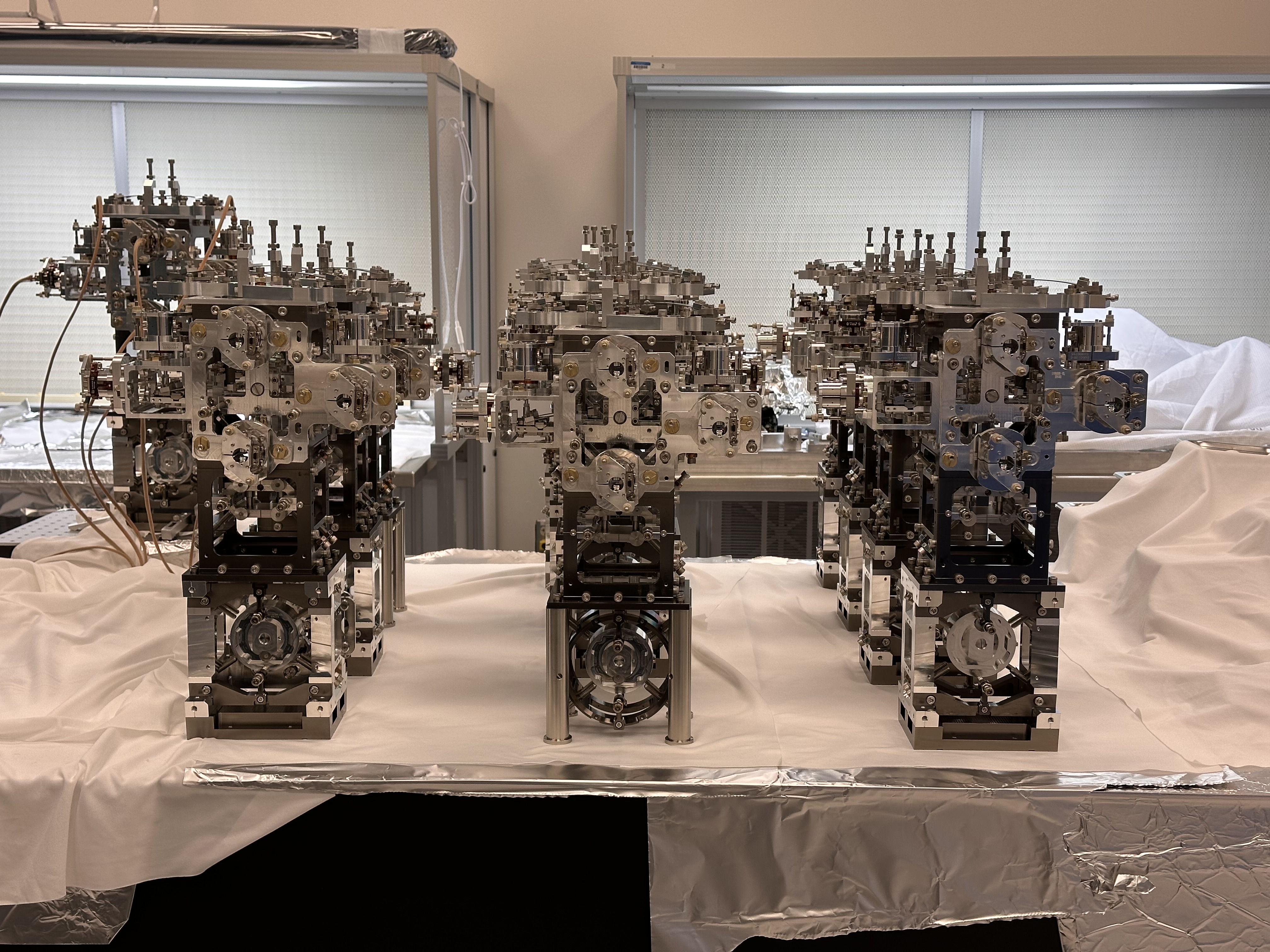
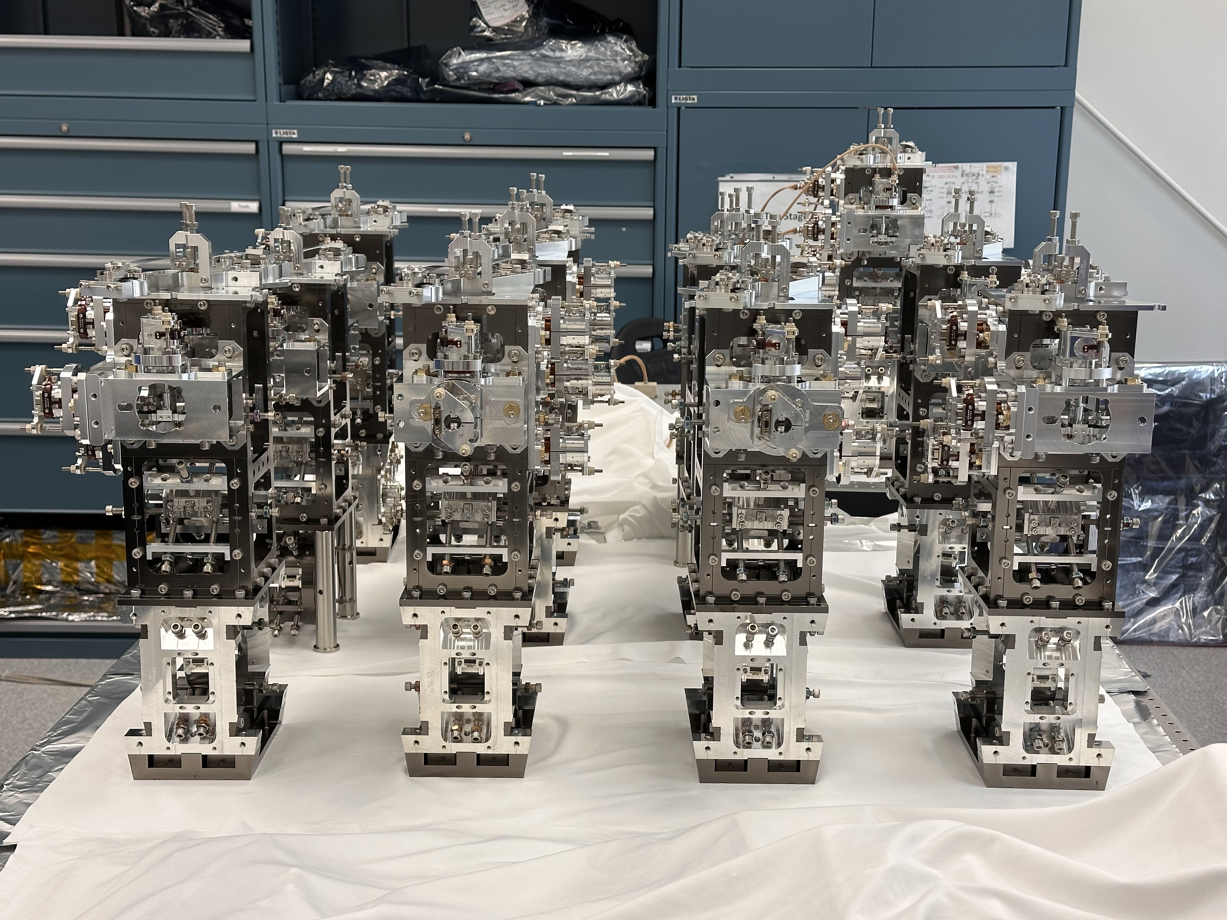
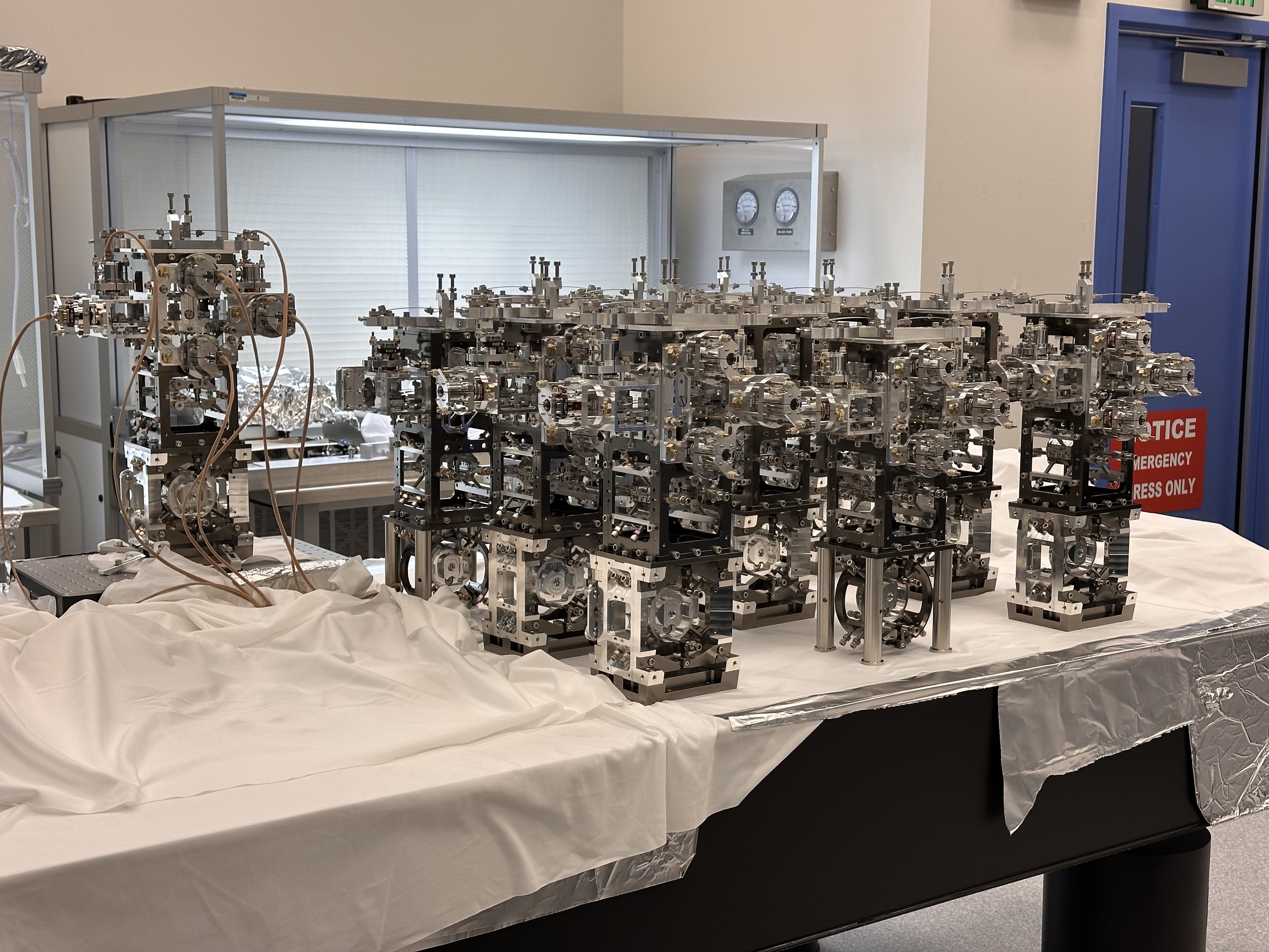
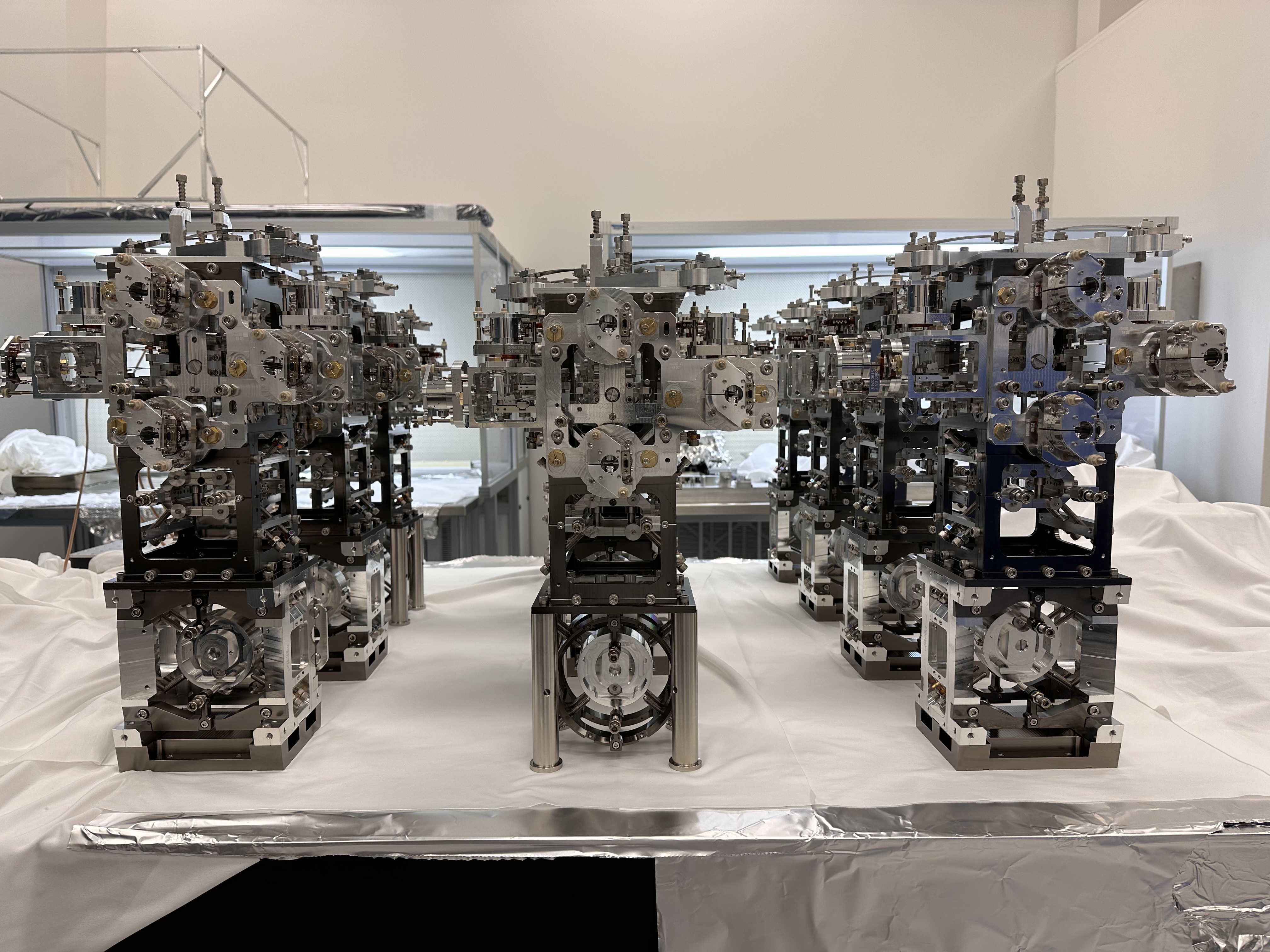
Ryan Crouch, Rahul Kumar
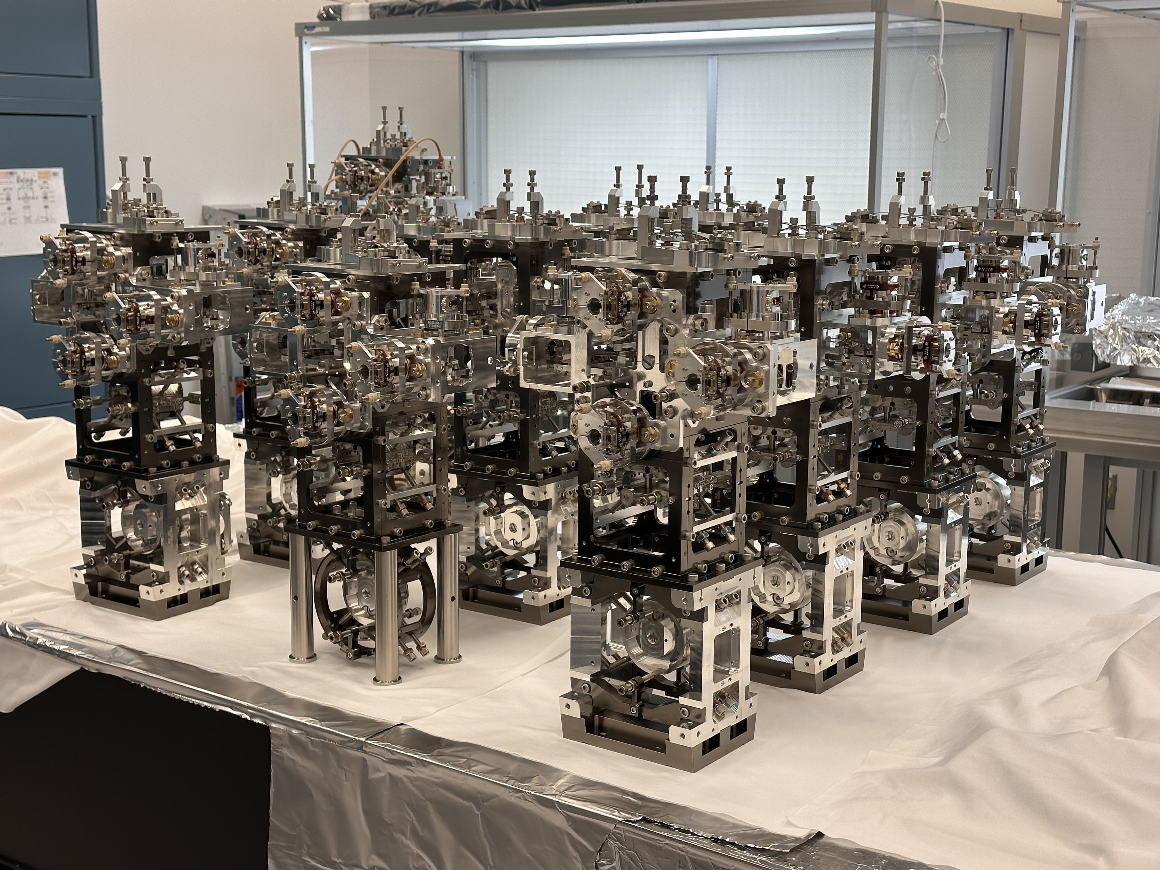
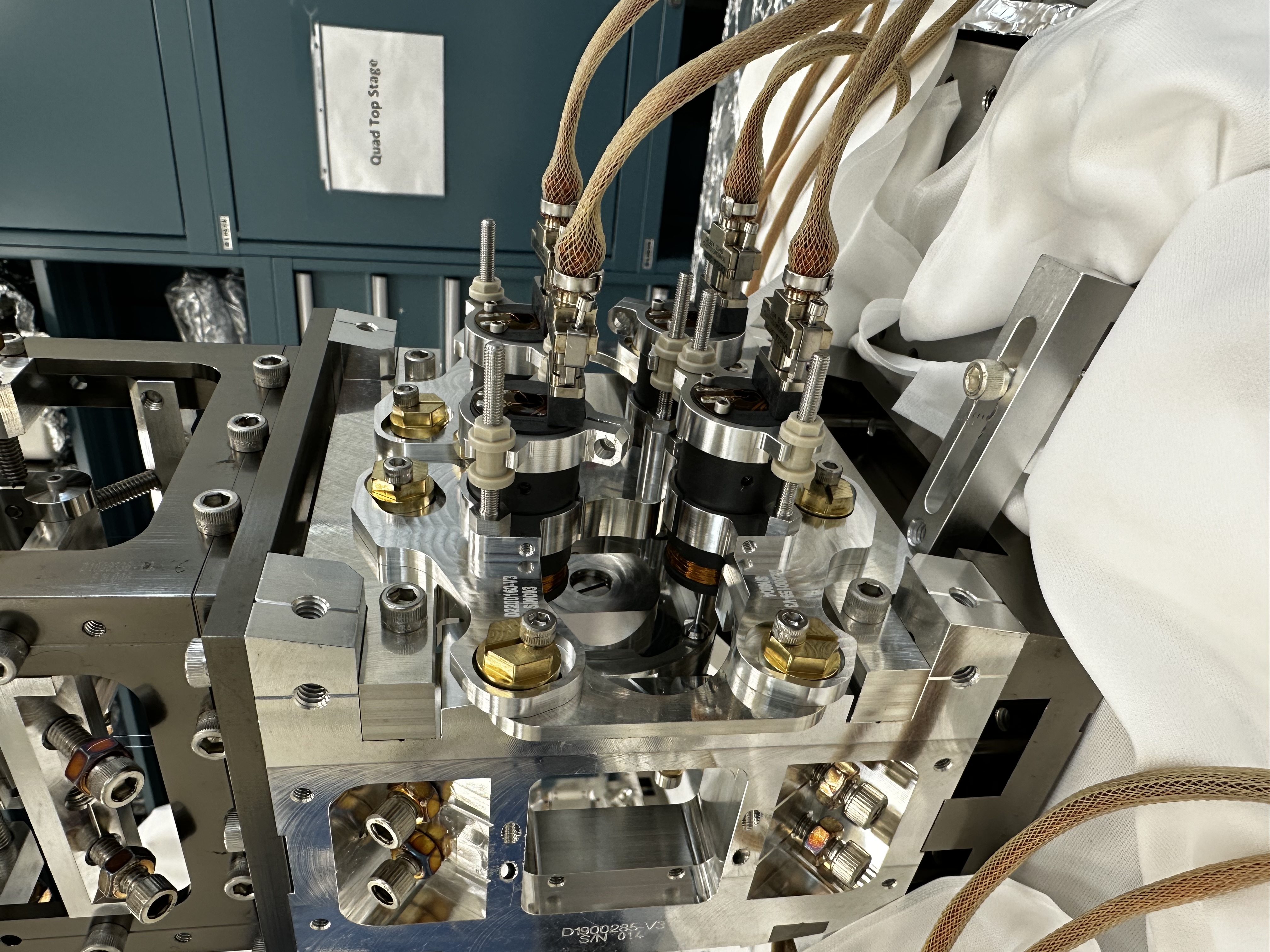
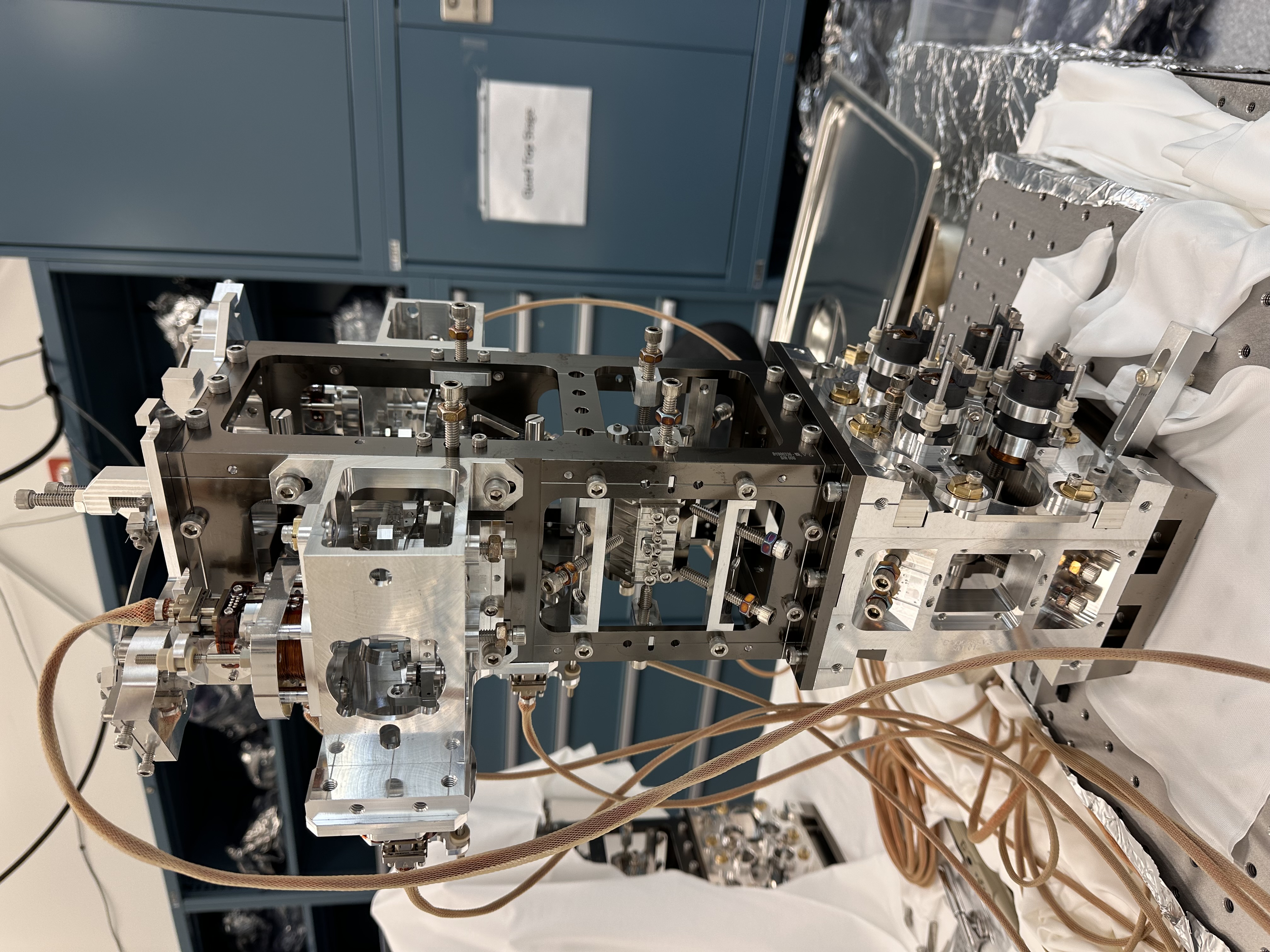
The assembly, balancing and testing of all 12 HRTS (Ham Relay Triple Suspension) for O5 is now complete. Currently all 12 HRTS has dummy optic installed at the bottom stage and once the mirrors are ready (with prisms bonded) then it will be replaced (later this year). I am attaching several pictures from the lab which shows all 12 HRTS staged on the optical bench. Later, six of the suspensions will be transported to LLO.
This plot compares the of transfer function performance of all 12 HRTS for all 6 degrees of freedom. We are still analyzing this data and there is scope for improving a couple of them (especially highlighted in green trace). Sometimes, it is as simple as adjusting the flag position wrt to LED/PD in bosems, and other times further fine tuning the balance and alignment of the blade springs.
The final two HRTS which were assembled by us are of OM0 configuration. This has bottom mass (M3 stage) actuation using AOSEM standoff assembly (as per D2300180_v2) as shows in the picture over here. The magnets used at M3 stage is 2.0 mm D x 0.5 mm T, SmCo. The transfer function results for both the OM0 configurations are as follows - attachment01 and attachment02. Both of them look healthy, when compared with the model.
Given below are the OLC, offsets and gains of the bosems attached to OM0 sn02,
| s/n 622 31669 | 15834 | 0.947 |
| s/n 639 32414 | 16207 | 0.925 |
| s/n 637 28430 | 14215 | 1.055 |
| s/n 632 27399 | 13699 | 1.094 |
| s/n 684 26138 | 13069 | 1.147 |
| s/n 698 32767 | 16383 | 0.915 |
I remeasured the associated suspension with the lime green trace (2024-9-16), a suspended version of the HRTS with structure s/n 012. Through adjusting the flags centering and position I was able to improve the measurement results, especially the verticle DOF, yaw also looks better. Previous measurement vs new measurement.
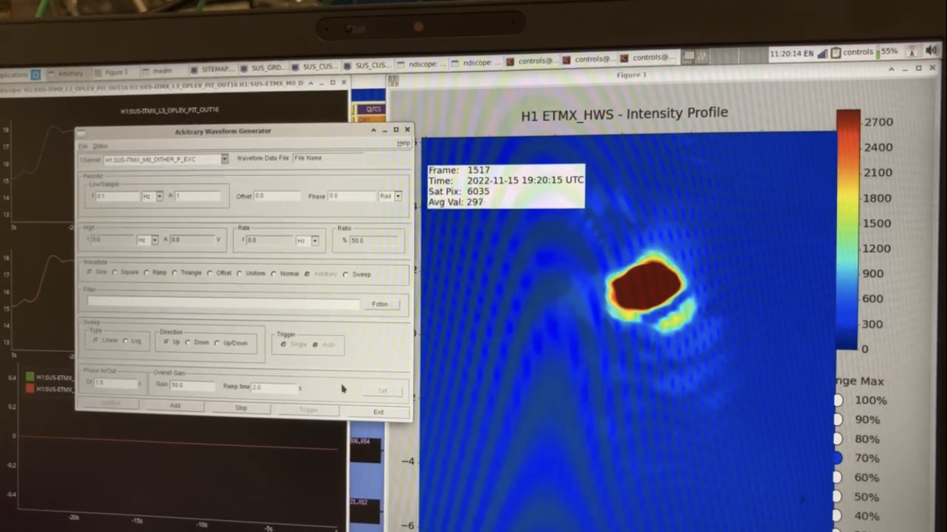
In alog 65804 Ross, Mitchell and I adjusted and dithered ITMX to see how much reflection off the ITM the ETM Hartmann sees. See attached for the ETMX HWS beam refected off the ITMX. This is a known issue in both ETM HWSs. It may explain why ETM ring heater tests look okay but not powerups.

Re-calculating for current 530nm M530F2 HWS beams, you can clearly see why the retrofections off the ITM are less of an issue with the 530nm source.
Using spec sheets C1103238 for ETM and C1103261 for ITM.
