david.barker@LIGO.ORG - posted 11:50, Friday 24 July 2026 (91234)
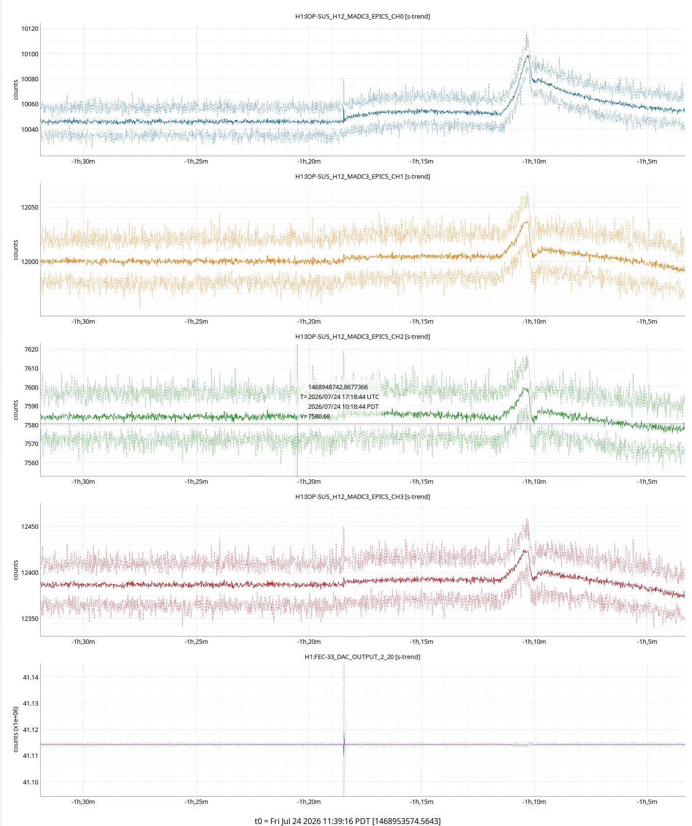
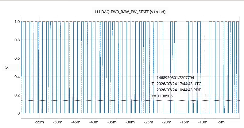
JM1 jump at 10:30
Images attached to this report
Tony, Dave:
At 10:33 FW went unstable, restarting itself after writing a new frames.
I restarted the daqd process at 10:44 (systemctl restart rts-daqd) which so far appears to have fixed it.
J. Kissel

Seeing the "first light," calibrated SPI Optical Lever amplitude spectral densities in  and , and thinking about ADC noise limitations and the calibration models assumption that the spots are centered on the QPDs drove me to re-check the spot positions on the QPDs.

Timeline of centering:
    2026-07-17 17:00 UTC (LHO:91124) -- Jennie turned on the SPI laser for the first time since doors went on and the ISIs were isolated, and re-centered *only* QPDB with M_C1 (and thought she had adjusted QPDA centering with M_M1, thought she had mistakenly moved M_M2, but confirmed later she did not; LHO:91219).
    2026-07-23 14:00 UTC (LHO:91218) -- Jim unlocks and restores function of HAM2 HEPI, such that now both HAM2 and HAM3 are fully functional, and remain ISOLATED with corner station sensor correction ON as their nominal condition.
    2026-07-23 20:30 UTC (LHO:91221) -- Jennie re-centered (only) QPDB again using M_C1.
    2026-07-24 16:05 UTC (this aLOG) -- Not knowing that Jennie had yet recentered any QPDs, and finding QPDA PIT's normalized beam displacement at +0.23 [rad], I recentered *both* QPDA and QPDB.

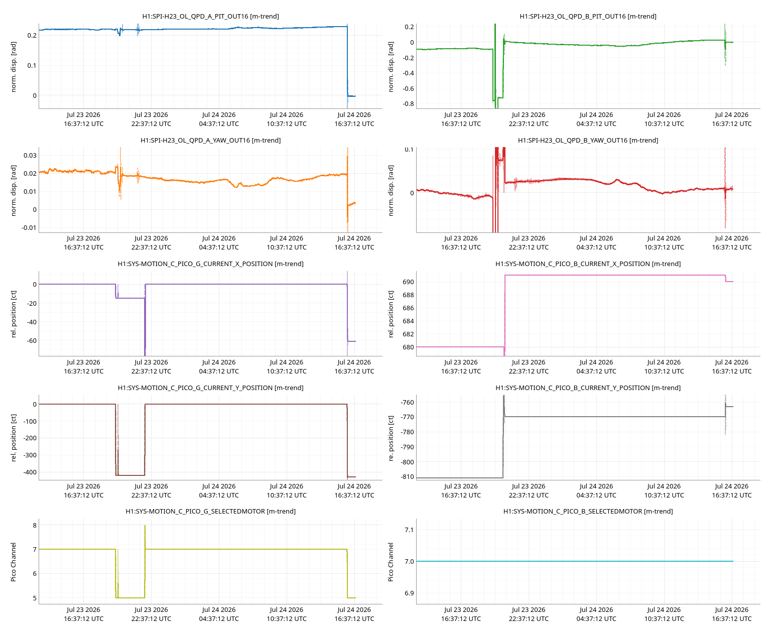
I attach a similar trend of relevant channels including both Jennie's centering work from 2026-07-23 and mine this morning. Similar to Jennie's plots but with thick lines, light mode, and with the y-axes labeled.
I saved this template to
    /opt/rtcds/userapps/release/spi/h1/ndscope/QPD_Centering.yaml  (rev 35598).


Here're the DC values of the QPDs after this morning's centering (done with the precision one can achieve with a picomotor STEP SIZE of 1 [ct]):
$ gpstime now;z avg -30 H1:SPI-H23_OL_QPD_A_PIT_OUT_DQ H1:SPI-H23_OL_QPD_A_YAW_OUT_DQ H1:SPI-H23_OL_QPD_B_PIT_OUT_DQ H1:SPI-H23_OL_QPD_B_YAW_OUT_DQ -s

t =
PDT: 2026-07-24 09:27:44.113664 PDT
UTC: 2026-07-24 16:27:44.113664 UTC
GPS: 1468945682.113664

Channel                        t-30 sec average       t-30 standard deviation
H1:SPI-H23_OL_QPD_A_PIT_OUT_DQ -0.0024822048842906954 4.722167842008142e-06
H1:SPI-H23_OL_QPD_A_YAW_OUT_DQ  0.0030039884615689514 5.884913671432033e-06
H1:SPI-H23_OL_QPD_B_PIT_OUT_DQ -0.0022898733150213957 8.094109742945136e-05
H1:SPI-H23_OL_QPD_B_YAW_OUT_DQ  0.008859152471025783  4.6337990240392655e-05

$ gpstime now;z avg -30 -s H1:SPI-H23_OL_QPD_A_PIT_OUT_DQ H1:SPI-H23_OL_QPD_A_YAW_OUT_DQ H1:SPI-H23_OL_QPD_B_PIT_OUT_DQ H1:SPI-H23_OL_QPD_B_YAW_OUT_DQ H1:SPI-H23_OL_QPD_A_SUM_OUT16 H1:SPI-H23_OL_QPD_B_SUM_OUT16

t0 =
PDT: 2026-07-24 09:54:54.983607 PDT
UTC: 2026-07-24 16:54:54.983607 UTC
GPS: 1468947312.983607

Channel                        (t0-30 sec) average       (t0-30 sec) standard deviation
H1:SPI-H23_OL_QPD_A_PIT_OUT_DQ  -0.002713  3.4e-05
H1:SPI-H23_OL_QPD_A_YAW_OUT_DQ   0.003265  4.2e-05
H1:SPI-H23_OL_QPD_B_PIT_OUT_DQ  -0.002033 10.0e-05
H1:SPI-H23_OL_QPD_B_YAW_OUT_DQ   0.009682 5.3e-05
H1:SPI-H23_OL_QPD_A_SUM_OUT16   25.846691 0.003820814636259141
H1:SPI-H23_OL_QPD_B_SUM_OUT16   29.265472 0.004081774857250754
WP13433 TW1 offload
As Tony mentioned, I did a quick NDS1 restart at 07:57 to get it to serve the past 6 months of minute trends from the archive following this week's copy.
At 08:09 I started the deletion of the old data from TW1's SSD-RAID. This typically takes a few hours. At the start of deletion disk usage was 93%.
File deletion completed at 10:10 (took 2hr01min). WP13433 has been closed.
TITLE: 07/24 Day Shift: 1430-2330 UTC (0730-1630 PST), all times posted in UTC
STATE of H1: Planned Engineering
OUTGOING OPERATOR: None
CURRENT ENVIRONMENT:
SEI_ENV state: CALM
Wind: 5mph Gusts, 2mph 3min avg
Primary useism: 0.02 μm/s
Secondary useism: 0.10 μm/s
QUICK SUMMARY:
The Vacuum pressure is still being pumped down.
CDS team needed to reboot the NDS server again so the NDScope screen shots may stop beifly.
SUS: First stage of PRM seems to be pushing a bit harder than I'd expect given that it's misaligned.
Restarting some stuck IOCs:
MX weather station has been down since the power outage Thu16jul2026. This runs as a containerized IOC on the service host cluster. I restarted its PCS resource, it is running again.
The CDS Rack Smart Power Strip IOC has been down for a few days. It runs as a systemd service on cdsioc0. I restarted pwr_strip_ioc.service, it is running again.
Jeff, Sheila, Fil, Elenna, Oli
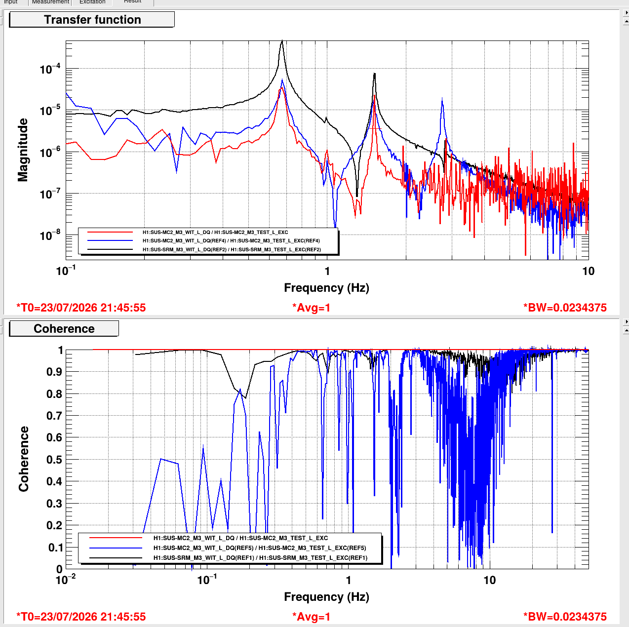
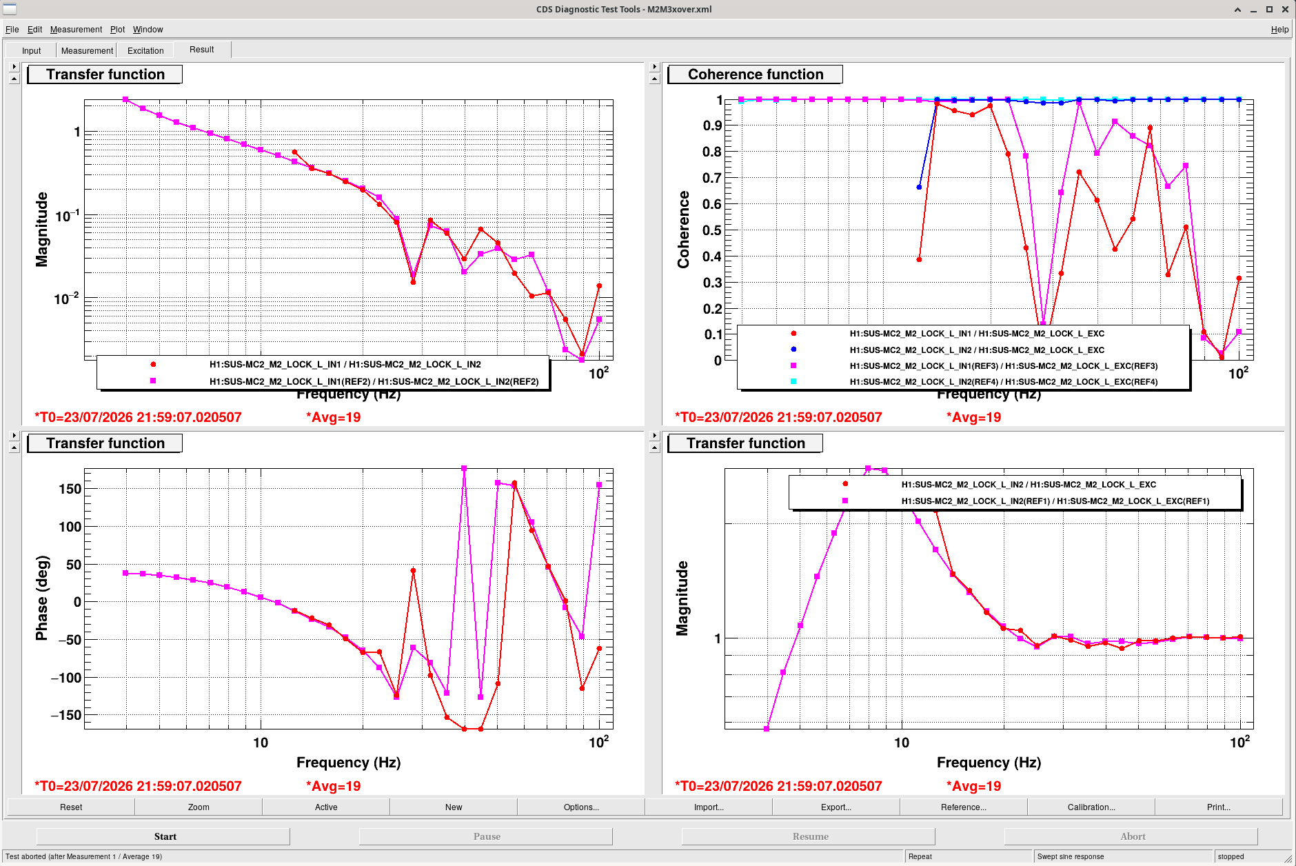
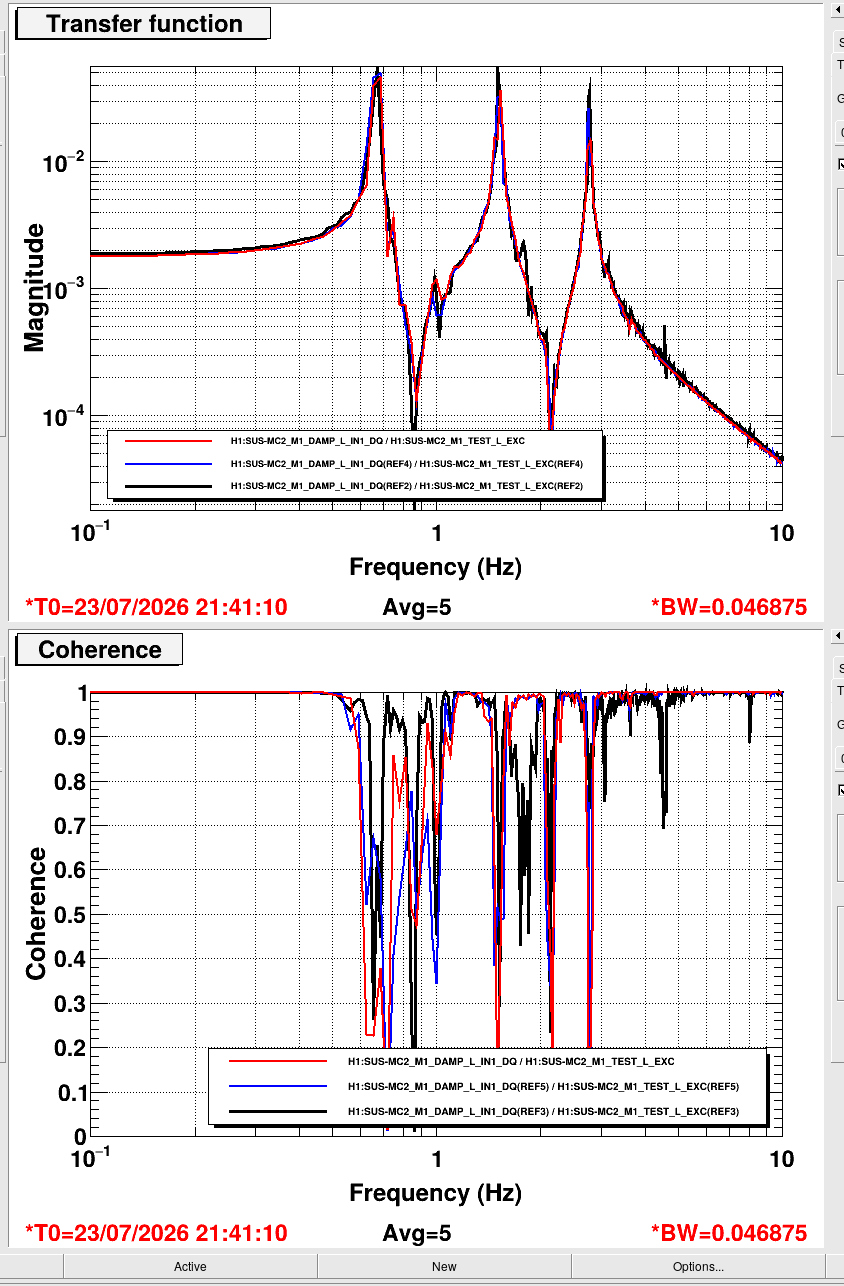
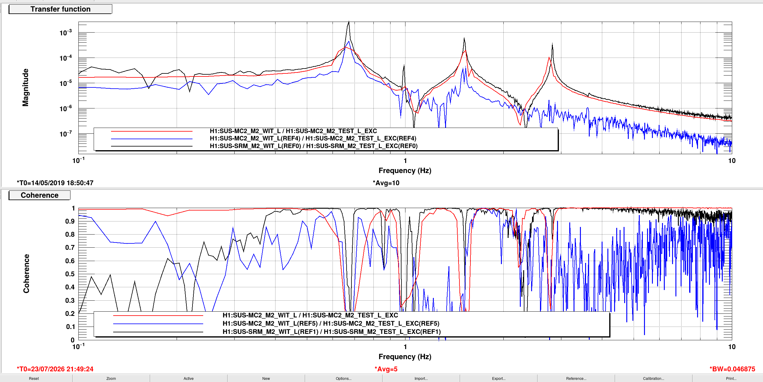
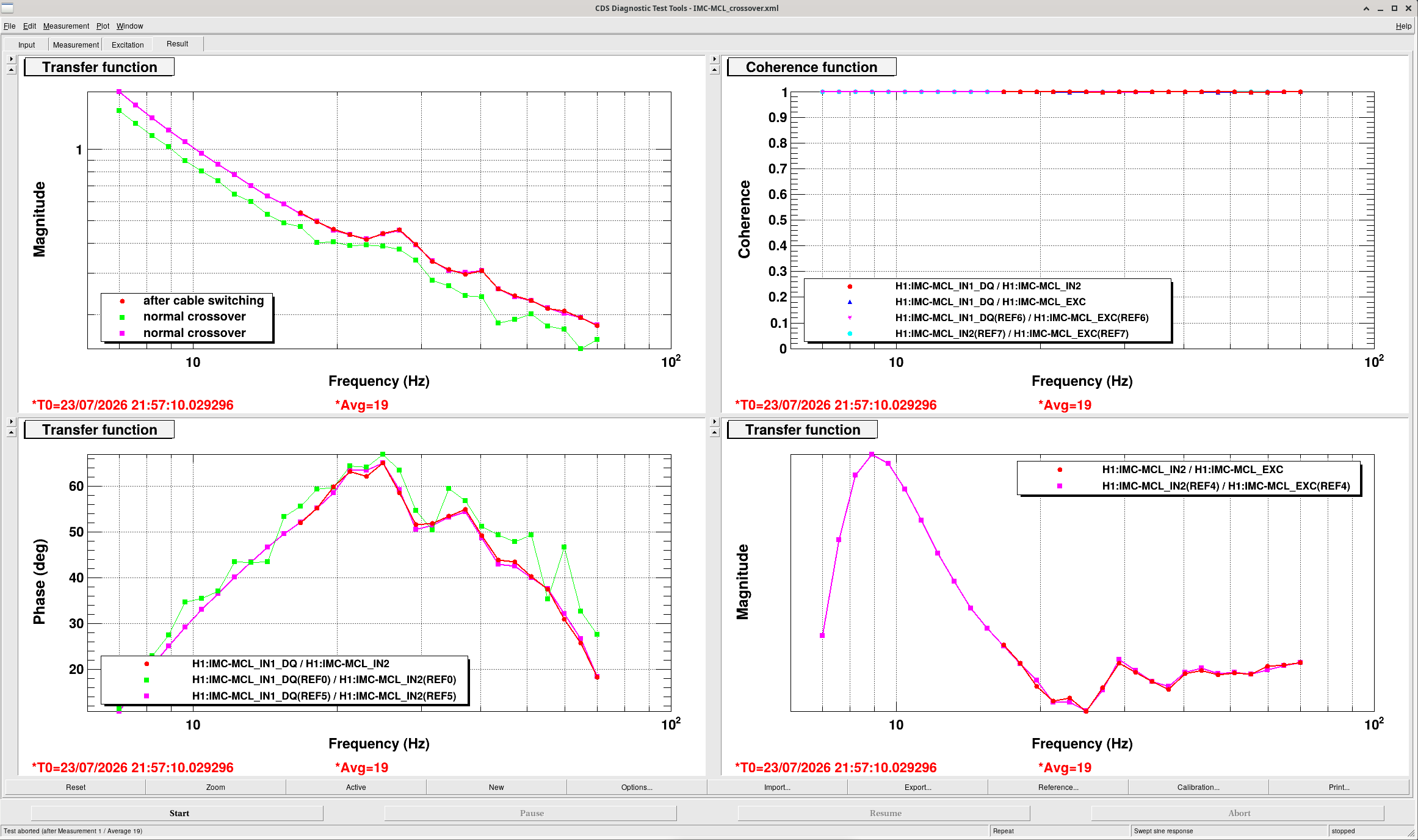
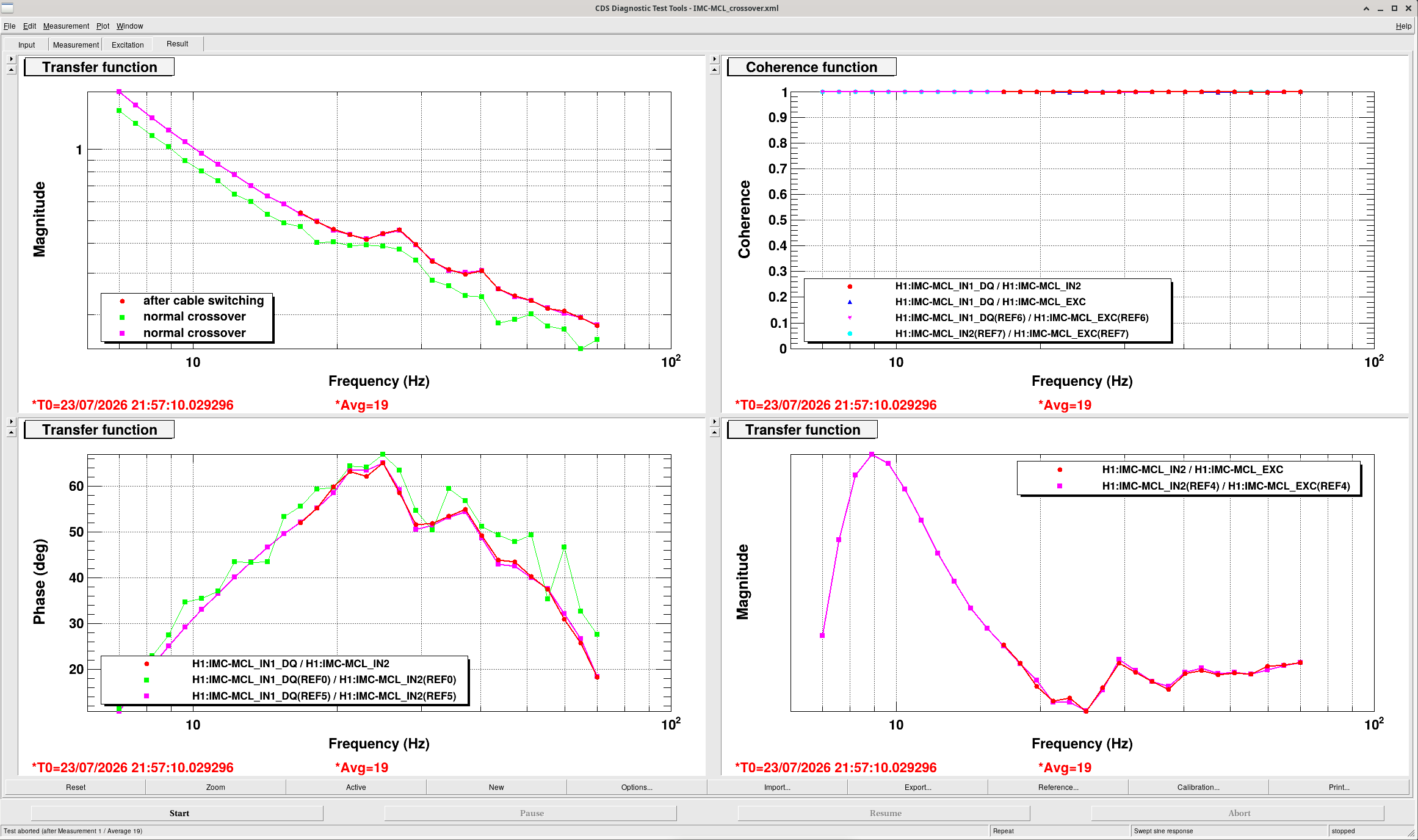
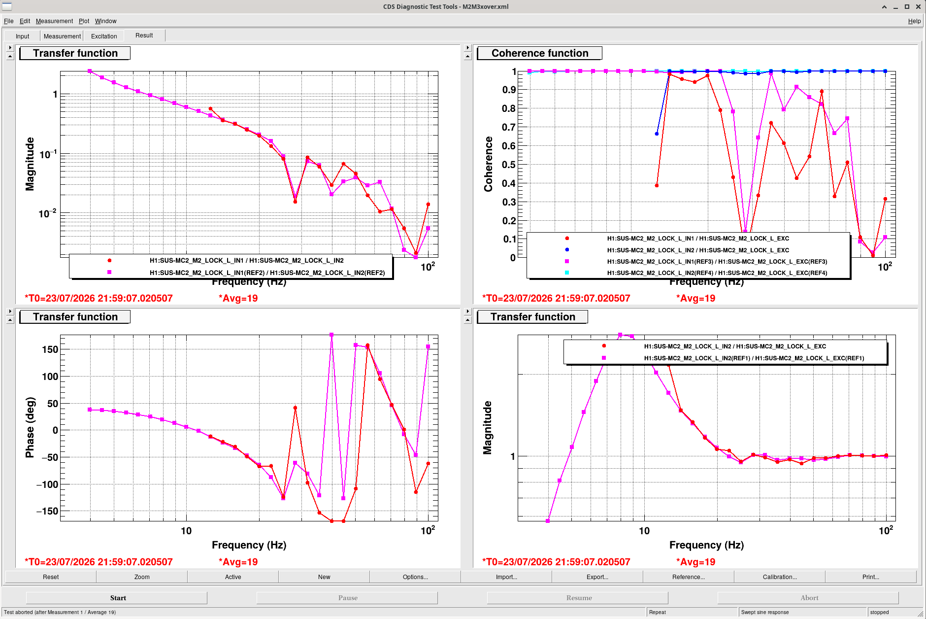
The feedthrough cables (air side) for MC2 M2 and M3 have been swapped and now MC2 is back to behaving how we expect it to. Transfer functions for M1 to M1, M2 to M2, and M3 to M3 are correct (red traces) and crossover plots for MCL and M2/M3 are looking good.
Current correct cable numbering for MC2 at the HAM3 D6 feedthrough port is:
D6-F1 -> MC2 M3 (HAM3_020)
D6-F2 -> MC2 M1 (HAM3_001)
D6-F3 -> MC2 M2 (HAM3_019)
This should be updated in the flange layout D1002874, which I don't see the altium file for. Next time we open up HAM3, we should fix this lineup so F1/F2/F3 line up with MC2 M1/M2/M3.
Full troubleshooting:
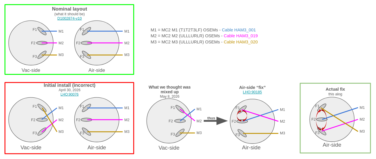
After lots of troubleshooting and my MC2 M2 and M3 measurements from yesterday, Jeff noted that the M2 to M2 TFs looked a lot like the M3 to M3 Tfs, and vice versa. This was also very suspicious because back in May (90185) there had been a feedthrough swap for the feedthrough that MC2's M1 (T1/T2/T3/LF), M2, and M3 were all connected to, and M1 and (we thought) M2 had been found to be plugged in incorrectly on the vac side. After the plugs going into F1 and F2 had been swapped, we had measured only M1 to confirm that the swap was successful.
A (silly) mistake:
Fil and I went out to HAM3 D6 flange and meant to swap the M2 and M3 cables, but since the flange layout was still listing F1 -> M1, F2 -> M2, F3 -> M3, we swapped the cables connected to F2 and F3, which were actually M1 and M3, respectively. We determined that this was wrong because M1 to M1 and M3 to M3 looked horrible but M2 to M2 looked the same as before (wrong but not different), which means that M2 must have been in the F1 port and so hadn't actually been swapped with M3. We noticed later that this lineup was written in the May 8th MC2 'fix' alog(90185).
Actual fix:
We plugged M3 (HAM3_020) into F1, M1 (HAM3_001) into F2, and M2 (HAM3_019) into F3. Here's a diagram/timeline of this mistake and fixing it.
Everything is looking good for MC2 and it seems like we've been able to go back to using MC2 to lock the IMC normally.
I'll add plots next week comparing MC2 M2 to SRM M3 and vice versa


Jennie W
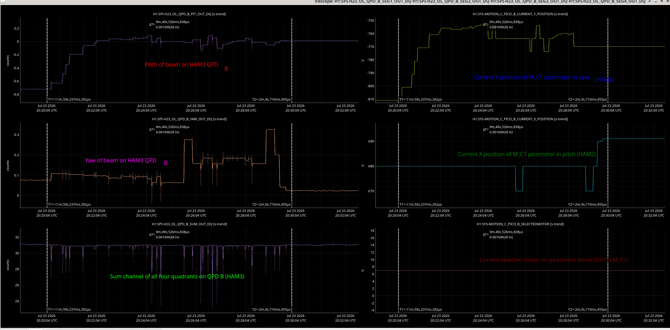
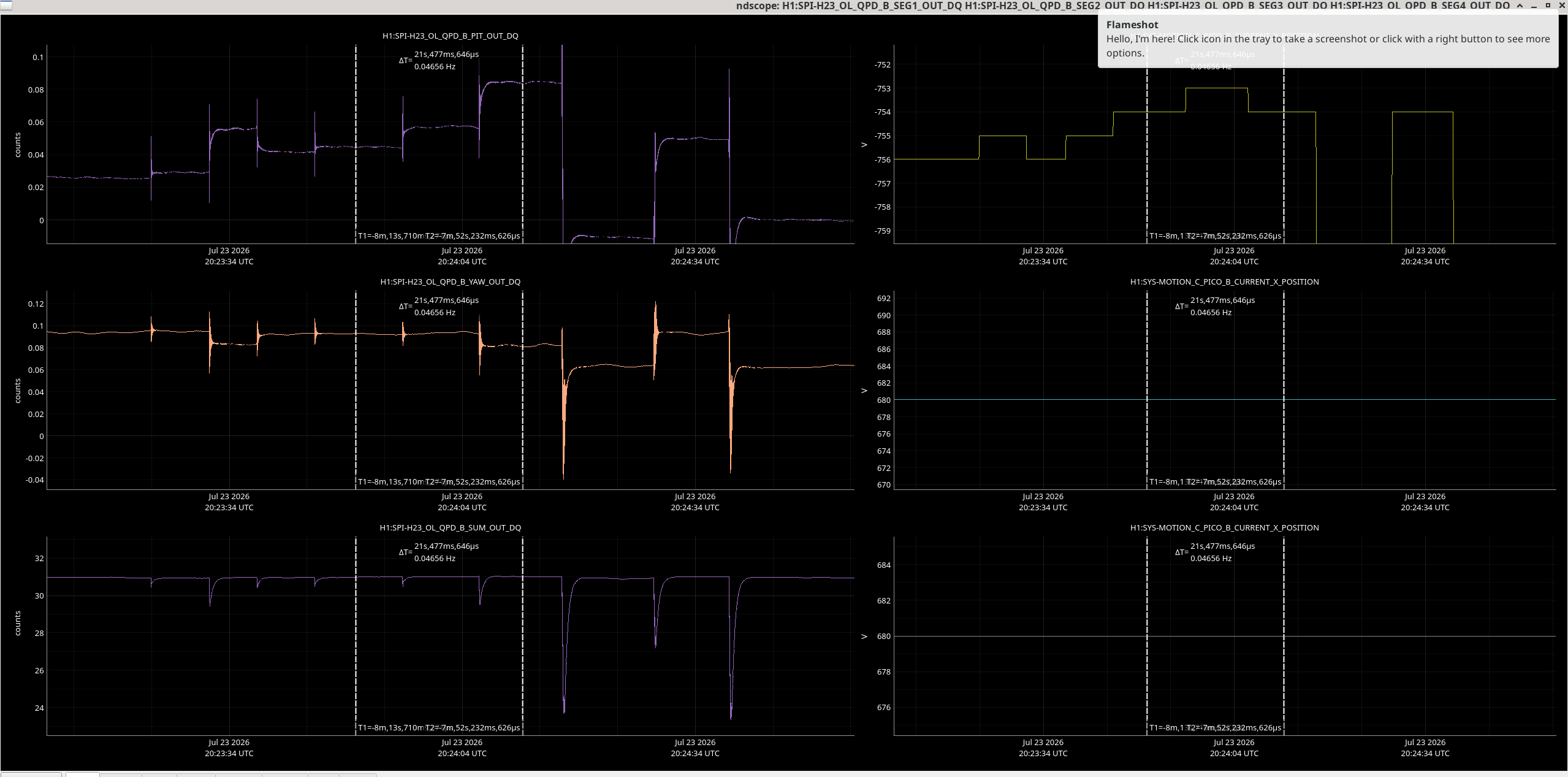
Today after verifying I didn't need to do any alignment on ISIK itself (SPI bench on HAM3), I used the picomotor on HAM2 (M_C1) to align the beam to the QPD B which resides on ISIK.
I have attached a labelled ndscope showing which channels to look at while changing the M_C1 picomotor.
The yaml files for aligning QPDA and B are saved as QPBa_picos.yaml and QPDB_picos.yaml in userapps/spi/h1/ndscope.
One weird thing I noticed while moving the picomotors is that while moving in small steps of 1 count (speed of the picomotor was set to 'jog' which is 50 Hz), the beam would move in the same direction on the QPD while I change direction on the picomotor.
See an example in this image.
Not sure why this happened as it was not a problem when using larger steps of 10 counts on the picomotor.
With steps of 10 counts the beam goes down in pitch on QPDB which corresponds to down on picomotor controls (channel Y down on picomotor controller).
To go up in yaw on QPD B you need to go right on picomotor controls (channel X up in magnitude).
Summary: QPD A and B are fairly well centred when HAM 2 and 3 are isolated now.

Jennie W
Summary: I didn't move M_M2 picomotor on Friday 17th July.
Last Friday (LHO alog #91124) I centred the QPDB on HAM3 spi bench using M_C1 picomotor (picomotor B ch7 which is controller 5) on HAM2.
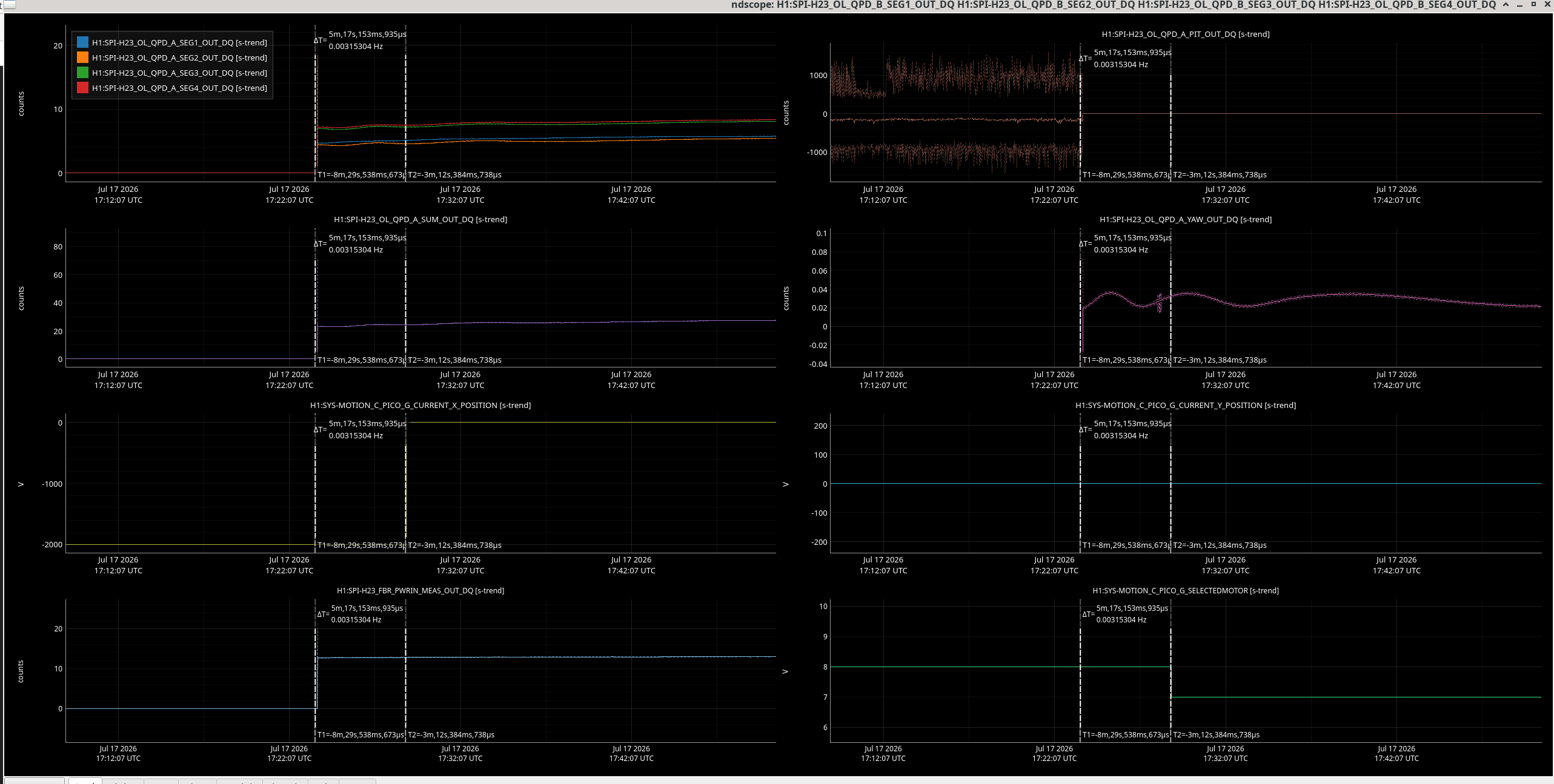
I wrote the log the week after and checking back in the H1:SYS-MOTION_C_PICO_G_CURRENT_X_POSITION I thought I had also moved M_M2 (CH7) on picomotor driver G.
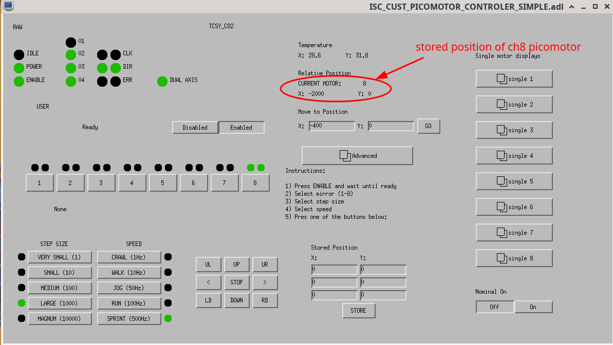
Checking back it turns out the 2000 count jump I was seeing was just the 2000 count difference between the values stored for ch8 and ch7 when I switched the selected motor to channel 7.
See the ndscope picture where the second cursor shows when the green channel H1:SYS-MOTION_C_PICO_B_SELECTEDMOTOR changed from 8 to 7 and you can see that the the yellow channel H1:SYS-MOTION_C_PICO_B_CURRENT_X_POSITION changed up by 2000 counts.
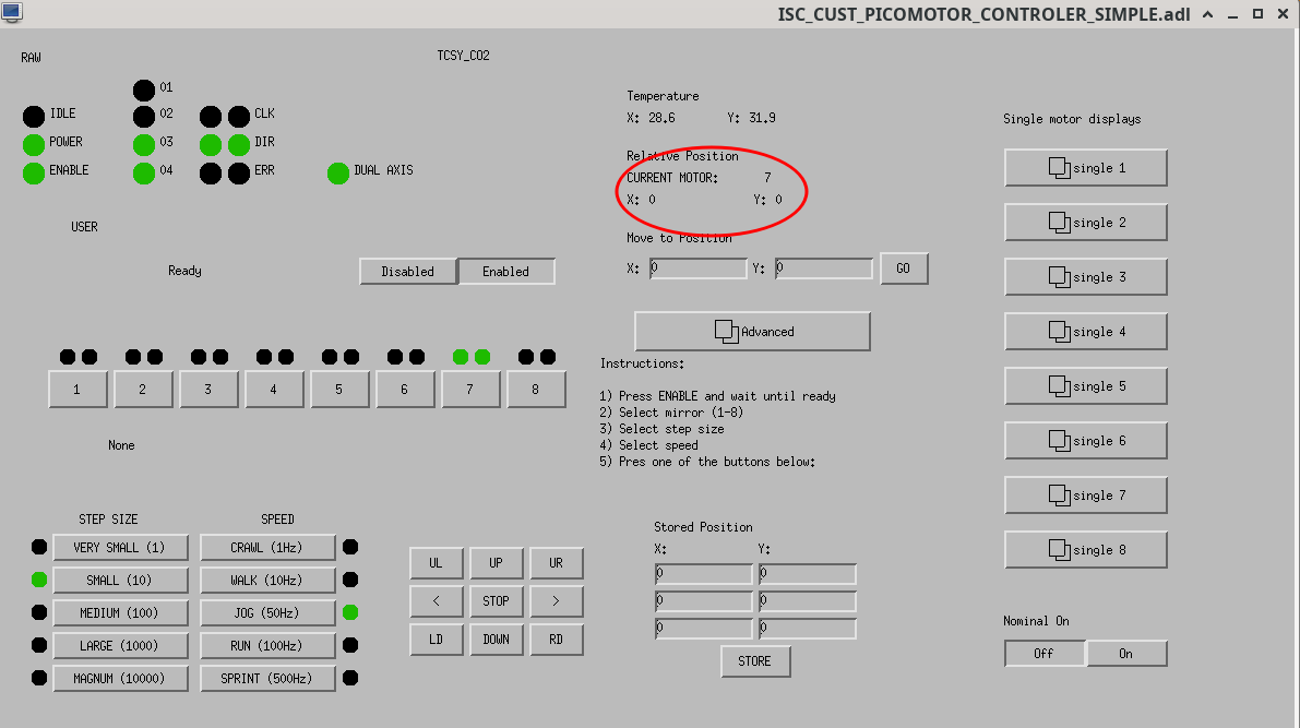
Looking at the Beckhoof screen you can see that when ch8 is selected this stored value (-2000) appears on the screen and is not there when ch7 is selected. I mistakenly thought these were reset when the selected motor was changed.
So no re-alignment of M_M2 is needed.
TITLE: 07/23 Day Shift: 1430-2330 UTC (0730-1630 PST), all times posted in UTC
STATE of H1: Planned Engineering
INCOMING OPERATOR: Ibrahim
SHIFT SUMMARY: Good progress today towards DRMI, see commissioning notes in alog91211. HEPI was unlocked for HAMs 1 & 2; see alog91218. Dust alarms throughout the day in the LVEA and optics lab. The LVEA remains Laser HAZARD and corner volumes are still pumping down.
LOG:
| Start Time | System | Name | Location | Lazer_Haz | Task | Time End |
|---|---|---|---|---|---|---|
| 14:41 | FAC | Kim, Dawn | LVEA, OptLab | - | Technical cleaning | 15:31 |
| 15:27 | VAC | Jordan | MY | - | Reset pump | 15:53 |
| 15:57 | FAC | Kim | LVEA | - | Technical cleaning | 16:27 |
| 16:26 | SPI | Jennie | LVEA | - | Checking electronics in SUS rack | 17:37 |
| 16:28 | FAC | Kim | MX | - | Technical cleaning | 17:29 |
| 16:35 | ISC | Sheila | LVEA | Y | ISCT1 alignment | 17:09 |
| 17:04 | TCS | Camilla | OptLab | - | Looking for camera cans | 17:20 |
| 17:20 | VAC | Jordan | LVEA | - | Cleanup by CP1 | 18:53 |
| 18:02 | SPI | Jennie | LVEA | - | Checking electronics in SUS rack | 18:26 |
| 18:06 | TCS | Camilla, TJ | LVEA | - | Attaching camera cans | 18:58 |
| 18:51 | ISC | Sheila | LVEA | Y | ISCT1 alignment | 19:08 |
| 19:03 | TCS | Camilla, Jackie | PrepLab | - | CHETA work | 19:37 |
| 19:26 | SEI | Jim | LVEA | - | Unlocking HEPI, BSC2 tests | 20:03 |
| 20:46 | CDS | Fil | LVEA | - | Terminating cables | 21:40 |
| 21:14 | SUS | Oli | LVEA | - | MC2 cable swaps | 21:40 |
| 21:24 | TCS | Camilla | PrepLab | - | Checking cables | 21:41 |
| 21:34 | VAC | Jordan, Gerardo | EY | - | Prepping for pump swap | Ongoing |
Continued work on DRMI - nothing further to add.
JAC_HEATER Guardian is off. IMC is offline. IFO is open to anyone who wants to take measurements.
| Start Time | System | Name | Location | Lazer_Haz | Task | Time End |
|---|---|---|---|---|---|---|
| 14:41 | FAC | Kim, Dawn | LVEA, OptLab | - | Technical cleaning | 15:31 |
| 15:27 | VAC | Jordan | MY | - | Reset pump | 15:53 |
| 15:57 | FAC | Kim | LVEA | - | Technical cleaning | 16:27 |
| 16:26 | SPI | Jennie | LVEA | - | Checking electronics in SUS rack | 17:37 |
| 16:28 | FAC | Kim | MX | - | Technical cleaning | 17:29 |
| 16:35 | ISC | Sheila | LVEA | Y | ISCT1 alignment | 17:09 |
| 17:04 | TCS | Camilla | OptLab | - | Looking for camera cans | 17:20 |
| 17:20 | VAC | Jordan | LVEA | - | Cleanup by CP1 | 18:53 |
| 18:02 | SPI | Jennie | LVEA | - | Checking electronics in SUS rack | 18:26 |
| 18:06 | TCS | Camilla, TJ | LVEA | - | Attaching camera cans | 18:58 |
| 18:51 | ISC | Sheila | LVEA | Y | ISCT1 alignment | 19:08 |
| 19:03 | TCS | Camilla, Jackie | PrepLab | - | CHETA work | 19:37 |
| 19:26 | SEI | Jim | LVEA | - | Unlocking HEPI, BSC2 tests | 20:03 |
| 20:46 | CDS | Fil | LVEA | - | Terminating cables | 21:40 |
| 21:14 | SUS | Oli | LVEA | - | MC2 cable swaps | 21:40 |
| 21:24 | TCS | Camilla | PrepLab | - | Checking cables | 21:41 |
| 21:34 | VAC | Jordan, Gerardo | EY | - | Prepping for pump swap | 22:36 |
| 22:34 | TCS | Camilla | CHETA lab/ LVEA | N | Parts grab | 22:59 |
| 22:37 | VAC | Gerardo, Jordan | LVEA | YES | Checking on BSC2 pump | 23:01 |
| 22:53 | PEM | Robert, Miranda | LVEA | YES | Setting up shakers for solar farm analysis | 23:16 |
| 23:08 | SEI | Jim | LVEA | YES | Rack retrieval HAM3 | 23:14 |
| 00:04 | VAC | Jordan | MY | N | Pump closure | 00:15 |
| 00:59 | VAC | Gerardo | LVEA | YES | Picture | 01:59 |
Over lunch I went to HAM1&2 to unlock HEPI. Not much to say, stops unlocked, signs flipped, iso gains reverted to 1 and everything turned right back on. I can now try to find time to commission St0 ff for HAM2.
| POP A LF | POPAIR B LF | REFLAIR A LF | MICH IN1 (REFLAIR A 45 Q) | PRCL IN1 (REFLAIR A 9I) | POPAIR B RF18 | |
| PRMI O4 | 200-400 | 200 | 2-10 | +/-6000 | +/-600 | 80-100 |
| PRMI now | 100 | 6 | 2.5-4 | +/-20 | +/-100 | 5 |
| PRX O4 | 0.5 | |||||
| PRX now | 0.5 |
In order to fix this alignment issue, Sheila, Keita, and I had some different ideas, and it was hard to determine the best path.
Here is the one we tried:
This is the state of the alignment as I am leaving it tonight:
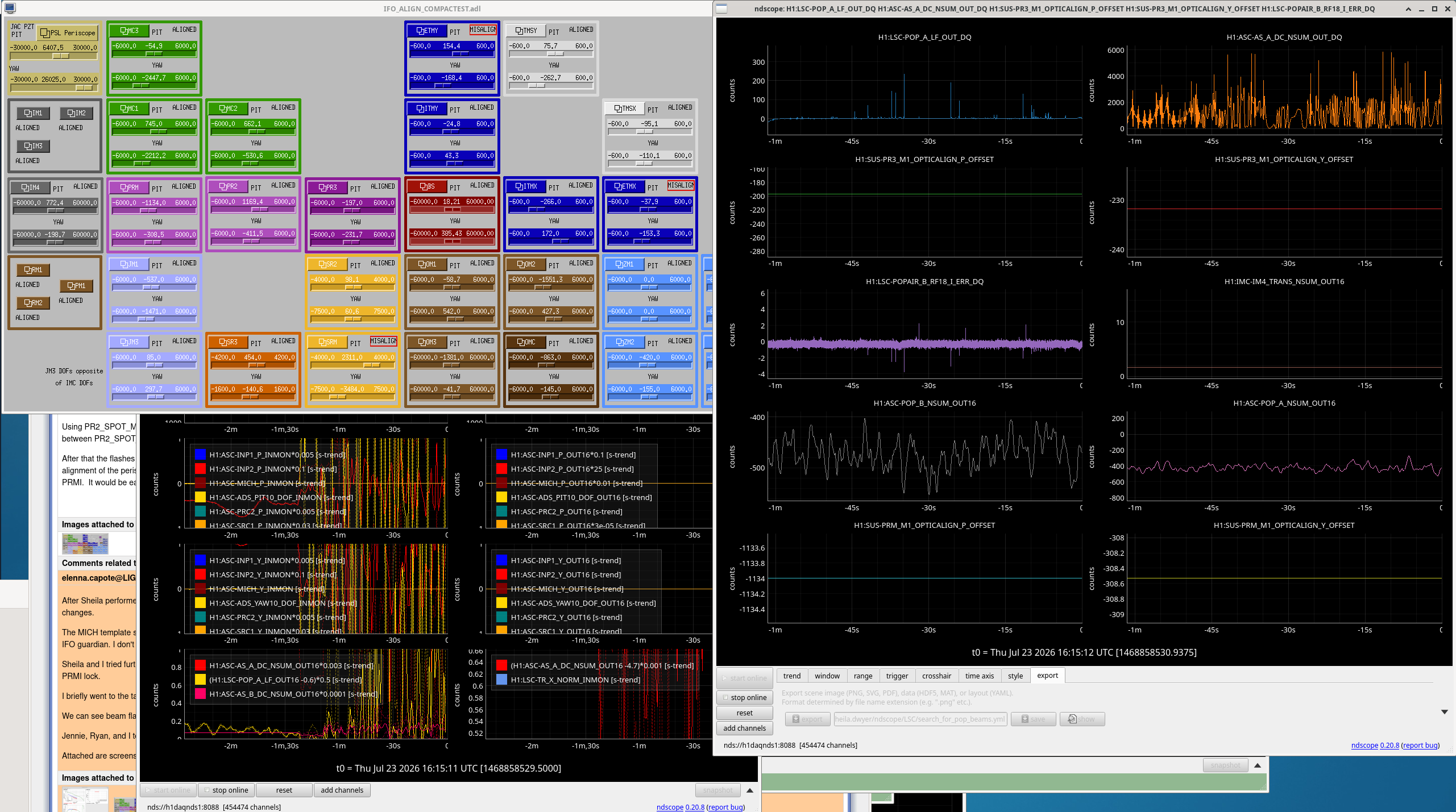
Screenshot attached of all these settings.
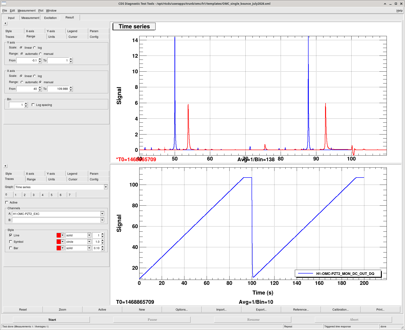
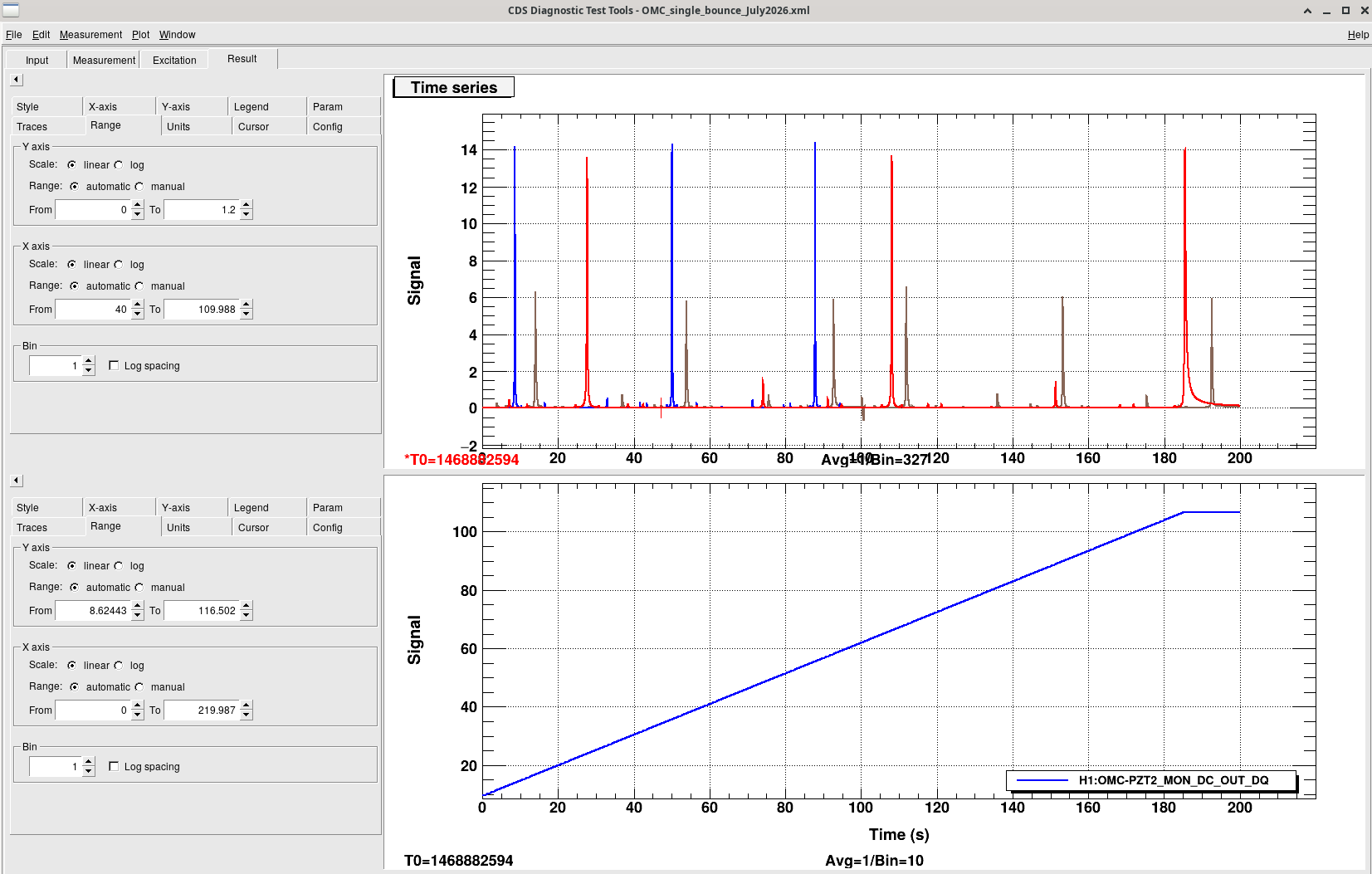
Earlier we did some OMC scans and got weird results. We tracked this down to an incorrect DCPD whitening setting. Keita fixed it, and we reran the scans, the carrier peak heights are now correct compared to the blue reference.
Oli tracked down the problem with MC2. All crossovers are fine now and the mode cleaner locks with normal gain settings. They will alog the details.
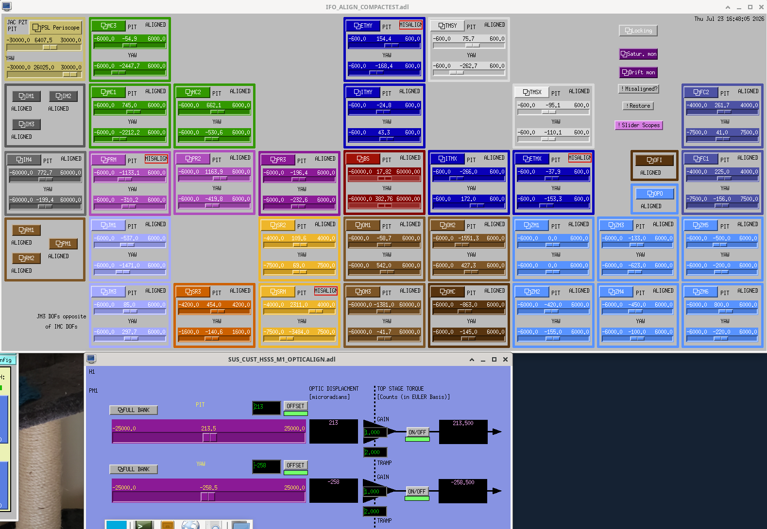
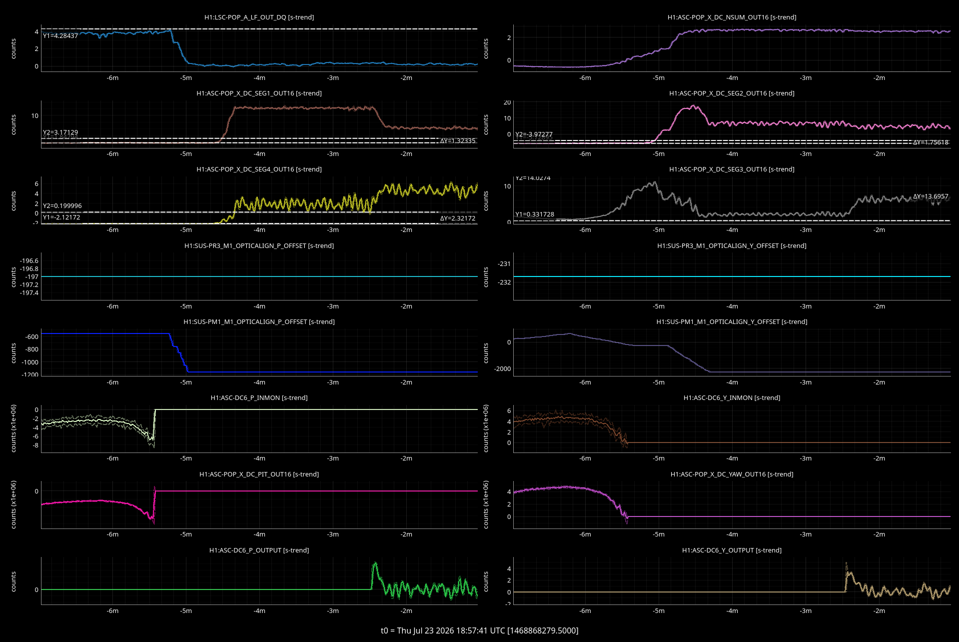
Centering on POP X DC with PM1 pulls beam off POP A LF
Right now we have an alignment that can bring the beam to both POP A in vac and to the POPAIR diodes on ISCT1 in a PRMI, or with either PRX or MICH locked.
However, the beam was very far off of POP X WFS DC, suggesting PM1 is not well-aligned. I spent a bunch of time trying to move PM1 while keeping the beam on POP A LF and improving the POP X alignment while we are locked on MICH DARK, which brings a lot of light to the POP port.
I gave up on keeping the beam on POP A and instead did much larger moves of PM1, which brought the beam to all four segments of POP X DC and increased the POP X sum. I finally got the beam well enough aligned that I could engage the DC6 centering loop, which aligns PM1 to POP X.
We are now well centered on POP X, but have lost the beam on POP A. PM1 is also unfortunately close to saturation at this alignment.
Here are the PM1 slider values that put the beam on POP X:
P: -868.5, Y: -2076.5
Here are the PM1 slider values that put the beam on POP A LF:
P: 213.5, Y: -258.5
Assuming the sliders have a decent calibration to urad, this is a 1 mrad difference in pitch and 1.8 mrad difference in yaw.
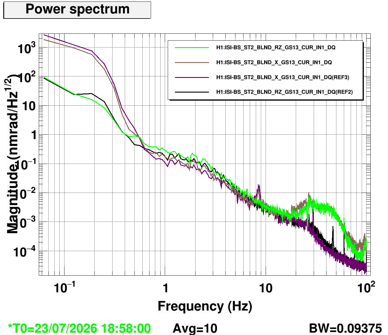
I used the earthquake down time from the weekend to look at the health of the BSC2-ISI sensors.
Sensors look OK (including the newly replaced H1 L4C - see alog 90840) except for CPS ST2 H1 (see red curve on the last plot) with large noise below 1Hz. This will need an investigation (I would start by swapping cables at the field box to see if it's an in-chamber issue).
Dtt Template lives under /ligo/svncommon/SeiSVN/seismic/BSC-ISI/H1/BS/Data/Spectra/Undamped/bs_all_sensors.xml

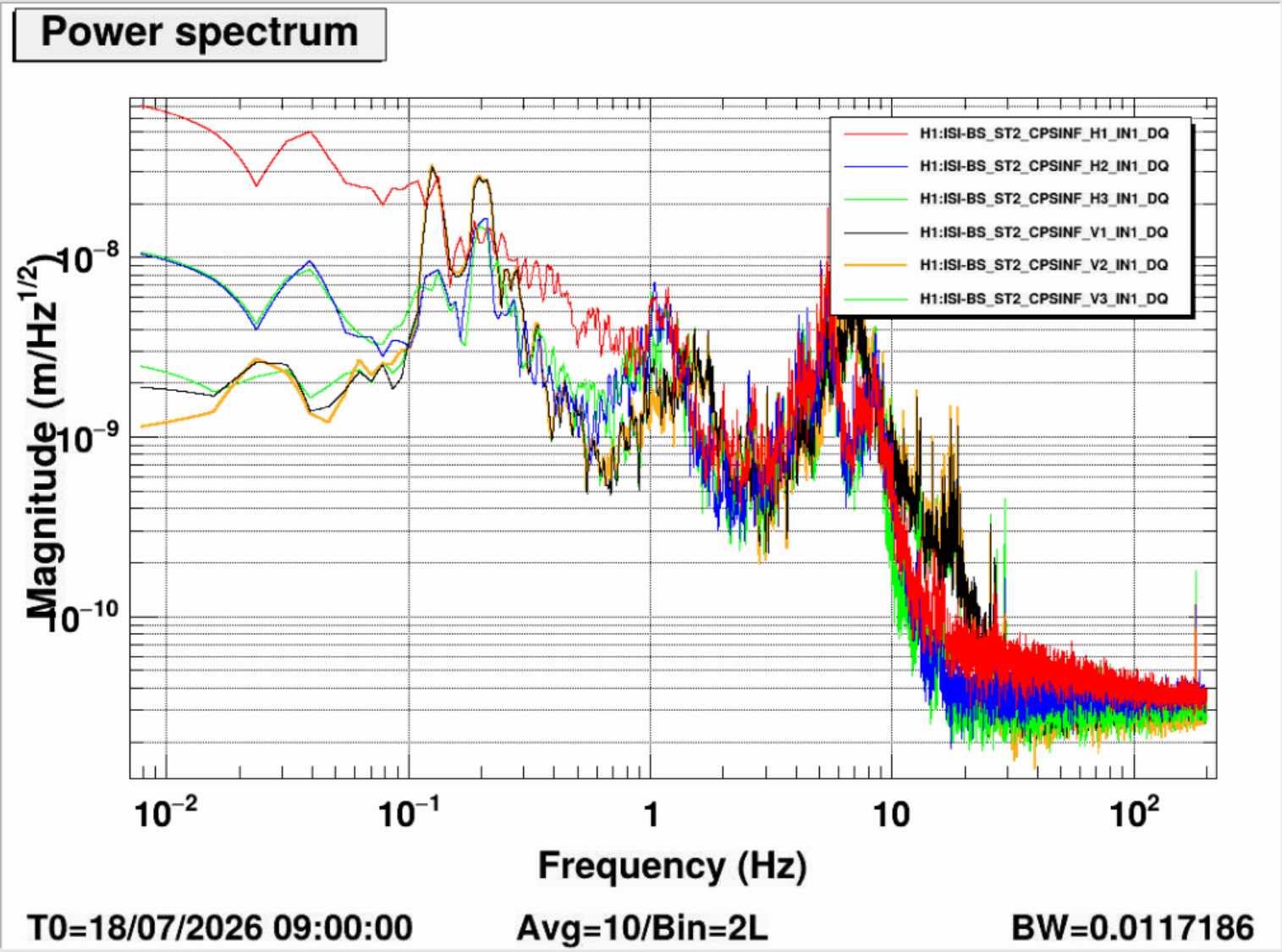
I had already done this test several years ago trying to diagnose the issue with BSC2, which, contrary to my comment in the alog Arnaud linked to, still has alot of flat looking excess noise in the 1-10hz. Arnaud's spectra here doesn't make me think this noise is due to a broken cps, the high frequency noise floor is unchanged, there's no evidence of glitching, unless it is some new failure mode.
Knowing that I would have few chances to try swapping in the near future, I did this over lunch when I went out to also unlock HAM1&2 hepi. I put BSC2 in damped, collected St2 CPS spectra, swapped the St2 H1 cps with a spare sensor, and got a comparison spectra. No change, see first attached spectra, refs are with the old H1 cps, live spectra are with the new sensor. I have left the spare sensor in for now, I will try to swap it back to the old sensor so we can preserve our ISI alignment (the new sensor reads a slightly different location that the old), but physically there should be no difference, the BSCs just use the free hanging position for the cps reference, unlike the HAMs.
Performance is no better with the new cps, as well, see second plot, refs are with the new cps, live is before the swap.

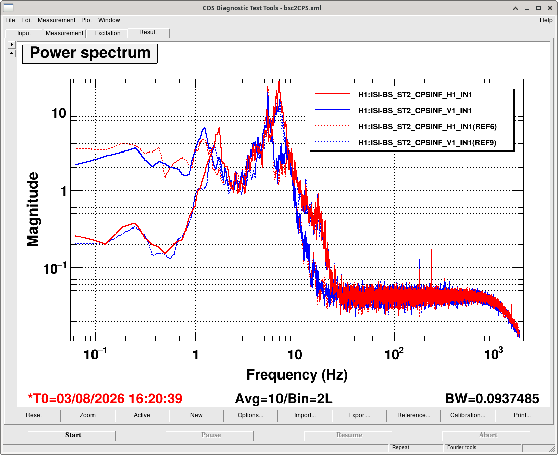
As dicussed with Jim on the phone it would be interesting to see the result of swapping H1 and V1 at the lemo input of the field cables - V1 noise is low enough between 10mHz-100mHz when the ISI is damped that the H1 noise would be obvious if it followed the cable.
Finally had a chance to repeat the test swapping st2 h1 v1 cps. Still no change, as I have seen when I did this test before. The excess low freq noise follows the in-air to feedthru and in-vac cables, so the problem is not from the satellite chassis or the CER rack. I can try to swap the cable from the feedthru to the satellite rack, but the work platform, crossbeam and feedthru protection make access to that difficult from pretty much any direction.
Attached spectra compare the nominal H1 V1 asds and the asds with the white in-air cables at satellite rack for st2 H1&V1 swapped. Dashed is nominal, solid is the swapped configuration. Red is the H1 channel, blue is the V1 channel.
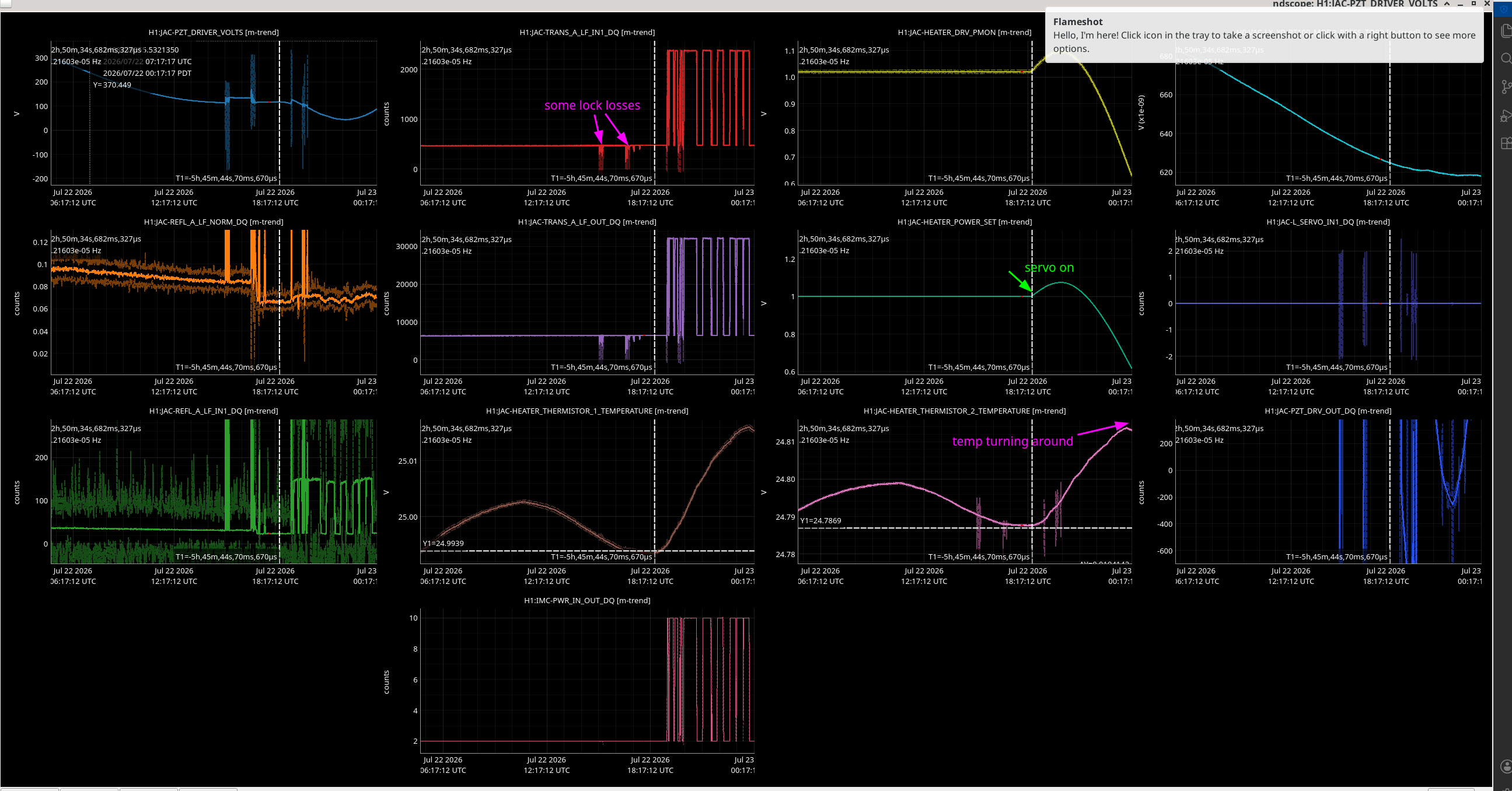
I tried the heater guardian today with a gain of 0.003 and a set point of 25 degrees seeing as it seems to have reached equilibrium around this value with no loop running and 1W input overnight. It looks like it overshot initially and is turning around and coming back to the set point of 25 degrees C now. Thermistor 1 is the loop sensor but I have marked the turning point on thermistor 2 in the attached picture. We still have some range on the PZT actuator (JAC-PZT_DRIVER_VOLTS is low rate channel from Beckhoff voltage driver and JAC-PZT_DRV_OUT_DQ is front-end PZT feedback channel for fast feedback) and the temperature actuator (JAC-HEATER_POWER_SET). I will get the operator to switch it off when they leave so we don't cause any pressure spikes overnight.
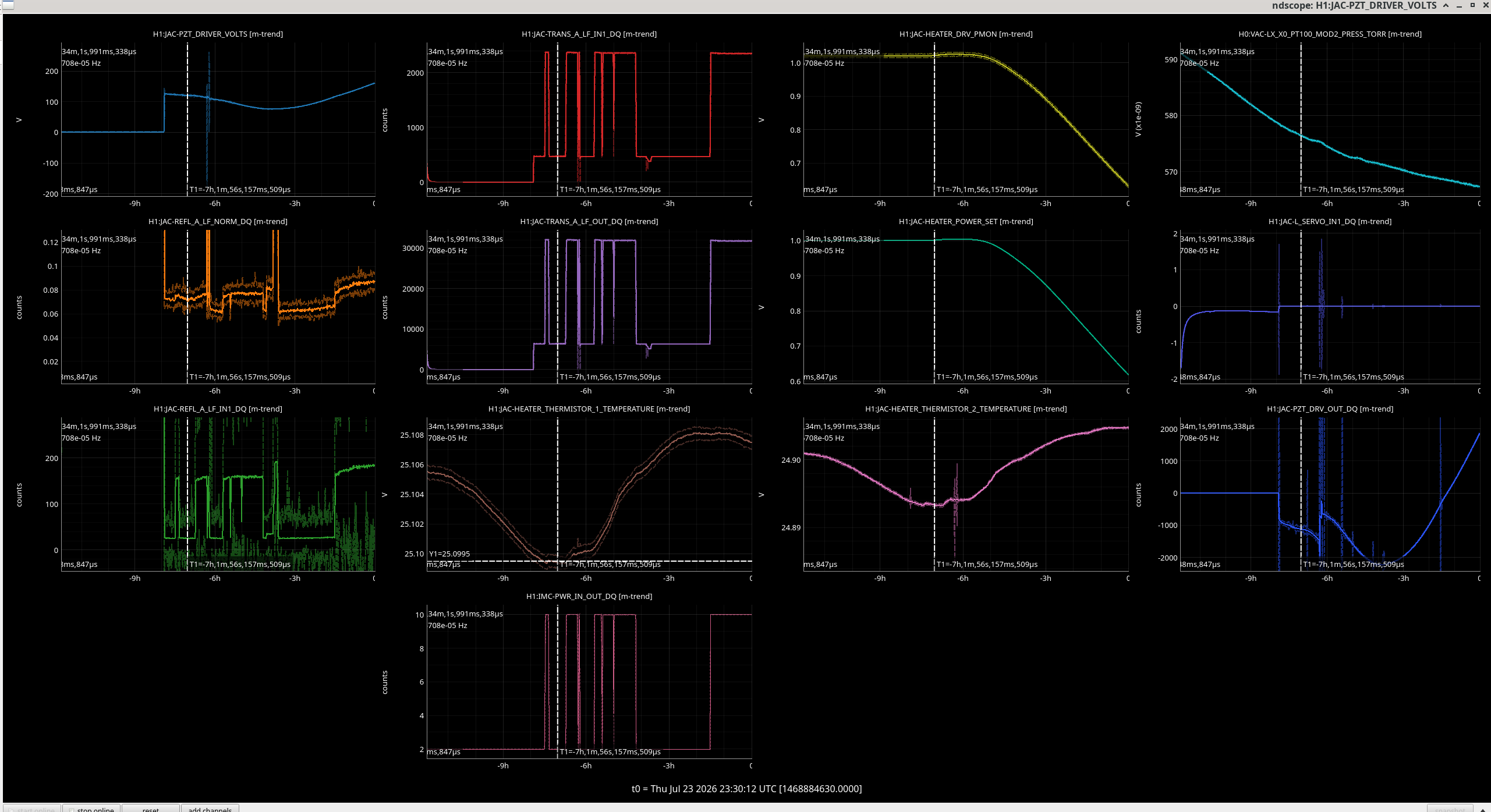
I did another test today with the same gain but the set point at 25.1 degrees C (the temperature of the thermistor 1 when I switched it on). It still overshot so we might want to test with a lower gain but it stopped the JAC from unlocking due to the PZT running out of range.
Attached is the trends from today (vertical cursor when i switched on the controller, horizontal showing the setpoint on the thermistor).
Summary: let's test tomorrow with a smaller gain.
Shoshana, Jim, Arnaud
The x6 HAM3 new CPS boards have been set to the following configuration (as per E2200455):
| board SN | probe SN | Location | |
| H1 | 29536 | 22777 | Slot 1 in crate +Y side |
| V1 | 38690 | 22781 | Slot 2 in crate +Y side |
| H3 | 12563 | 22779 | Slot 3 in crate +Y side |
| V3 | 38494 | 22775 | Slot 4 in crate +Y side |
| H2 | 23370 | 22778 | Slot 1 in crate -Y side |
| V2 | 11950 | 22780 | Slot 2 in crate -Y side |
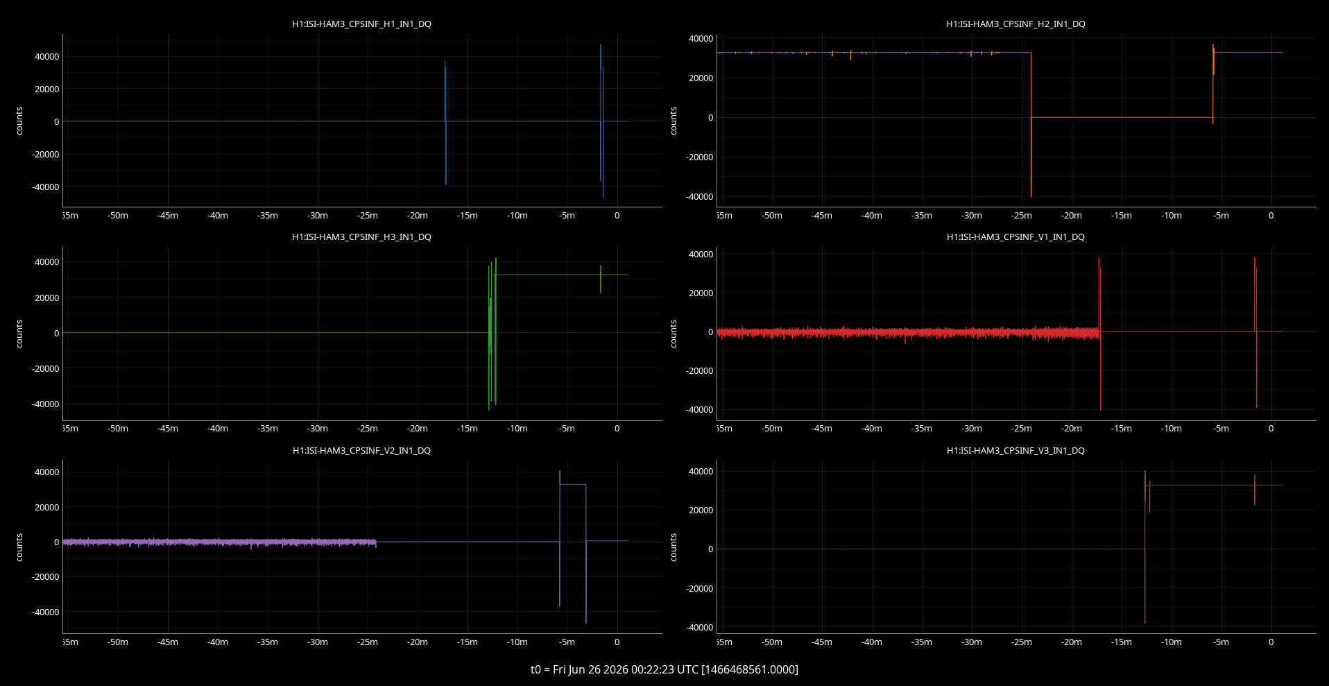
There was some glitching noticed on the channels that were in range prior to this work, which was fixed after this setting change (see attached). Two of the cards were set to Master before and Jim is confident this would have created problems.
Left to do :
1- Label the cards at the front of the boards with module SN and corner #
2- Disconnect the grounding to the chamber of the crate on the +Y side
3- Label the in-air lemo cables with H1, V1, H2 ...
4- Update ICS with the new boards SN
5- Gather the cards that were removed from WHAM3 to send back to microsense for recalibration with a new set of sensors (RMA)
The tracking spreadsheet for this ECR was updated here: E2500184
Cross referencing all logs related to this upgrade here :
Some install notes:
https://alog.ligo-wa.caltech.edu/aLOG/index.php?callRep=90791
CPS health check after install:
https://alog.ligo-wa.caltech.edu/aLOG/index.php?callRep=90911
https://alog.ligo-wa.caltech.edu/aLOG/index.php?callRep=90950
SUSPoint improvement from this upgrade:
https://alog.ligo-wa.caltech.edu/aLOG/index.php?callRep=91113