When I hammered the below table "beard" baffle on May 26 (alog90335), something wasn't correct with the way I saved the data or my configuration or something else. Either way, Jeff and went in today and hit that as well as the SPI ISIJ assembly with and without the cylindrical shroud (D2500030). Preliminary results are looking much better, so I'll clean those up and post them soon with a whole writeup.
In 89751 we found we could not trust the FC1 top mass osems for an accurate FC1 alignment, we then set an FC REFL iris on SQZT7 to help us capture correct FC1 alignment 89771, as we thought we couldn't trust any stage of the FC1 suspension. But this iris also depends on ZM1,2,3 which is confusing.
Since the FC1 issues this week, we checked that the sliders are working as expected 90466.
We have decided to not use the FC REFL iris to set FC1 as it puts FC1 in a very different position to O4. We will align FC1 using the slider positions from O4. This is as in the December vent, between the O4 under-vacuum and the vents, doors off time, the FC1 WIT channels were within ~10-20urad, see top two rows of table below. Additionally in February when we had our FC1 trouble, we though that we would have been fine if we had never touched the FC1 sliders.
From August to November, the FC1 M3 Pitch WIT drifted between 175 and 195urad so where we are currently at 170urad is not far outside of this range.
| FC1 | Temp (Zone 4 G) |
Pitch | Yaw | ||
| Slider | M3 WIT | Slider | M3 WIT | ||
| Under-VAC, O4, Nov 8th 2025 | 67.6degF | 225 | 195 | -153 | -202 |
| Vented, Dec 9th 08:30 UTC | 71.2degF | 231 | 181* | -153 | -201 |
| Vented, 04 June 2026 16:45UTC When tring to use 89694 (good FC flashes alignment) for ZMs and FC REFL iris for FC1 |
71.1degF | 217 | 169 | 52 | 38 |
| Vented, 04 June 2026 20:41UTC Back to O4 sliders. |
71.3degF | 225 | 170 | -153 | -202 |
* drifted down to 162 over next week
We have put ZM1,2 3 back to their O4 sliders as a starting place, you can see below that the top mass osems say this is not the same location as when under vacuum but we don't think this is trustworthy. We will change these alignments as needed to get the FC beam to retroreflect off FC1.
| To match 89694 (good FC flashes alignment). 04 June 2026, 16:45UTC |
O4 time. Nov 8th 2025, 20:30UTC |
Sliders back to O4 values 04 June 2026, 21:15UTC, plot |
||||
| Sliders | WIT* | Sliders | WIT* | Sliders | WIT* | |
| FC1 P | 217 | 169 | 225 | 195 | 225 | 171 |
| FC1 Y | 52 | 38 | -153 | -202 | -153 | -202 |
| ZM1 P | 530 | 420 | 0 | -390 | 0 | -253 |
| ZM1 Y | 0 | 417 | 0 | 432 | 0 | 429 |
| ZM2 P | -429 | -399 | -196 | -273 | -196 | -183 |
| ZM2 Y | -132 | 184 | -235 | -43 | -235 | 101 |
| ZM3 P | -474 | -422 | -190 | -68 | -190 | -57 |
| ZM3 Y | -367 | -282 | -300 | -463 | -300 | -261 |
*WIT is M3 WIT for FC1 but for ZMs there is no bottom mas WIT so we're using M1_DAMP_{P,Y}_INMON
R. Short, J. Oberling, J. Kissel
This afternoon we installed the shutter in the SPI pickoff path on the PSL table. We installed it in between the 2 SPI lenses. The cable was tied down with some dog clamps and cable ties, and we checked to make sure it was well clear of all known beams (it doesn't really look like it in the picture, but the shutter cable is ~3 inches away from the ALS beam and cannot drift into its path). Once we ran the cable outside the enclosure, Jeff plugged it into the driver and we ran several on/off tests, with the shutter successfully actuating as expected, every time. I'll update the as-built PSL table layout to include the shutter.
[Tom, Oli]
Summary: There is a polarity flip between the BOSEM and QOSEM coils due to the wiring of the QOSEM flexi-circuit. To maintain consistency with existing BOSEM controls a sign flip should be implemented in CDS coil drives.
When commissioning the damping loops for the BBSS on the teststand, we noticed that there was a sign flip required in the QOSEM coil drive for the loops to be stable, when copying over the existing BOSEM damping. See LHO alog 90441. After some investigation, this sign flip is due to a polarity flip in the wiring from the coil drivers to the QOSEM coils. The QOSEM coils are wound in the same direction as the BOSEM coils, however on the QOSEM flexi-circuit I accidentally flip the coil connections with respect to that of the BOSEM. All QOSEM version to do date suffer from the coil sign flip.
In the attached screenshot, we see the BOSEM flexi-circuit has this weird flip between the coil pads (on the very left) and the uDB9 connection. I did not copy this flip over to the QOSEM flexi, which has caused this coil polarity flip.
J. Oberling, P. Thomas, R. Short
TLDR - Following the power outage(s) over the weekend, we've successfully restored the PSL.
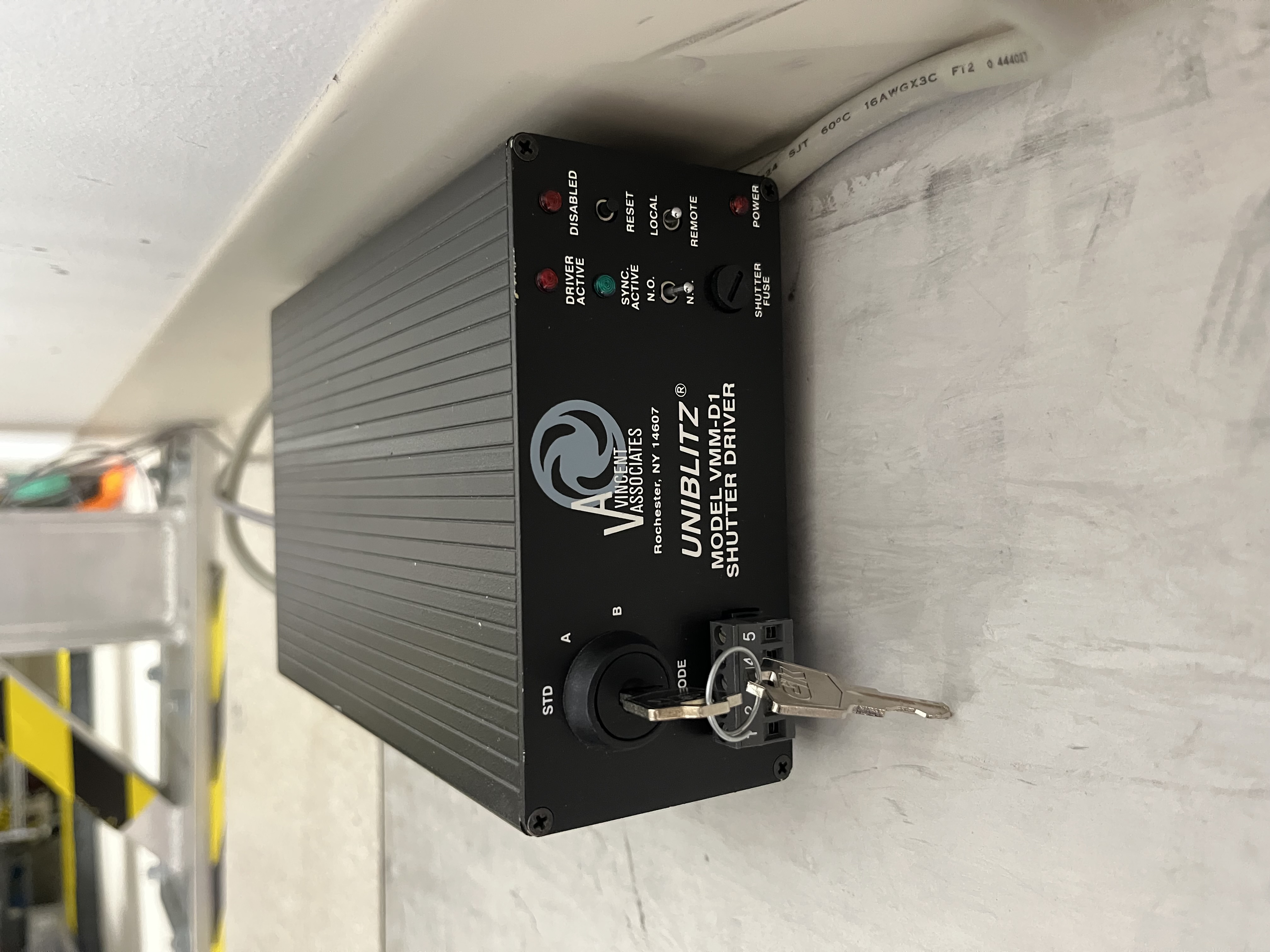
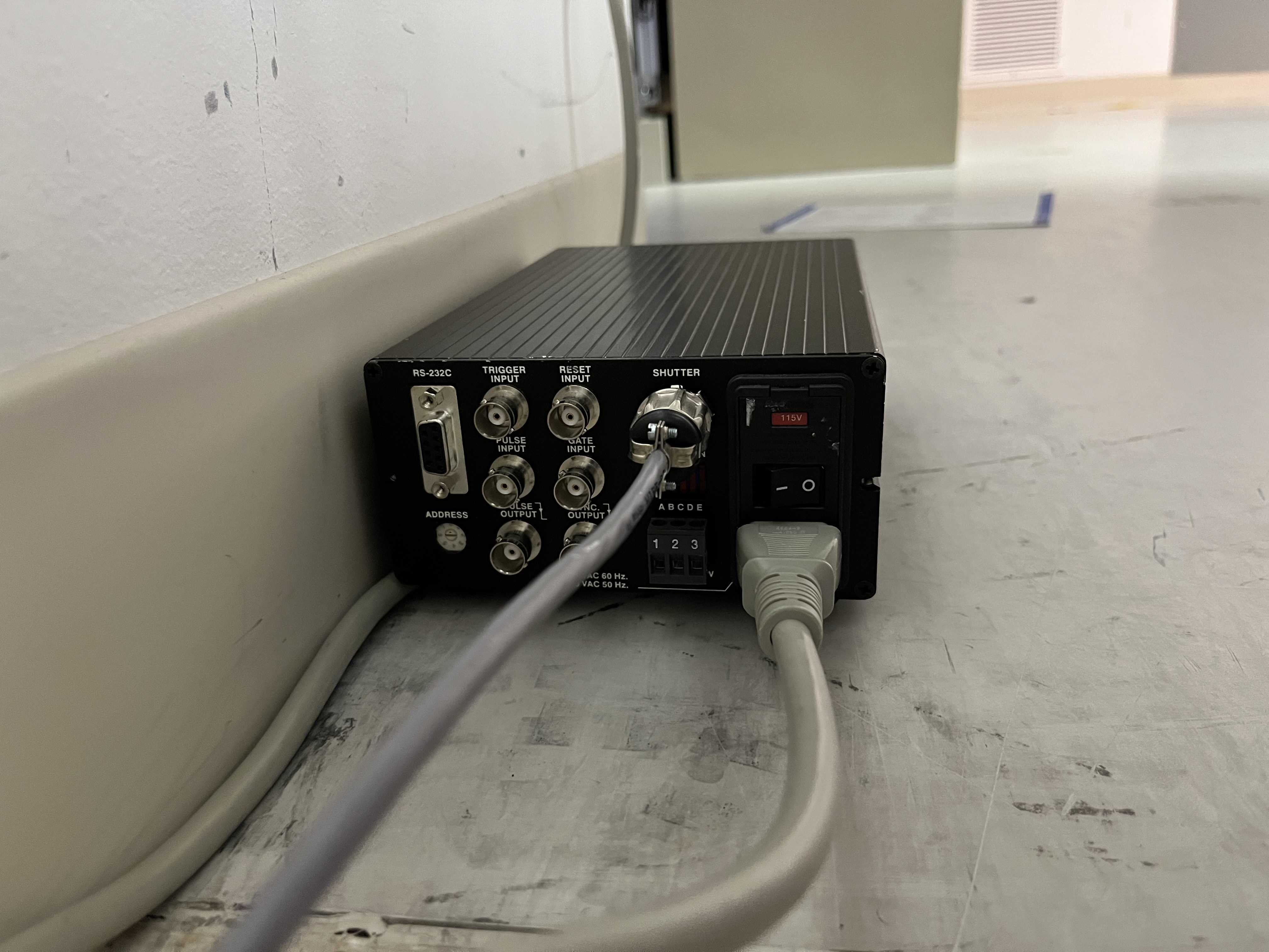
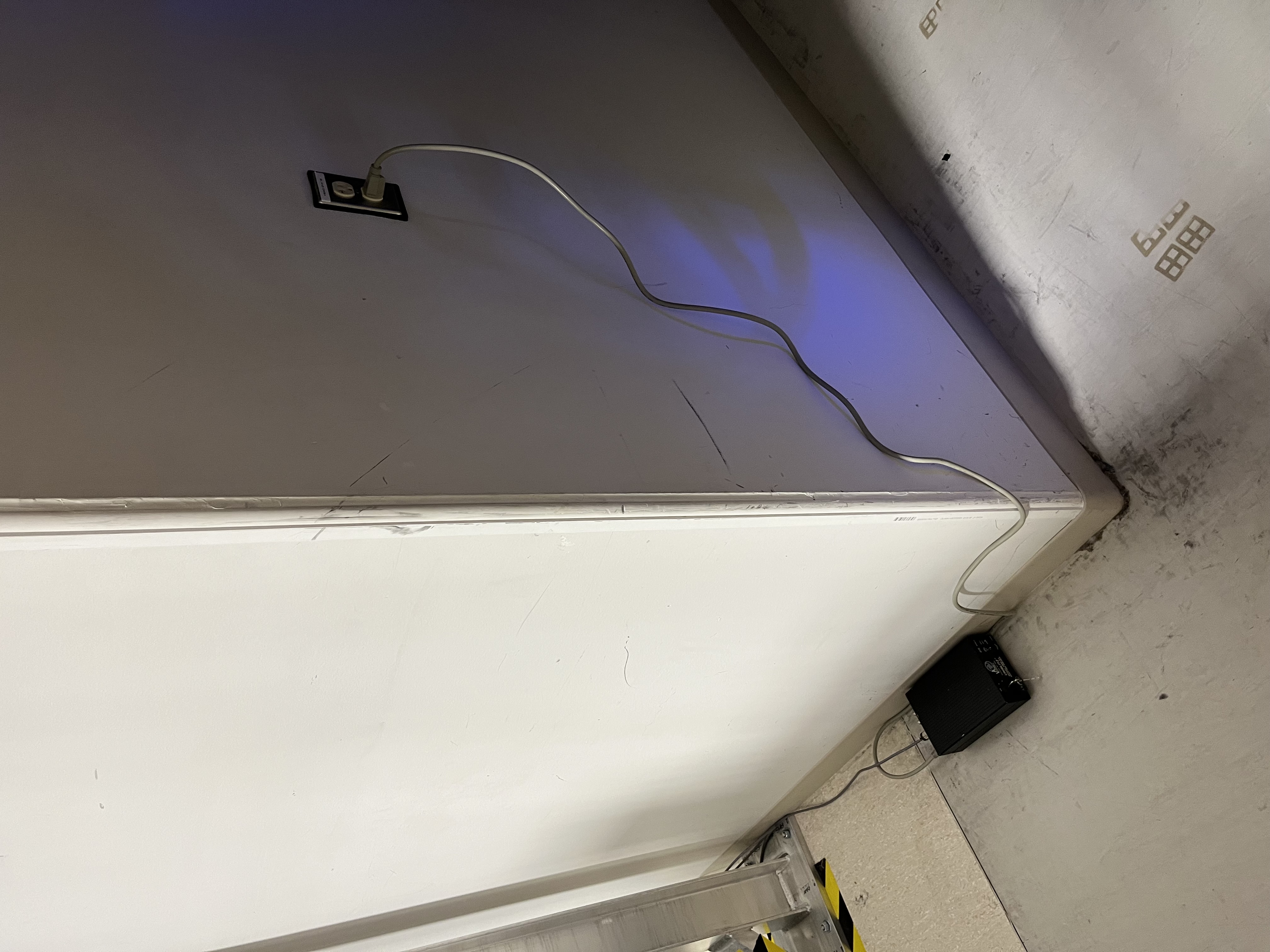
Monday morning, Jason started by turning back on the benchtop power supply behind the PSL racks in the LVEA which powers CB2 and then restarted the Beckhoff computer in the diode room (we've seen in the past that the Beckhoff computer needs everything to be powered on before it boots so that it can "see" everything). However, even though the EPICS IOC auto-started when the computer came up, the PLC did not, so we were unable to bring the system up at first. I was able to find and launch the correct PLC (which, for our future reference is in the "Projekt_LIGO_240124" folder), but we noticed after the GUI came up that we were missing the amplifier PD WD, one of the newest additions to the software. Thinking we had an old version of the software somehow, we called in Patrick, who reminded me that instead of just starting TwinCAT in run mode, I should have also logged in and started the PLC to pull in all the updates to the code. This brought the Beckhoff computer back to full functionality, and we were able to bring the laser up without issue after clearing the site laser interlock (which wouldn't clear until the Beckhoff computer was functional). As usual, our calibration settings and operating hours for the NPRO, amps, and chiller were lost with the computer reboot, so we found the last saved screenshot of the settings table we took after the last outage (alog88368) and used it repopulate the table. The operating hours were all fixed also since we could trend back what they were before the outage. A new screenshot of the settings table is attached.
Relocking the PMC went without issue, and it's now been coming up to temperature since Monday with the transmitted and reflected powers slowly settling out. I can tell by the camera spots and the lower transmitted power that some alignment is needed into the PMC, which we can do eventually. The PMC relocked at a temperature a couple degrees cooler than before, which we've seen before, so this slightly different operating point isn't too surprising.
Trending the enclosure temperatures shows that the environmental controls seem to have come back no different than before the outage.
Before starting the cage baffle install we took a reference of the optical levers (with ISI locked) such that later when we unlock the quad we can tell if there was a significant shift. NB there were small shifts at LLO when we installed these baffles and we are still baffled as to why. Since they attach to the cage, which is connected to the ISI and the ISI gets rebalanced, it's unclear why they'd shift more than some 20-30 urad.
I took one reference pre-vent, circa Nov 28, when we were still locking full ifo. The second reference is recent, at air, with the ISI locked.
| ITMX | pre-vent | vent, pre-work |
| date | Nov 28 '25 | Jun 3 '26 |
| sliders P,Y | -113, 110 | -35, 94 |
| oplev P | 8 | 0 |
| oplev Y | 6 | 0 |
| oplev sum | 3400 | 3200 |
| ITMY | pre-vent | vent, pre-work |
| date | Nov 28 '25 | Jun 2 '26 |
| sliders P,Y | -14, -18 | -90, -16 |
| oplev P | -30 | 0 |
| oplev Y | -15 | 0 |
| oplev sum | 9000 | 9000 |
After the cage baffle installation we freed the two ITMs and recorded again the sliders that would be required to bring the oplev to 0,0. ISIs still locked.
ITMX: -35 P, 94 Y (same as before) data from Jun 9
ITMY: -240 P, -16 Y data from Jun 5
ITMY shifted some in pitch but it is still within range. Assuming that it will shift back going to vacuum as it did above, then we would end up with some -170 in pitch, which is less than half range and fine to work with.
Ibrahim, Oli, Thomas, Betsy, Jim, Mitchell
Here's the analyzed data for the QOSEM transfer functions, as well as a comparison of transfer functions between the BOSEMs and the QOSEMs for the BBSS on the test stand. They're pretty similar.
I didn't modify the analysis script yet since we are currently only using the X of the QOSEMs, so I just exported the M1_OSEMINF_{F1,F2,F3,LF,RT,SD}_X_OUT_DQ channels in theplace of the M1_OSEMINF_{F1,F2,F3,LF,RT,SD}_OUT_DQ channels.
Data
/ligo/svncommon/SusSVN/sus/trunk/BBSS/H1/BS/SAGM1/Data/2026-06-01_1700_tfs/2026-06-01_1700_H1SUSBS_M1_WhiteNoise_R_0p02to50Hz.xml
r13024
Results
/ligo/svncommon/SusSVN/sus/trunk/BBSS/H1/BS/SAGM1/Results/2026-06-01_1700_tfs/2026-06-01_1700_H1SUSBS_M1_ALL_TFs.pdf
r13024
/ligo/svncommon/SusSVN/sus/trunk/BBSS/Common/Results/allbbss_BBSS_teststand_BOSEMsvsQOSEMs/allbbsss_BBSS_teststand_BOSEMsvsQOSEMs_ALL_TFs.pdf
/ligo/svncommon/SusSVN/sus/trunk/BBSS/Common/Results/allbbss_BBSS_teststand_BOSEMsvsQOSEMs/allbbsss_BBSS_teststand_BOSEMsvsQOSEMs_ALL_ZOOMED_TFs.pdf
r13025
Patrick T., Filiberto C., Richard M., Dave B., Jonathan H., Jim W. WP 13262. The summary of the work is detailed in the permit. There were some additional code changes needed to fix a scaling issue and some others made to clean things up. The only thing that should be left is to restart the DAQ to remove three channels. IOC code: https://git.ligo.org/cds/software/ads/ads-utils 9b98c481d6f9ab129fa4bc54475e05383d304aa2 https://git.ligo.org/cds/software/ads/epics7-ads c72c97eb4d1558d9de5c03234e90c8c651aab99b (in container), 9e5a10a014beeb0cb7b021649c459a0fa0488be7 (used to generated EPICS db) PLC code: https://git.ligo.org/cds/ifo/beckhoff/io 65f59557c1fefc90f4befc9338bd29a1fb27d8e0 https://git.ligo.org/cds/ifo/beckhoff/lho-hepi 3fd31d58fafc08e4d5a84dce1d0d57dfd8b6b74e
Shoshana, Alexandra, Jim, Arnaud, Fil
Yesterday's activity log:
| Nominal | New Fork (D2300094-v4) | New Fork + D230099 type2 (4g vs 2g type 1) | |
| Z | +186um | +189.8um | +229.2um |
| X | -2.4um | -3.75um | -3.75um |
The monitor channels in the CRS pre-amp D2500390 are connected up incorrectly. The following table details the current connections: HoQI/TEST POINT CONNECTION - MON CHANNEL CONNECTION HA PDS - HD PDS HA PDC - HA PDC HA PDMC - HD PDMC HB PDS - HC PDS HB PDC - HB PDC HB PDMC - HC PDMC HC PDS - HB PDS HC PDC - HC PDC HC PDMC - HB PDMC HD PDS - HA PDS HD PDC - HD PDC HD PDMC - HA PDMC
TITLE: 06/04 Day Shift: 1430-2330 UTC (0730-1630 PST), all times posted in UTC
STATE of H1: Planned Engineering
OUTGOING OPERATOR: None
CURRENT ENVIRONMENT:
SEI_ENV state: MAINTENANCE
Wind: 8mph Gusts, 4mph 3min avg
Primary useism: 0.01 μm/s
Secondary useism: 0.13 μm/s
QUICK SUMMARY:
BSC2 cartridge will be flying back in after lunch today! The LVEA will be going to LASER SAFE soon but is currently still LASER HAZARD
(Jordan V., Gerardo M.)
We have noticed that the dew point at the dryer towers has been increasing since opening to HAM7 and or related to power glitch last Saturday, we are still looking into it.
We have had a constant dew point at the dryer towers of -72 oC, and now we are at -57 oC, because of those numbers we ran a short test, once work was finished for the day in-chamber, we stopped the purge air to the LVEA to see what the effect was on the drying tower's dew point, it changed but very slow, we started at -57 oC and after 20 minutes we ended up at -59 oC, and we noted that the right tower may be in trouble since the dew point did not improved while this tower "works", the dew point instead went up by the one degree, erasing the improvement of the left tower. We will look more into it.
To complete the test we took a dew point measurement at the point of use in the LVEA, and we got a -40.7oC, getting close to a bad dew point, and remember this is while no in-chamber work is going on, so please mind those C3 soft covers on chamber doors, thank you.
Today I power cycled the dryer towers for the purge air system, I did this to shut it off in a controlled manner instead of a power glitch/outage, like the ones from last Saturday, see entry here, and then restarted the unit back up, the dew point at the dryer towers improved by 4 degrees.
Also, I took a couple of dew point measurements at different places:
In conclusion, despite the great demand of purge air, the dew point still is good, but please don't waste it, if you can please keep those C3 door covers closed. Thank you!
A. Effler, R. Schofield, R. Short
All of the new SLiC baffles have been installed on both ITMX and ITMY (both the test mass and compensation plate sides), but the CP side of ITMX still will need some alignment positioning touched up. Earthquake stop brackets on the test mass faces for both quads were also swapped out to accommodate for the new baffles.
One person always remained near the open door in BSC1 while others were around the corner working in BSC3, and oxygen monitors were worn out of an abundance of caution.
Sheila, Begum, Ryosuke, Camilla
Sheila checked that FC1 is now working as expected but was not in May 90462.
Started the morning by setting FC1 to the FC REFL iris ZM1,2,3 sliders set to 90183 (when Sheila had the beam on SQZT7), we then set irises after ZM1 and ZM3. Doing this clipped the return beam on B:L1 aperture, this is expected as we could not get the return beam through the OPO when FC was aligned in Feb. Later we realized that this doesn't make scene, so set ZM1,2,3 sliders set to when we had good FC flashes in 89694 and then FC1 was moved to get the beam centered on the FC REFL iris, again this clipped the return beam on B:L1 aperture but the beam was considerably higher at the ZM3 iris than when we originally set it. Around or a little higher than 6.25". Tomorrow we will fully think this though and compare to O4 times.
We locked the OPO SUS iteratively looking at the beams off the OPO. It was finally lock with the FC REFL beam getting to the second iris but not centered and when we changed the alignment to the IR SQZT7 alignment, the beam made it through both irises when closed.
Sheila, Begum, Ryosuke then took beam profiles of the beam after ZM1 and ZM2 with the borrowed Phasics camera.
From 60068: If the beam coming out of VOPO is level with ISI surface, it's nominally 5.532" high, the beam travels up from ZM2 toward ZM3 to raise the beam height by 0.756".
So the beam would be 6.288" at ZM3 and FC1. This matches with our beam height measured yesterday at the ZM3 iris.
As the OPO has been locked in the same alignment is it's free hanging alignment, when the sliders are at ZM4 (P: -453.4, Y: -1275.0) and ZM5 (P: -258.0, Y: -761.0) as attached screenshot, when the beam is centered on the ZM4 iris the alignment can be recovered to the SQZT7 and the IR path irises.
Before locking down the ITM suspensions as part of the new baffle installations, we measured the positions of each test mass and compensation plate (CP) from the outer bevel to the inner cage:
EDIT: clarifying that "left" and "right" here refer to when looking at the face of either the test mass or CP, so left and right flip when going between TM and CP on the same suspension.
ITMY
Compensation Plate -
Test Mass -
ITMX
Compensation Plate -
Test Mass -
See attached photots for Anamaria's sketches of nominal positions and how they relate to the baffles.
For reference I got these numbers from the following e-drawing files:
HR cage baffles: DCC D2500081 FULL ASSEMBLY D2500081 A+, SLIC, QUAD SUS CAGE BAFFLE ASSY2.easm
CP cage baffles: DCC D2600035 D2600035 A+ SLIC CP SUS CAGE BAFFLE ASSY-15deg review2.EASM
For the keen eye you'll notice that the CP optic and the tests mass are not at the same height when in reality they should be. Because the CP optic isn't quite well aligned to the cage in this drawing in an IAS sense, it's ok because the baffle IS well aligned to the optic so the relative numbers we would use to align are, well, relative and hold true.
J Kissel, T Shaffer
All plots are in the accelerometer axis as defined below for each test. The measurement numbers were just for my own organization within the B&K software.
ISIJ
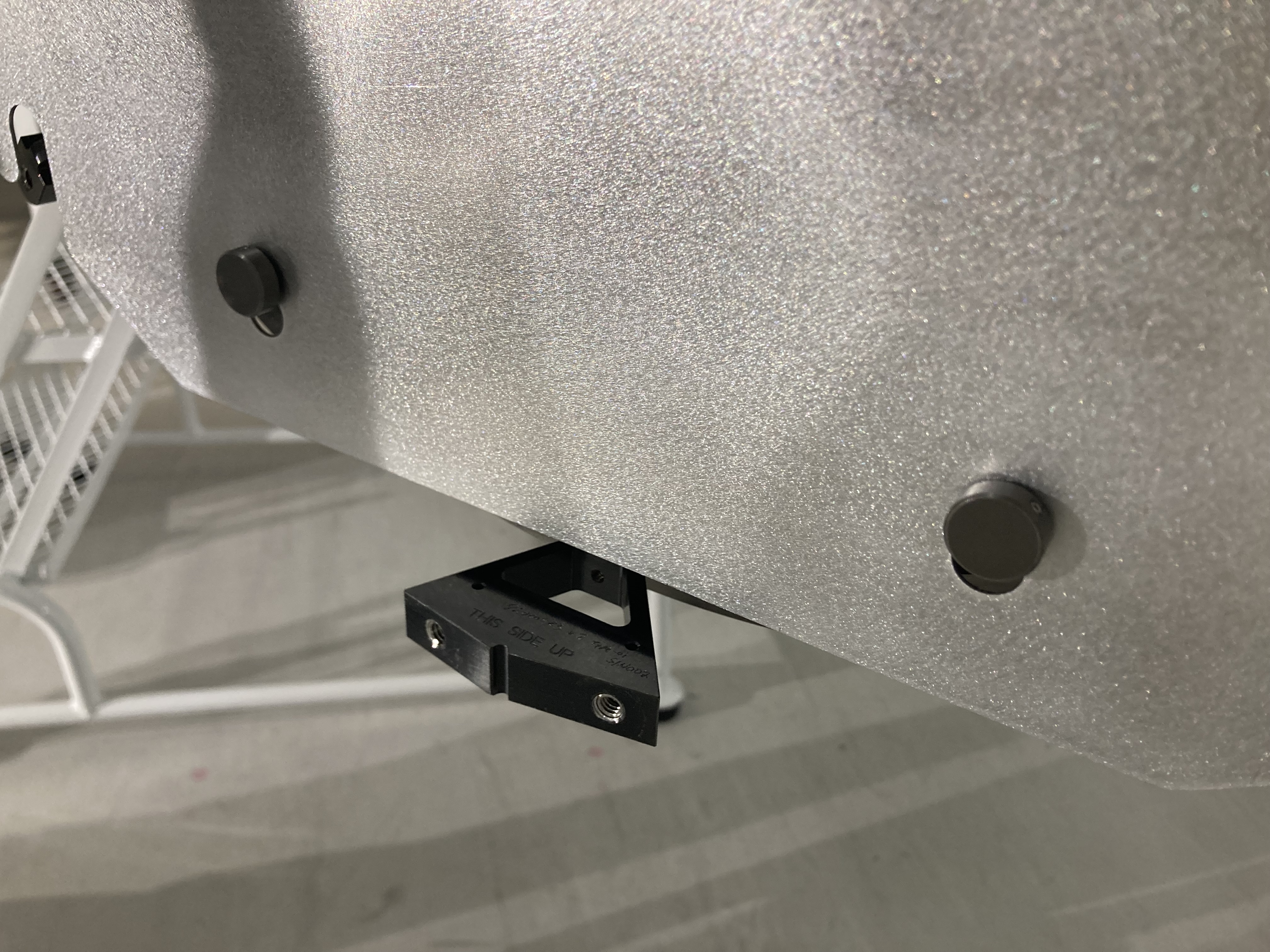
We did this in two stages, one set with the D2500030 cylindrical shroud and one set without. The accelerometer was mounted on a bolt hole below the ISIJ on the HAM face (photo).
The shroud has clear resonant peaks at 137, 196, 314Hz. It was ultimately decided to leave this piece off for now.
Below Table Baffle
Measuring the central below table baffle (D2600042) with the accelerometer mounted on the L bracket (D1700264) on the outermost bolt hole (photo). The accelerometer axis X,Y,Z = IFO -Z,Y,X.
Meas 1 - First hit IFO +X (+Z acc) bottom of L bracket - attachment 4
Meas 2 - hit in -Y IFO (-Y acc) on L bracket - attachment 5
Meas 3 - hit in +Z IFO (-X acc) L bracket bottom. Note that the bracket is tilted in the IFO -X direction. - attachment 6
There is a small peak at 87Hz.