Displaying reports 561-580 of 88336.Go to page Start 25 26 27 28 29 30 31 32 33 End
Reports until 15:29, Thursday 28 May 2026
LHO VE
jordan.vanosky@LIGO.ORG - posted 15:29, Thursday 28 May 2026 - last comment - 15:33, Thursday 28 May 2026(90371)
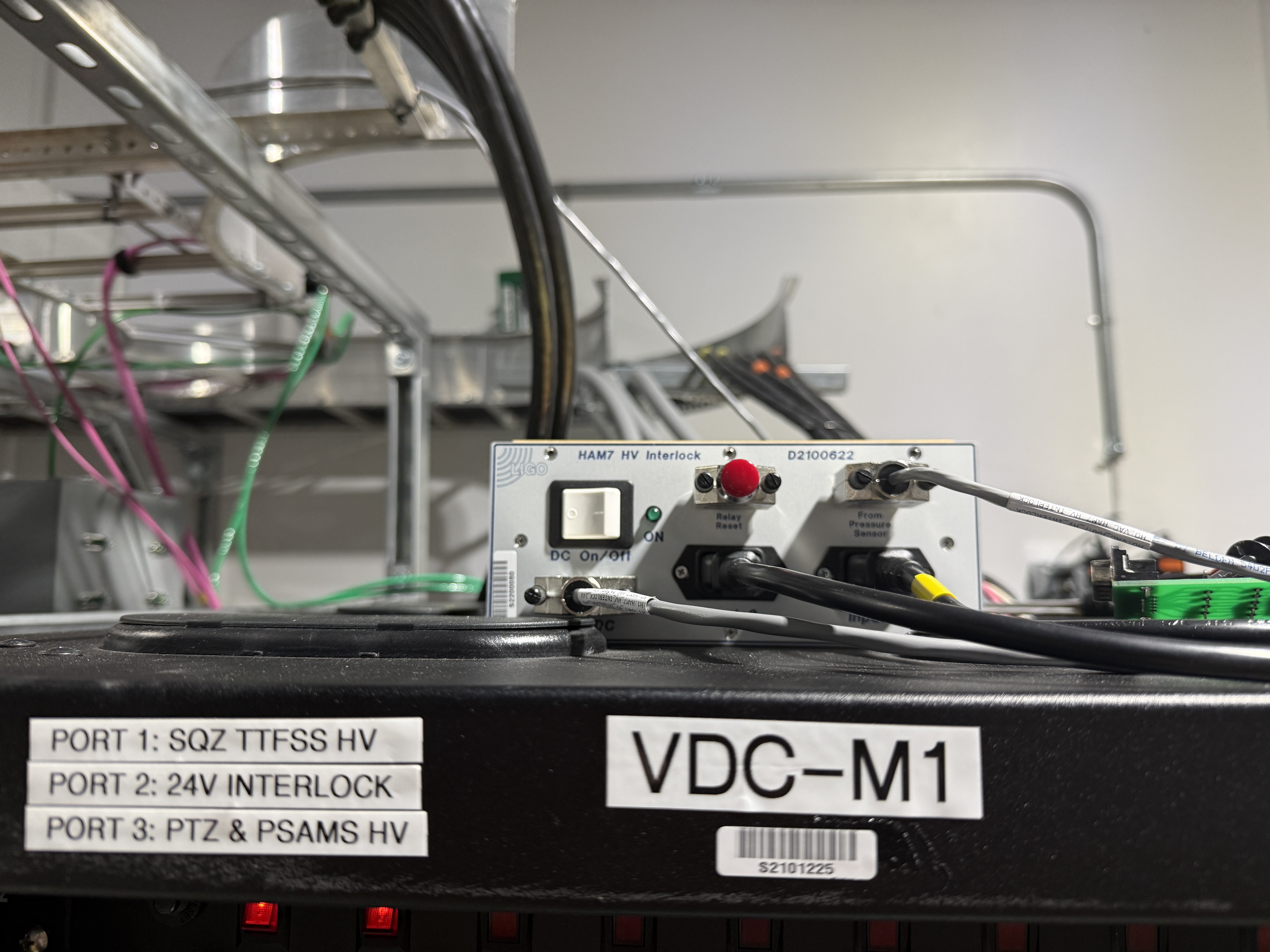
Prep for HAM7 Vent, High Voltage Disabled

Jordan, Travis

To prep for the HAM7 vent we followed the procedure M1300464 to disable the in vacuum high voltage sources and heating elements.


Comments related to this report
travis.sadecki@LIGO.ORG - 15:33, Thursday 28 May 2026 (90372)
Images attached to this comment
H1 General
mitchell.robinson@LIGO.ORG - posted 09:52, Thursday 28 May 2026 (90368)
Elliptical Baffle Assemblies Removed from Chamber

Corey, Randy, Mitchell

The two Elliptical Baffle assemblies that were taken down for the cartridge de-install have been removed from chamber. These two baffle assemblies will likely not be used again because of the new Cage baffle assemblies.

LHO VE (VE)
travis.sadecki@LIGO.ORG - posted 09:45, Thursday 28 May 2026 (90367)
Quarterly Functionality Test Performed on EX/MX Turbo Pumps

FAMIS tasks 31323 and 31308, WP 13258

Procedure checklist for both stations completed.  No issues were identified at this time.

MX: Scroll pump hours: 241.1
       Turbo pump hours: 153
       Crash bearings: 100%

EX: Scroll pump hours: 7161.4
       Turbo pump hours: 1113
       Crash bearings: 100%

H1 CDS
david.barker@LIGO.ORG - posted 09:41, Thursday 28 May 2026 (90366)
IOC container work

pt100a:

I cleaned up and standardized its container build area. Required a few restarts of the IOC.

kobe_oiltp:

This had been running on opslogin0 in a tmux session. Today I created a container for this IOC, added it to the cluster and retired the tmux.

Images attached to this report
LHO General
ryan.short@LIGO.ORG - posted 07:38, Thursday 28 May 2026 (90365)
Ops Day Shift Start

TITLE: 05/28 Day Shift: 1430-2330 UTC (0730-1630 PST), all times posted in UTC
STATE of H1: Planned Engineering
OUTGOING OPERATOR: None
CURRENT ENVIRONMENT:
    SEI_ENV state: MAINTENANCE
    Wind: 2mph Gusts, 0mph 3min avg
    Primary useism: 0.03 μm/s
    Secondary useism: 0.29 μm/s 
QUICK SUMMARY: Work continues today on the BBSS on the test stand and prep begins at HAM7 for doors to be removed next week. No alarms overnight, temperatures and dust counts looks good.

H1 SUS
ibrahim.abouelfettouh@LIGO.ORG - posted 17:35, Wednesday 27 May 2026 (90364)
BBSS Alignment Work - Done

Ibrahim, Betsy, Oli, Jason, Ryan C

Today, we finished with the FARO team (Ryan C and Jason) and confirmed that Pitch, Yaw, Vertical, Length (in-out) and Transverse (side-side) are all aligned within spec, which concludes the alignment of the BBS01 optic about the BBSS suspension - specific numbers in alog 90363

Transfer functions were taken throughout and can be found in alogs: 90356 , 90362.

Overall, the suspension dynamics with BOSEMs look good and now we're preparing for QOSEM install.


H1 AOS (SUS, SYS)
jason.oberling@LIGO.ORG - posted 17:34, Wednesday 27 May 2026 (90363)
BBSS Test Stand Alignment Complete (WP 13255)

R. Crouch, J. Oberling, B. Weaver, I. Abouelfettouh

We have completed the BBS test stand alignment.  After several rounds of yaw adjustment and figuring out the mechanics and what was rubbing where, we finally arrived at a yaw alignment within tolerance with everything torqued down and no rubbing in the SUS chain.  In comparison, pitch alignment was a few twists on the adjustable mass in the PUM, maybe 20 minutes in total.  The final pointing alignment deviations (yaw direction assuming a top-down view):

After the pointing alignment was complete we then moved back to the AR side to check that the position had not changed.  The BBS cage has not been moved on the ISI, so our alignment of the cage reported here is still valid.  The results (tolerance for all is +/- 1.0 mm):

Rotating from our IAS equipment basis to the IFO axes, shifting the deviations from the AR to the HR surface, and adding the pointing alignment, the final test stand position of the BBS HR surface is shown in the below table (CW = clockwise; CCW = counterclockwise; reported assuming a top-down view):

  Target Actual Deviation Tolerance
X -202.6 mm -202.3 mm +0.3 mm +/-1.4 mm
Y -184.1 mm -183.8 mm +0.3 mm +/-1.4 mm
Z -83.1 mm -83.2 mm -0.1 mm +/-1.0 mm
Pitch -446 µrad (up) -431 µrad (up) +15 µrad (down) +/-55 µrad
Yaw (from -X axis) -785.918 mrad (CW) -785.758 mrad (CW) +160 µrad (CCW) +/-190 µrad

I've kept the yaw angles in radians for consistency, but converting them to degrees gives a target yaw from the -X axis of 45.0298° CW and an actual yaw of 45.0206° CW, with a deviation of 0.0092° CCW.

We've left the IAS equipment in the West Bay near the test stand in case we need to take a look at alignment again, but as of now the test stand alignment is complete.

H1 SUS
oli.patane@LIGO.ORG - posted 17:11, Wednesday 27 May 2026 (90362)
BBSS test stand TF quick looks after more FAROing

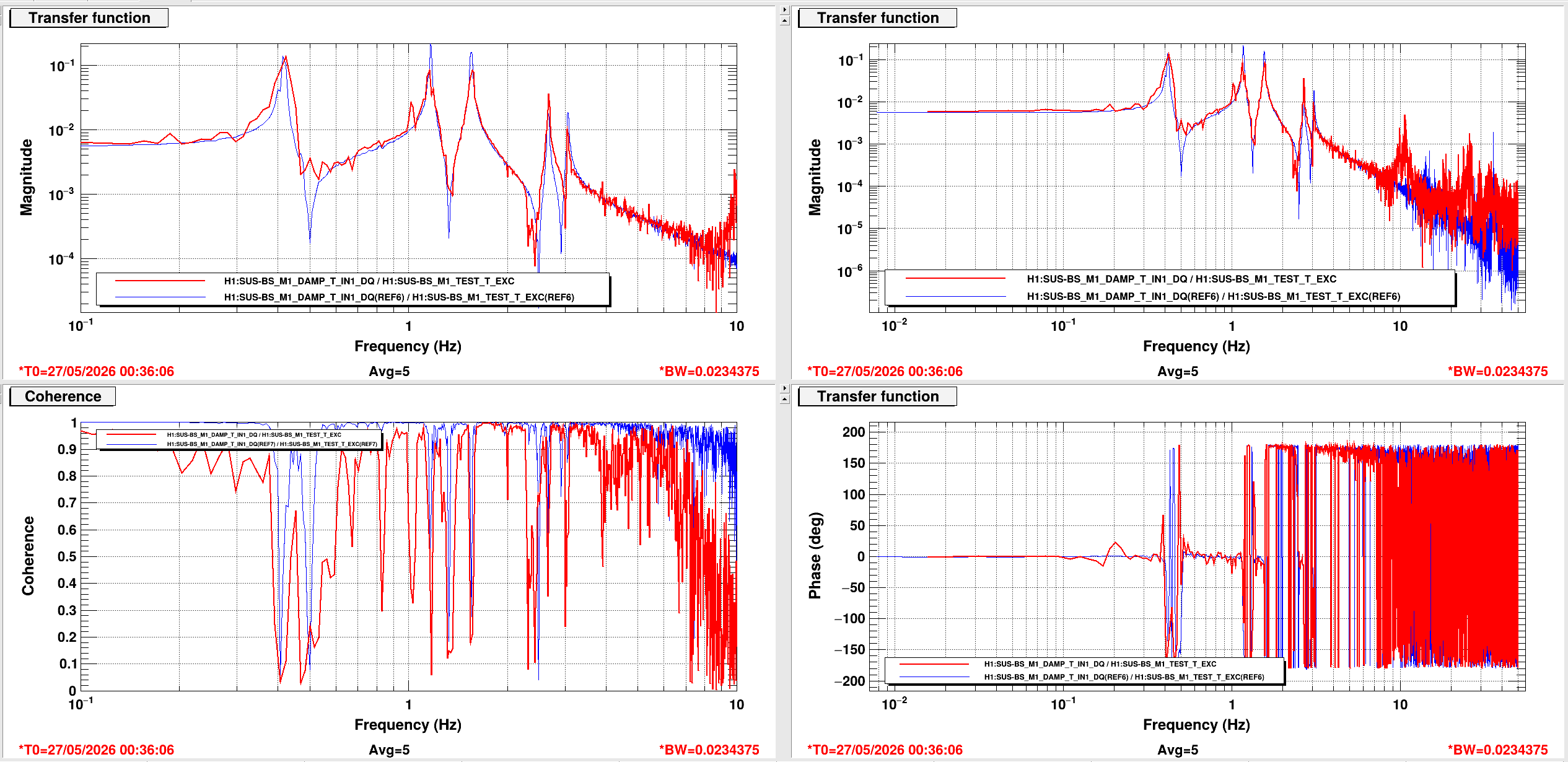
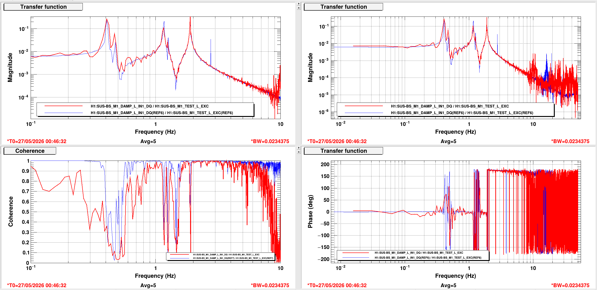
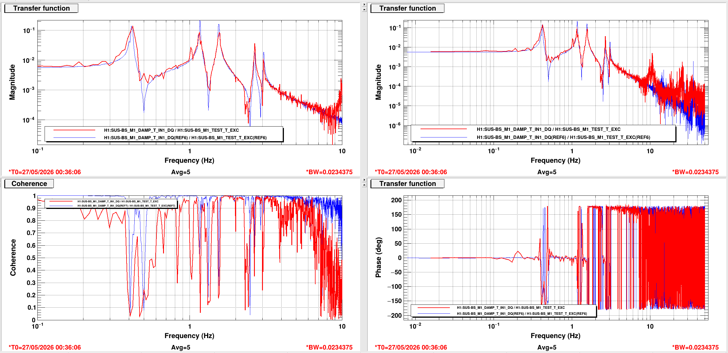
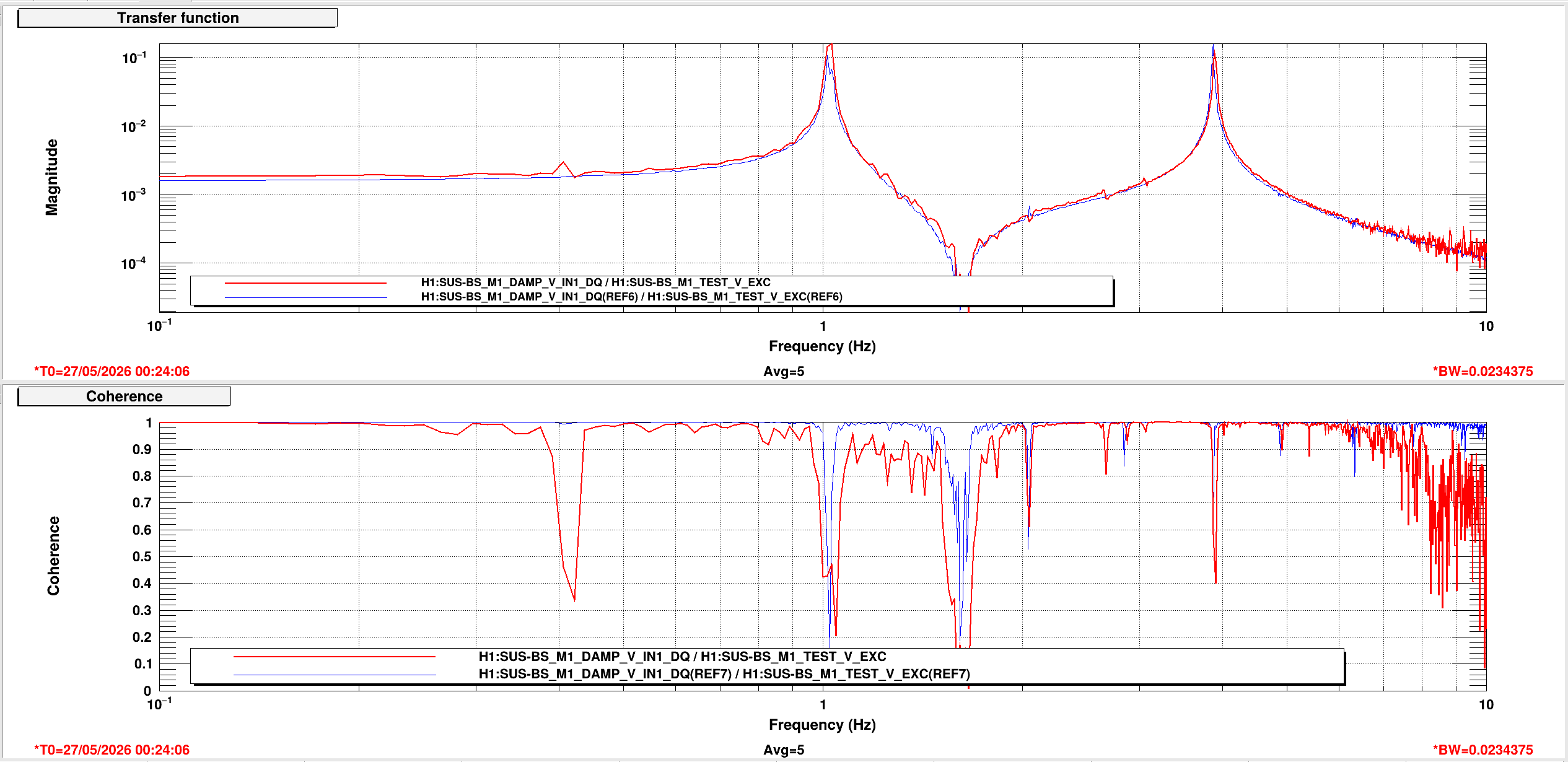
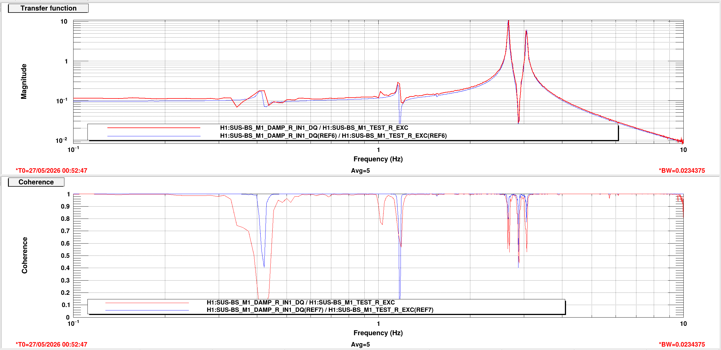
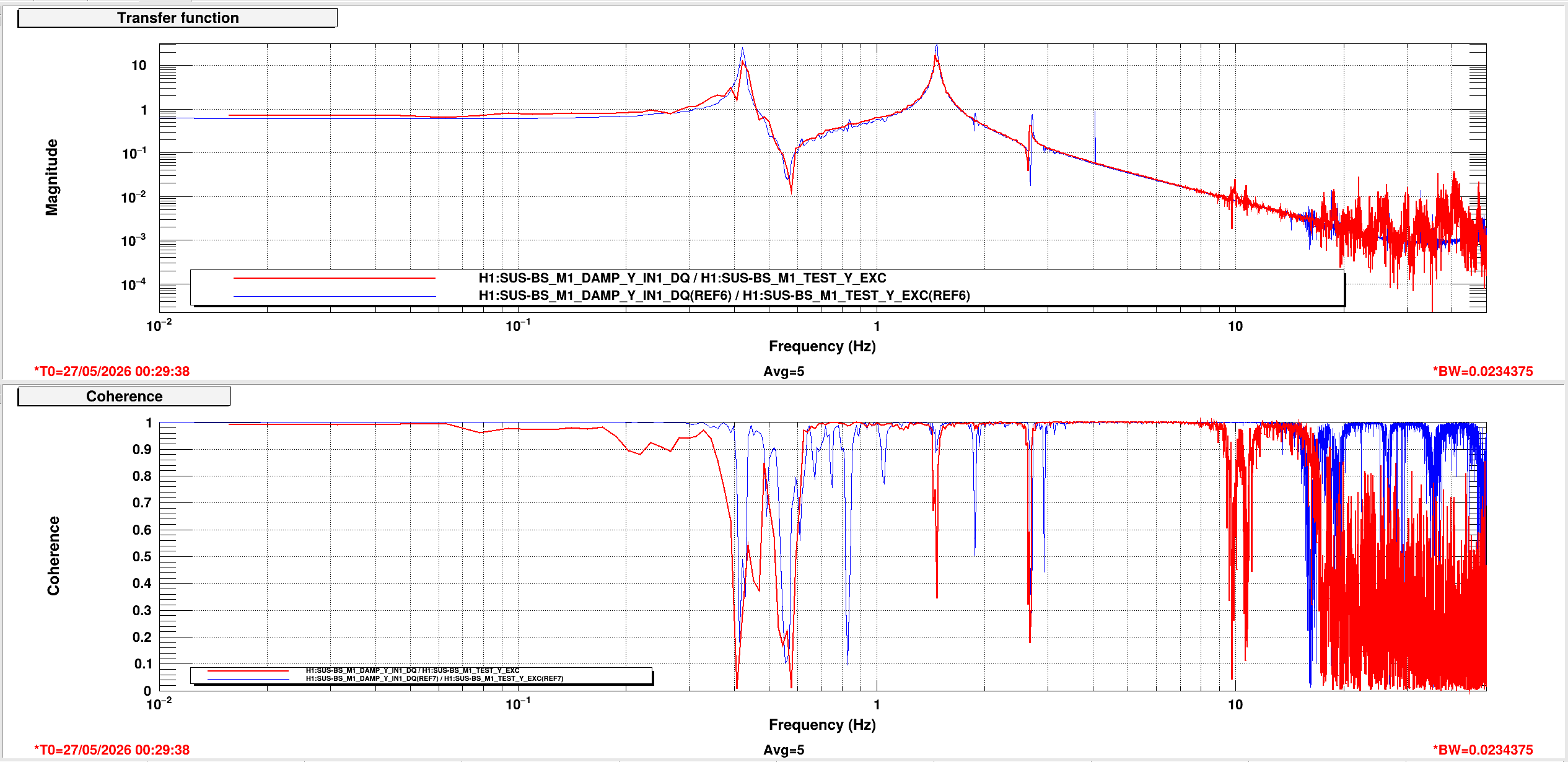
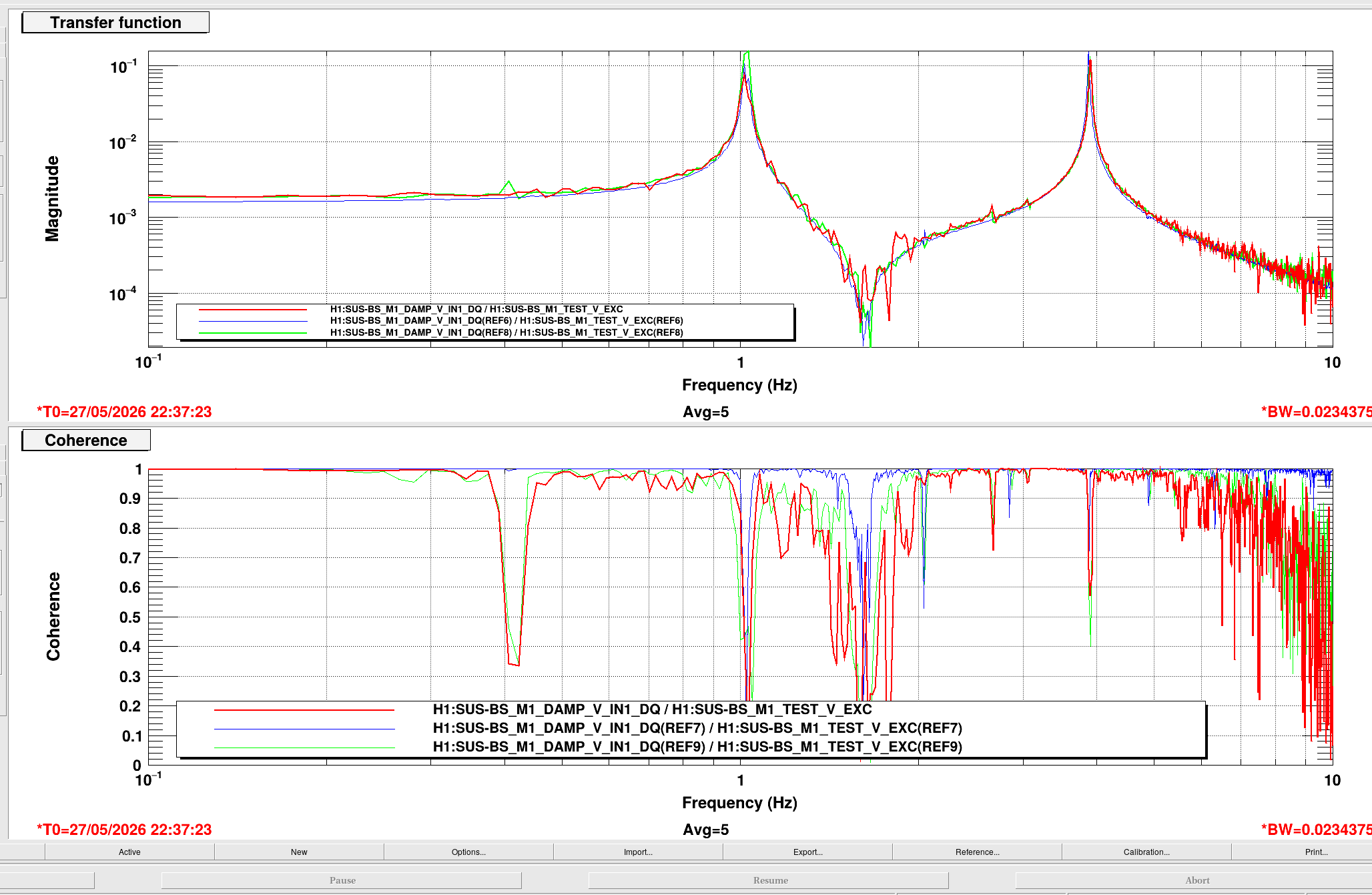
Took a couple transfer functions for T, V, and P to just check on the OSEMs. All three dofs, so all osems, are looking good.

The measurements can be found in /ligo/svncommon/SusSVN/sus/trunk/BBSS/H1/BS/SAGM1/Data/2026-05-27_2200_tfs/2026-05-27_2200_H1SUSBS_M1_WhiteNoise_{T,V,P}_0p02to50Hz.xml and are committed as r13022.

Images attached to this report
H1 General
oli.patane@LIGO.ORG - posted 16:45, Wednesday 27 May 2026 (90361)
Ops DAY Shift End

TITLE: 05/27 Day Shift: 1430-2330 UTC (0730-1630 PST), all times posted in UTC
STATE of H1: Planned Engineering
INCOMING OPERATOR: None
SHIFT SUMMARY: LVEA is LASER SAFE
LOG:

Start Time System Name Location Lazer_Haz Task Time End
13:25 FAC Kim LVEA n Tech clean 13:38
14:38 FAC Kim LVEA n Tech clean 16:37
15:46 SUS Betsy LVEA n Checking out BBSS 15:57
15:49 SEI Jeff Optics lab y(local) SPI work, turn on the laser 15:55
16:08 IAS RyanC, Jason LVEA n BBSS FAROing 19:33
16:13 SUS Ibrahim LVEA n BBSS work 19:17
17:10 SEI Jim MER n Powering on HPI controllers 17:13
17:25 SUS Betsy LVEA n BBSS work 19:04
17:29 SPI Jeff, Jennie OpticsLab y(local) SPI work 19:29
17:52 SEI Jim, Shoshana H2 PSL n CRS build 19:33
18:39 VAC Jordan LVEA n Turning off bakeout 20:03
18:40 VAC Gerardo LVEA n Taking measurements 19:12
19:01   Richard LVEA n Making sure people are working 19:12
19:55 SEI Fil MER n HEPI controller electronics 00:28
20:18 VAC Travis MX, EX n Turbo pump tests 23:12
20:22 SUS Ibrahim, Betsy LVEA n BBSS work (Betsy out 23:24) 23:48
20:30 IAS Jason, RyanC LVEA n BBSS FAROing 23:51
20:36 FAC Randy LVEA n Moving railings 21:11
20:44 TCS Camilla LVEA n Grabbing stuff from TCS cabinets 20:49
20:57 VAC Jordan LVEA n Checking on RGA 21:07
20:59 SEI Jim, Shoshana H2 PSL n CRS work 22:58
22:52 VAC Jordan LVEA n RGA CP1 checks 22:56
23:12 SPI Jennie, Jim OpticsLab y(local) SPI dream team work 00:42
H1 SQZ
sheila.dwyer@LIGO.ORG - posted 14:45, Wednesday 27 May 2026 (90345)
squeezer beam profiles

This is a follow up on 90181.  

Confirming that we understand the profiler data for nominal psams setting, and that the mode has changed

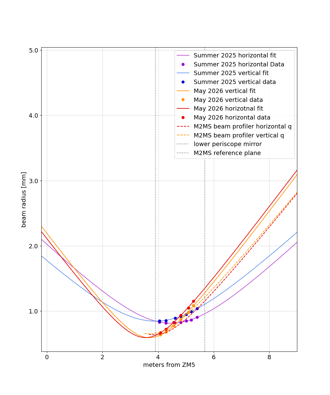
Tony, Ryan Short and I went back onto the floor the week of May 11th.  We followed the alignment procedure for the M2MS profiler extension kit, which did result in different results.  Because we have been confused about how to interpret the results from M2Ms, especially the "Original Waist position" Tony, Ryan and I took a scanning slit profiler out to the table and measured beam diameters at similar locations to where Leo, Camilla and Jennie measured in 85917.  The scanning slit measurements are shown as dots in the attached comparison, each of them is fit by the finesse BeamParamFit shown by the solid line of the same color.  Leo also did a fit to the 2025 data as reported in 86365, the finesse fits have overlaps of 98.7% and 97.5% with Leo's fits.  

The M2Ms profiler reports Rayleigh length, and also "Original Waist position".  From my conversations with tech support I believe that the "Original Waist position" is a distance from the reference plane as shown in this diagram, in mm (they say they will update the software to reflect that it is mm not um), where a positive number means that the waist is on the side of the reference plane closer to the source.  From 90181 I believe that the reference plane is 5.678 meters from ZM5, and all these beams are converging as they leave ZM5, so the real part of q should be negative.  So the real part of the q parameter is -1*(5.678-"Original beam waist position"*1e-3.  )  The dashed lines in the comparison are qs from the M2Ms software, for the M2Ms overlaps with the scanning slit fit by 98.7% (vertical) and 98.9% (horizontal).  

Although the different fitting and measurement types don't exactly agree with each other, the mode is clearly different after the OPO swap, the overlap of the beam width measurements now vs Summer 2025 is 87% for vertical and 85% for horizontal.   In summer 2025 the overlap of the horiztonal mode with the verical mode was 98%, now it is 99.5%.  

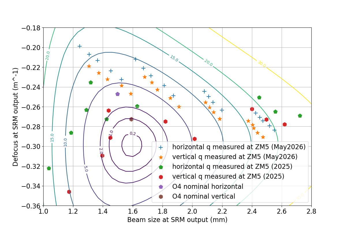
Sw plot for various psams settingsThis plot shows the measured beam parameters, both from this recent data set and from Leo's fits in  86365,propagated to SRM, with contours showing constant mode matching to the OMC for reference.  This can be compared to plots that Evan Hall has made in G2600435.  In O4, this confirms that we our choice for a nominal psams setting did bring us as close to good mode matching to the OMC with the psams that we had, but that we couldn't access the best mode matching parts of the space.  This also confirms that the astimgatism of the squeezer beam would have limited our mode matching if we had been able to move the psams to bring the beam closer to the OMC mode.  

Guess and check for psams actuation strength

Using this May 2026 set of q measurements, I've attempted to check the actuation strength of ZM4+ ZM5 psams.  Since we don't have a measurement of the q before ZM4, we don't actually have information in this dataset about the curvature of ZM4 (we can't distinguish between the curvature of the beam incident on ZM4 with the curvature of ZM4). Alog 90218 summarizes what we expect for the ROC of the psams with 0V applied to the PZT based on the preload that was applied.  I've taken a set of guesses for the ROCs at nominal psams settings, and mD/V for each psams, and used the measured horizontal and vertical q for the nominal psams settings to propagate back to a q incident on ZM4.  Then I propagated that forward for each different psams voltage, to predict the qs and compare to the measured qs in the attached plot.  We have no information about the ZM4 ROC here, since we don't know the curvature of the beam incident on ZM4, so that parameter doesn't matter.  There is also a degeneracy between the nominal ZM5 ROC and the actuation strength of ZM4, they both change the spacing between the group of 5 measurements taken at different ZM4 voltages.  

We can find the nominal psams actuation strengths from E2100288,(we have ZM4 SN1 and ZM5 SN4 at H1), although those measurements were from before the pre-load was changed Camille tells me they should be about the same.  I cannot get a reasonable match to the measured data without reducing the actuation strength of ZM5 to about half of what it should be.  For ZM5 ROC, we can make an estimate based on 90186 and the nominal -0.58mD/V pzt reponse that the nominal ROC should be around 3meters, this doesn't seem to give us a good match to the measured q parameters.  

This is a follow up on 90181.  

Confirming that we understand the profiler data for nominal psams setting, and that the mode has changed

Tony, Ryan Short and I went back onto the floor the week of May 11th.  We followed the alignment procedure for the M2MS profiler extension kit, which did result in different results.  Because we have been confused about how to interpret the results from M2Ms, especially the "Original Waist position" Tony, Ryan and I took a scanning slit profiler out to the table and measured beam diameters at similar locations to where Leo, Camilla and Jennie measured in 85917.  The scanning slit measurements are shown as dots in the attached comparison, each of them is fit by the finesse BeamParamFit shown by the solid line of the same color.  Leo also did a fit to the 2025 data as reported in 86365, the finesse fits have overlaps of 98.7% and 97.5% with Leo's fits.  

The M2Ms profiler reports Rayleigh length, and also "Original Waist position".  From my conversations with tech support I believe that the "Original Waist position" is a distance from the reference plane as shown in this diagram, in mm (they say they will update the software to reflect that it is mm not um), where a positive number means that the waist is on the side of the reference plane closer to the source.  From 90181 I believe that the reference plane is 5.678 meters from ZM5, and all these beams are converging as they leave ZM5, so the real part of q should be negative.  So the real part of the q parameter is -1*(5.678-"Original beam waist position"*1e-3.  )  The dashed lines in the comparison are qs from the M2Ms software, for the M2Ms overlaps with the scanning slit fit by 98.7% (vertical) and 98.9% (horizontal).  

Although the different fitting and measurement types don't exactly agree with each other, the mode is clearly different after the OPO swap, the overlap of the beam width measurements now vs Summer 2025 is 87% for vertical and 85% for horizontal.   In summer 2025 the overlap of the horiztonal mode with the verical mode was 98%, now it is 99.5%.  

Sw plot for various psams settingsThis plot shows the measured beam parameters, both from this recent data set and from Leo's fits in  86365,propagated to SRM, with contours showing constant mode matching to the OMC for reference.  This can be compared to plots that Evan Hall has made in G2600435.  In O4, this confirms that we our choice for a nominal psams setting did bring us as close to good mode matching to the OMC with the psams that we had, but that we couldn't access the best mode matching parts of the space.  This also confirms that the astimgatism of the squeezer beam would have limited our mode matching if we had been able to move the psams to bring the beam closer to the OMC mode.  

Guess and check for psams actuation strength

Using this May 2026 set of q measurements, I've attempted to check the actuation strength of ZM4+ ZM5 psams.  Since we don't have a measurement of the q before ZM4, we don't actually have information in this dataset about the curvature of ZM4 (we can't distinguish between the curvature of the beam incident on ZM4 with the curvature of ZM4). Alog 90218 summarizes what we expect for the ROC of the psams with 0V applied to the PZT based on the preload that was applied.  I've taken a set of guesses for the ROCs at nominal psams settings, and mD/V for each psams, and used the measured horizontal and vertical q for the nominal psams settings to propagate back to a q incident on ZM4.  Then I propagated that forward for each different psams voltage, to predict the qs and compare to the measured qs in the attached plot.  We have no information about the ZM4 ROC here, since we don't know the curvature of the beam incident on ZM4, so that parameter doesn't matter.  There is also a degeneracy between the nominal ZM5 ROC and the actuation strength of ZM4, they both change the spacing between the group of 5 measurements taken at different ZM4 voltages.  

We can find the nominal psams actuation strengths from E2100288,(we have ZM4 SN1 and ZM5 SN4 at H1), although those measurements were from before the pre-load was changed Camille tells me they should be about the same.  I cannot get a reasonable match to the measured data without reducing the actuation strength of ZM5 to about half of what it should be.  For ZM5 ROC, we can make an estimate based on 90186 and the nominal -0.58mD/V pzt reponse that the nominal ROC should be around 3 meters, this doesn't seem to give us a good match to the measured q parameters.  

The scripts used to make these plots are available here: plot_dataset_May2026.py and compare_summer_2025_to_may2026.py I've also uploaded the conversation with Thorlabs tech support T2600231

Images attached to this report
H1 ISC (INS, IOO, ISC)
keita.kawabe@LIGO.ORG - posted 13:45, Wednesday 27 May 2026 - last comment - 13:46, Wednesday 27 May 2026(90343)
IM4 beam position (Rahul, Elenna, Keita)

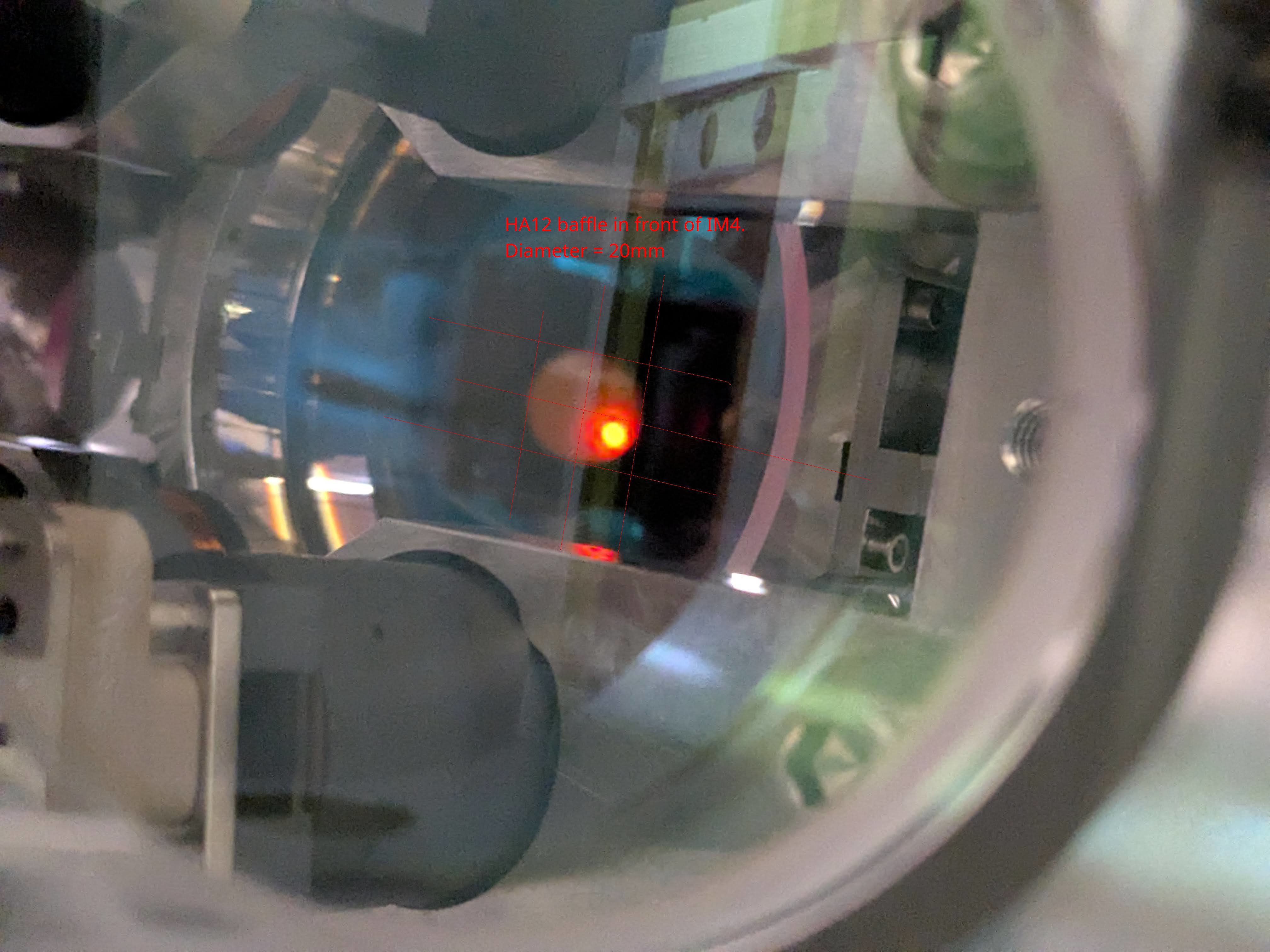
IM4 (and IM4 baffle) beam position

This is a belated alog from Tuesday.

Starting point: Same alignment for MC123, IM123 as last Friday, i.e. the IM4 baffle NOT centered nor unclipped.

Without touching IMC and IM1/2/3, we rotated IM4 to steer the beam close enough to the nominal beam position in front of PR2, and measured the beam position horizontally and vertically relative to the known screw hole in front of PR2 and PRM.

The distance between IM4-PRM beam line as of now relative to the nominal PRM-PR2 center line was calculated to be 3.9+-1.1mm in -Y direction and too low by 2.9+-1.1mm. See measurement_cartoon.jpg for the horizontal position case. Height is derived in the same way. Since the beam position in front of PR2 is not grossly off, and since IM4 is much, much closer to PRM than PR2, you can use these numbers as the spot position on PRM, too.

From IM4baffle_20260526.jpg, centering the beam on PRM will correct the height on IM4 baffle (HA12). Horizontally it will within a couple mm or so from the center.

What we should do

As we're running out of time, give up the idea to understand what happened to the alignment during the vent before closing HAM2. We should recenter things whenever possible (but only when the IFO REFL path and POP sled path are not disturbed to the point we clip or lose the beam).

For IMC, 


For IMs,

following is the table of slider offsets as of now.

  IM1 IM2 IM3 IM4
PIT 517 810 -614 531
YAW -387 -88 385 64

Even though the physical PIT angle of the optics relative to the local vertical axis is arbitrary, it seems that IM1 is bringing the beam down on IM2, IM2 is bringing down the beam further on IM3, and IM3 is bringing up the beam on IM4 and PRM. But IM2 is twise as efficient as IM3 for changing the beam position on PRM. Besides, the beam is already coming down from MC2 to MC3 (about 10mm height difference over 16m, or about 220urad) and I don't know if it makes sense to use IM2 to bring the beam further down. It's worth redistributing PIT as well as YAW offsets to relieve big offsets.

However, note that ultimately IM1-IM2 line defines the IFO REFL path when PRM retroreflects. (Even if you rotate IM2, as far as IM1-IM2 line doesn't change the IFO refl beam won't move.) I won't touch IM1 as moving the beam on e.g. IM2 even just a few mm using IM1 (i.e. a few mm over ~1.8m leverarm) will result in a much bigger change for REFL path in HAM1, potentially risking yet another clipping or maybe the loss of the REFL beam. IMC alignment noted above will change the IM1-IM2 line, but that's basically the angle change of ~3.6mm/16m (i.e. an order of magnitude smaller than when moving IM1 to steer the beam on IM2 in a meangful amplitude). That's small enough it's hard to imagine that the beam will be clipped by IFO refl baffle nor the downstream optics.

So,

PIT

IM2 IM3 IM4 PRM
IM2 (810 -> 310, negative 500urad)  0 1.2 +2.8 +3.5mm
IM3 (-614.7 -> -434.7, positive 180urad)     -0.4 -0.6mm
Total change   1.2 2.4 2.9mm (higher)
Position as of now       -2.9mm (too low)


YAW IM2 IM3 IM4 PRM
From MC2 beam spot change

0.4mm (-X)

0.6mm (-X) 1mm (-X) 1.2mm (+Y)
IM2 (-88 -> 112urad, positive 200urad change)   0.5mm (-X) 1.1mm (-X) 1.4mm (+Y)
IM3 (385urad -> 0, negative 385 urad change)     0.9mm (-X) 1.3mm (+Y)
Total change 0.4mm (-X) 1.1mm (-X) 3mm (-X) 3.9mm (+Y)
Position as of now       3.9mm (-Y)

 Of course this is assuming that the slider calibration is correct, so take this as a qualitative reference to get the sense of sign of angle changes. Anyway, when this is done, the DAC counts for IM2 and IM3 will be smaller while the beam height on PR2 will be fine. 

  IM1 (no touch) IM2 IM3 IM4
PIT 517 810-> 310 -614-> -434.7 531-> ?
YAW -387 -88-> 112 385-> 0 64-> ?

After doing the above,

If centering HA12 (IM4) baffle is important, relocate HA12. I'll ask Rodica.

Make sure that PRM retroreflects. Readjust if not. Check IFO REFL beam on IFO REFL baffle, LSC REFL and ASC REFL sensors. 

Recenter IM4_TRANCE by pico. 

Realign ISS array (simply because it's easier to do it in air than in vacuum).

Homework

Think about POP sled path. Is it conceivable that we'll somehow miss the beam there because we change the beam spot position on PRM?

Images attached to this report
Comments related to this report
keita.kawabe@LIGO.ORG - 13:46, Wednesday 27 May 2026 (90360)

These pictures explain the horizontal beam position measurement in detail.

Images attached to this comment
H1 PSL
ryan.short@LIGO.ORG - posted 13:32, Wednesday 27 May 2026 (90359)
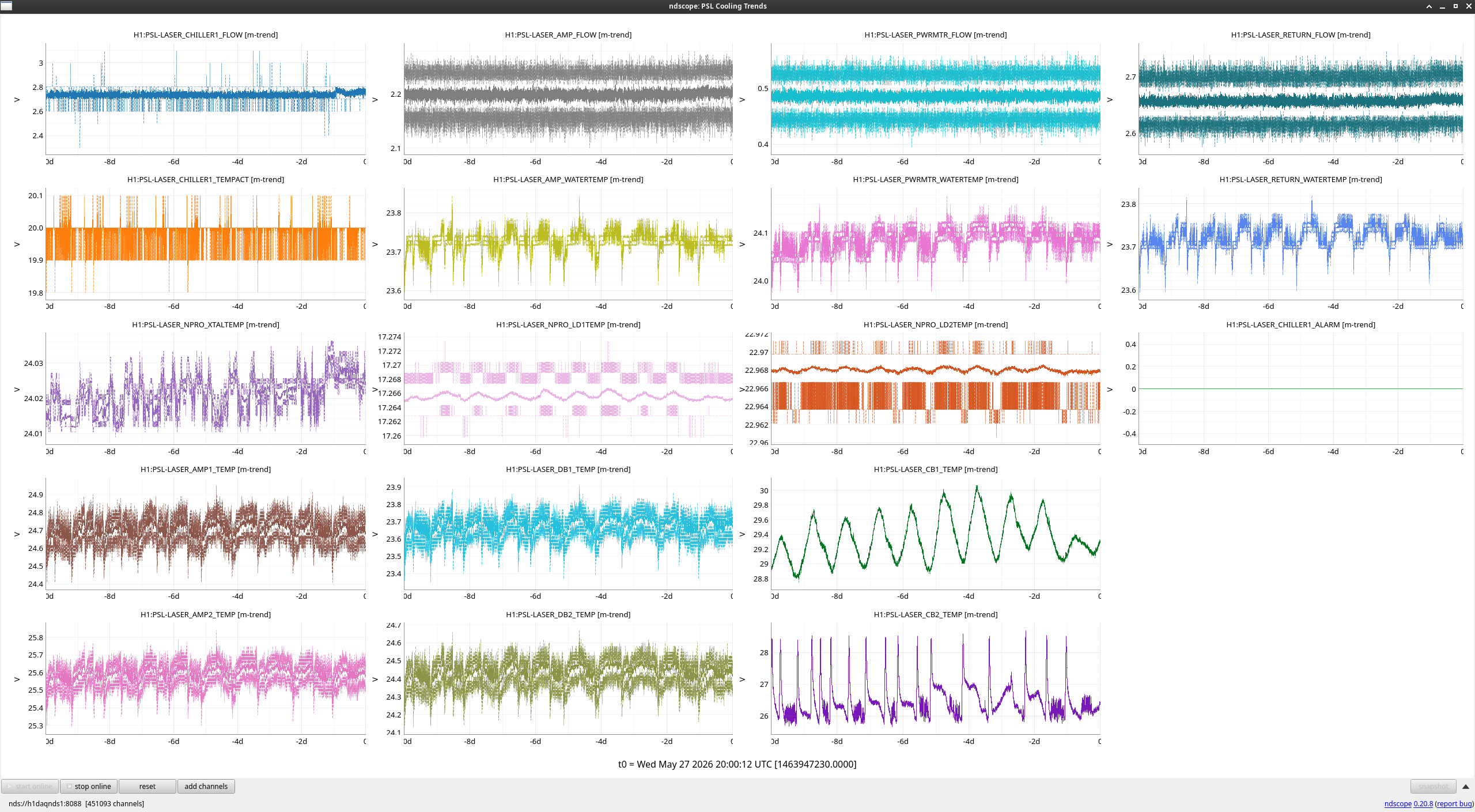
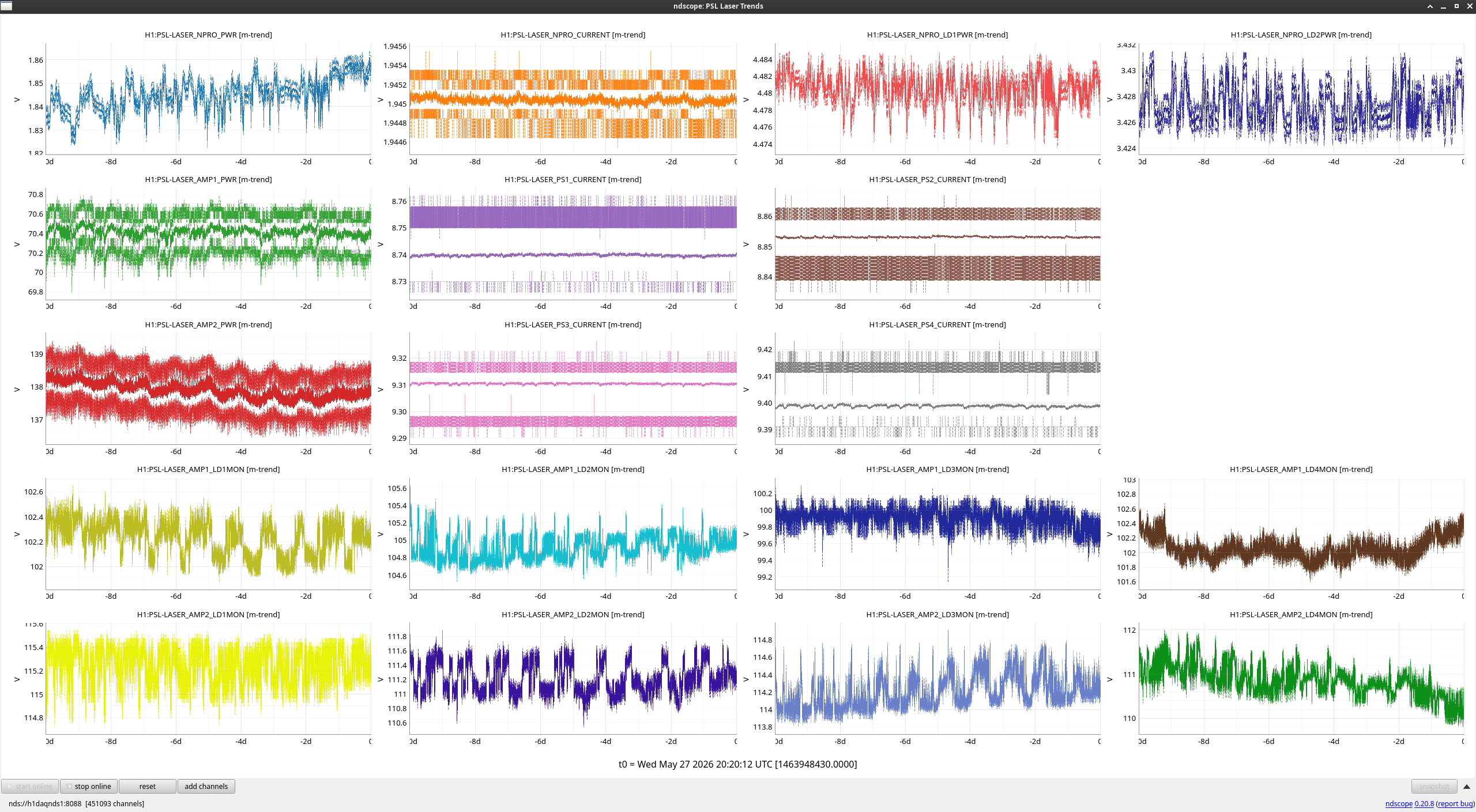
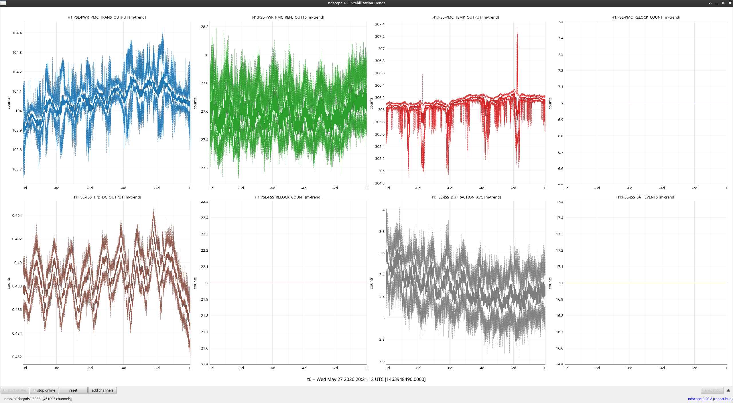
PSL 10-Day Trends

FAMIS 63900

No major events of note this week.

Images attached to this report
H1 SPI
joshua.freed@LIGO.ORG - posted 11:46, Wednesday 27 May 2026 (90352)
SPI, RF Install Pt3, Phase noise

J. Freed

Update from last time 90273:

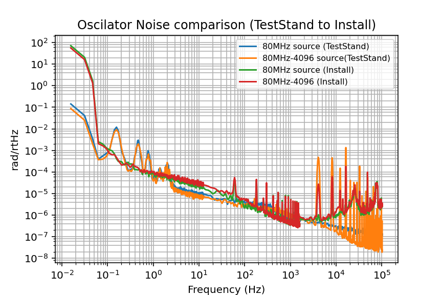
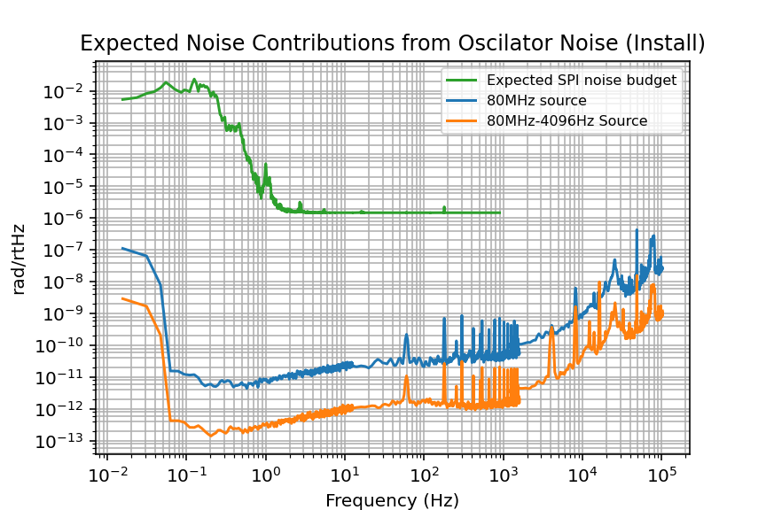
I took phase noise (PN) measurements of the SPI RF chain yesterday and found that nothing drastically changed in performance from test stand set up to final set up DM_Install.png. And that Oscillator noise is not a noise limit for SPI DM_Install2.png (The shape changed is calculated by the same equation as 88457) Note that PN measurments can be limited by the reference frequency. As such, the plots of PN are plotting a maximum noise. The actual noise could be even less (see notes).

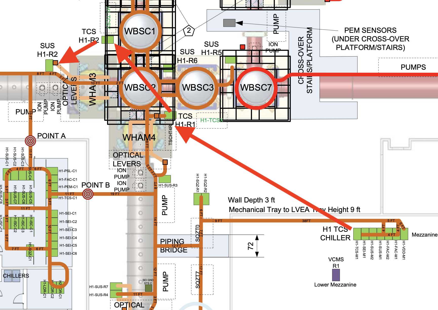
The main thing a phase noise set up needs is a reference signal with the same frequency as the RF signal being tested with good performance. An OCXO that is timing locked to LIGOs 1pps timing signal or a frequency generator that is locked to a 10MHz signal produced by that OCXO is required. Where to get this specific requirement in the LVEA? J. Kissel gave the idea to use the Frequency generator that produces the TCS 40.68MHz signal to be delivered to the TCS-R2 rack about 12ft away from SUS-R2. 

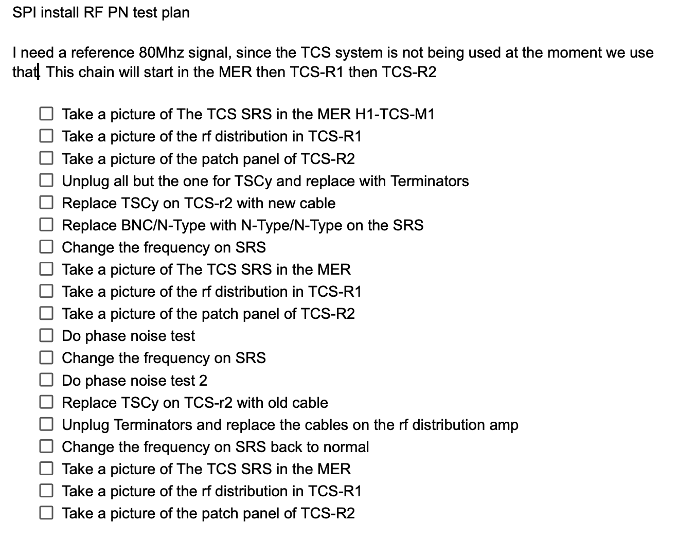
SPI_PN_layout.png Shows the layout of this set up. A 40.68MHz signal is produced in the MER TCS-M1 rack by a SRS SG382 function generator Screenshot2026-05-27at103451 AM.png. Where it is sent to the LVEA rack TCS-R1. The signal then is sent into an RF distributor Screenshot2026-05-27at103458 AM.png where it is split into signals for TCSx, TCSy, and a mon channel. TCSy is then sent to TCS-R2 Screenshot2026-05-27at103806 AM.png. I could then run a long cable to SUS-R2 from TCS-R2 Screenshot2026-05-27at103523 AM.png and by adjusting the frequency of the frequency generator so I could perform the PN test. Before switching the frequency on the SRS, I made sure to replace the wires in TCS-R1 going to TCSx and the mon channel with terminators and replace the wire going to TCSy in TCS-R2 with my own long cable. I then did the reverse order to put TCS back. (SPI_Install_PN_TestPlan.png is the plan I followed.)


Notes: 

The TCS SRS SG382 function generator N-Type Connector is burnt out. I cannot find a report on this but will add a comment if that changes

The SRS SG382 function generator has 2 ports, a BNC and a N-type. The BNC typically handles lower power and lower frequency while the N-type handles higher power and higher frequency. The 40.68MHz nominal signal can go through either port while the 80MHz I need for the PN test must go through the N-Type port. This means the PN measurements I took went through the burnt out N-type. 

I confirmed this by checking the power of the signal at sus R2, then by only changing the port, checked the power again. With the nominal 40.68MHz signal outputted at 13dBm from the TCS function generator BNC Port. I measured 11.2dBm at SUS-R2. By only swiching to the N-type port, I measured -18dBm. A ~30dBm drop. Technically I also switched out a cable from BNC/N-Type to N-type/N-type so I checked that too by using another N-Type/N-type and there was no change in power between cables. 

This did not seem to have a drastic effect on the PN measurements except for a slightly higher general noise floor and alot of noise at high frequency which SPI is insensitive to. This has no effect on the conclusion that Oscillator noise is not a noise limit for SPI.

Images attached to this report
H1 SUS
oli.patane@LIGO.ORG - posted 10:21, Wednesday 27 May 2026 (90356)
BBSS test stand TFs after some FARO alignment

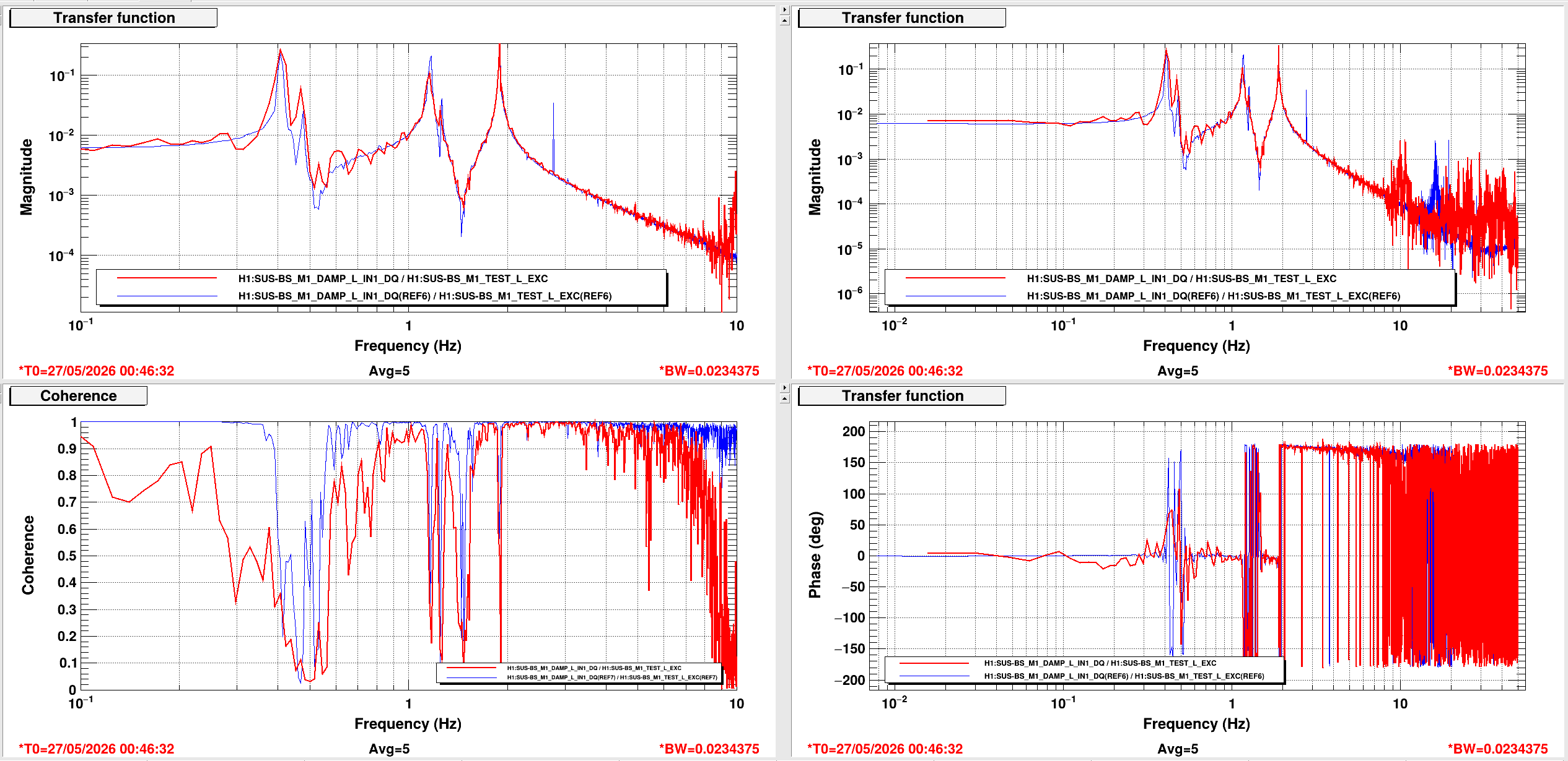
After figuring out the damping issues for the BBSS yesterday (90341), we took some transfer functions to check for rubbing or anything else weird after all the alignment work that has been occurring.

These measurements were taken using BOSEMs, and have the correct DAC compensation value of gain(4096) in the COILOUTF filter bank.

Data
/ligo/svncommon/SusSVN/sus/trunk/BBSS/H1/BS/SAGM1/Data/2026-05-26_1700_tfs/2026-05-26_1700_H1SUSBS_M1_WhiteNoise_{L,T,V,R,P,Y}_0p02to50Hz.xml
r13020
Results
/ligo/svncommon/SusSVN/sus/trunk/BBSS/H1/BS/SAGM1/Results/2026-05-26_1700_tfs/2026-05-26_1700_H1SUSBS_M1_ALL_TFs.pdf
r13021

Images attached to this report
Non-image files attached to this report
H1 General
oli.patane@LIGO.ORG - posted 07:37, Wednesday 27 May 2026 - last comment - 10:02, Wednesday 27 May 2026(90349)
Ops DAY Shift Start

TITLE: 05/27 Day Shift: 1430-2330 UTC (0730-1630 PST), all times posted in UTC
STATE of H1: Planned Engineering
OUTGOING OPERATOR: None
CURRENT ENVIRONMENT:
    SEI_ENV state: MAINTENANCE
    Wind: 8mph Gusts, 5mph 3min avg
    Primary useism: 0.06 μm/s
    Secondary useism: 0.23 μm/s 
QUICK SUMMARY:

The LVEA is LASER SAFE

Comments related to this report
oli.patane@LIGO.ORG - 08:18, Wednesday 27 May 2026 (90350)VE

Ryan C, Oli

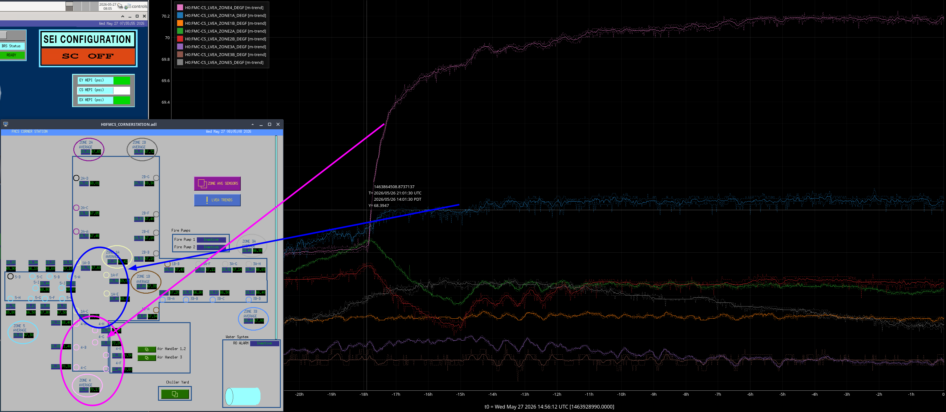
Temps have been going up in the LVEA due to the HAM4 and HAM6 RGA high temp bakeout that is currently happening (WP13214). Zone 4 (output arm) is by far the most affected, but it looks like the temps there are leveling off just above 70 F and holding their own against the bakeout temperatures.

Images attached to this comment
betsy.weaver@LIGO.ORG - 10:02, Wednesday 27 May 2026 (90355)

Also - Late alog:  Yesterday we flipped on the HAM567 Mega cleanroom fans to get the room cleaned up in prep for opening HAM7.  This likley is raising the temp in that zone.  Sheila is aware that this may effect suspensions.

H1 General
oli.patane@LIGO.ORG - posted 16:37, Tuesday 26 May 2026 - last comment - 10:01, Wednesday 27 May 2026(90347)
Ops DAY Shift End

TITLE: 05/26 Day Shift: 1430-2330 UTC (0730-1630 PST), all times posted in UTC
STATE of H1: Planned Engineering
INCOMING OPERATOR: None
SHIFT SUMMARY: Work continued today in HAM2 and currently there is still work going on at the test stand on the BBSS.

The LVEA is currently LASER SAFE


LOG:

Start Time System Name Location Lazer_Haz Task Time End
14:30 FAC Kim LVEA n Tech clean 16:04
14:45 SUS Betsy LVEA n BBSS work 16:23
14:52 FIT Patrick XARM n Leisurely strolling 15:50
15:08   Richard LVEA n Catching Betsy 15:21
16:05 SUS Ibrahim LVEA n BBSS work 16:23
16:05 TCS Camilla JOAT Lab n CHETA work 17:14
16:05   Keita LVEA n Talking to Betsy 16:23
16:13 IAS Jason, RyanC LVEA YES FAROing BBSS 18:06
16:16 VAC Travis LVEA n Checking on pumps 16:27
16:50 FAC Chris, pest guy LVEA YES Spraying the little guys 17:04
16:56 ISC Keita, Rahul LVEA YES ISS Array work 18:52
17:06 SPI Marc, Josh LVEA YES SPI cabling (Marc out 17:10) 17:50
17:17 FAC Eric Fire pump room n Testing fire pumps 17:48
17:22 ISC Elenna LVEA YES ISS work 18:51
16:50 FAC Chris, pest guy LVEA YES Spraying the little guys 17:04
17:58 SPI Josh LVEA, MER n SPI cabling 23:34
18:00 FAC Kim FCES N Technical Cleaning 18:41
18:36   Corey OpticsLab n   19:22
19:03 HAZ Keita LVEA YES Transitioning LVEA back to laser SAFE 19:09
19:53 SUS Betsy LVEA n BBSS work ongoing
20:09 IAS Jason, RyanC LVEA n FAROing BBSS ongoing
20:26 SPI Jeff OpticsLab y(local) SPI work ongoing
20:39 CRS Shoshana, Jim H2 PSL n CRS build 22:07
20:42 EE Fil LVEA n Grabbing measurements by TCS racks 23:28
20:54 SUS Ibrahim LVEA n BBSS work ongoing
21:02   Camilla OpticsLab y(local) Bringing beam scanner to Jeff 21:21
21:28 VAC Gerardo LVEA n Checking out roasting HAMs 21:46
22:31 CRS Shoshana H2 PSL n CRS work ongoing
Comments related to this report
betsy.weaver@LIGO.ORG - 10:01, Wednesday 27 May 2026 (90354)

Late alog:  Yesterday we flipped on the HAM567 Mega cleanroom fans to get the room cleaned up in prep for opening HAM7.  This likley is raising the temp in that zone.  Sheila is aware that this may effect suspensions.

ryan.crouch@LIGO.ORG - 17:34, Tuesday 26 May 2026 (90348)PEM

ZONE4's temperature has increased by almost 2 degrees since 21:00 UTC (2pm PDT).

Images attached to this comment
H1 SUS
jeffrey.kissel@LIGO.ORG - posted 12:06, Tuesday 26 May 2026 - last comment - 10:23, Wednesday 27 May 2026(90341)
Debugging BBSS Damping Loops
J. Kissel, O. Patane, B. Weaver, I. Abouelfettouh

Executive Summary: For now, we can damp the BBSS Glass BS with BOSEMs and old Level 2 BSFM Glass BS damping loops as long as the L and P EPICs gains are -0.5, all other DOFs are -1.0, and we turn OFF all DOFs of the BSFM bounce/roll mode notches.

Debugging damping loops for BBSS with BOSEMs mounted to the table cloth, we found that with direct copy of "old" level 2 damping loops for BS (a BSFM) was unstable, ringing up in L and P at 2.668 Hz (measured with t-cursors on an ndscope session). 

This is not a huge surprise; we'd already modeled the phase margin with this direct copy SWG:12301 has very low phase margin (modeled to be 23.8 [deg], with the highest upper unity gain frequency crossing at ~2.5 Hz; see dampingfilters_BBSS_2025-07-09.pdf page 33). Plus, experience has taught us that measured TFs often have more phase loss than models, so the phase margin of the loops is likely even less -- hence instability from 1/(1+G) gain peaking.

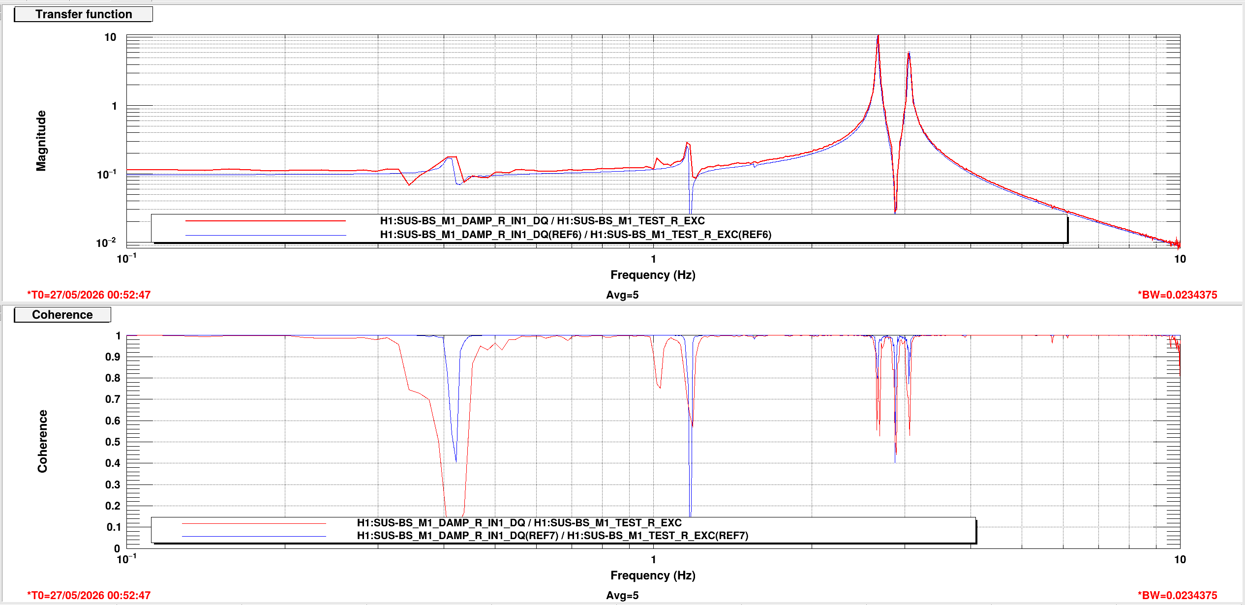
Ibrahim took some preliminary undamped TFs to confirm the (undamped) dynamical TFs of the BBSS with a glass optic. With what poor coherence we have in air, we can at least eye-ball confirm that they're not substantially different from the metal build on the test stand. Good! Great! We'll try to get these TFs better and Ibrahim will post for reference.

OK, with the dynamics checked out, on to the damping loops. Thus far the team had just rammed all the Level 2 BSFM loops on with a gain of -1.0, as we'd run them for years with the BSFM BS.

So, we did the dumb things first: 
    - We turned OFF the BSFM's BS highest bounce ("SB17.79" FM8) and roll ("SB26.06" FM9) mode frequency notch filters. We know these are the wrong frequency, and they're just eating up phase. (We plotted them, and it's not much at ~2 Hz, but they're the wrong frequency for a BBSS, so we just turned them OFF.) 
    - Turned on DOFs one or two at a time to narrow down which DOF(s) are problematic. T, V, R, and Y close fine and are stable with the old BSFM filters with a gain of -1.0. L and P are the loops that buzz at the 2.625 Hz (0.005 Hz resolution ASD with DTT).
    - Just reduce the overall gain of the loop(s) -- tried P at -0.5 and -0.25 with L still at -1.0. That was still unstable. But, L, P = -0.5, -0.5, is nicely stable, and damps stuff.

Getting slightly smarter, we checked in with the hard work of Vlad from LHO:81178 and found that the L and P filters have an EPICs gain of -1.0, and are identical in frequency response -- but the *filter* overall gain is a factor of 1.88x lower (i.e. essentially a factor of 2.0x). So -- he had to do essentially the same thing we did (though if I know Vlad, he actually measured this factor of 1.88x rather than blind guess like we did). Note that LLO's already using QOSEMs.

So, for now, we have something stable. Over time, we'll work on improving it, but this'll do. Once we have time, we'll take open loop gains, see exactly where we need phase, and adjust. Smart: Shouldn't need that much, change honestly. 
Just as I said in the acceptance review; Slides 33 and 34 of E2500057, we can easily relax the P low-pass filter and then regain the on-resonance pitch damping that we lost from dropping the overall gain by 2.0x.
Comments related to this report
oli.patane@LIGO.ORG - 16:29, Tuesday 26 May 2026 (90346)

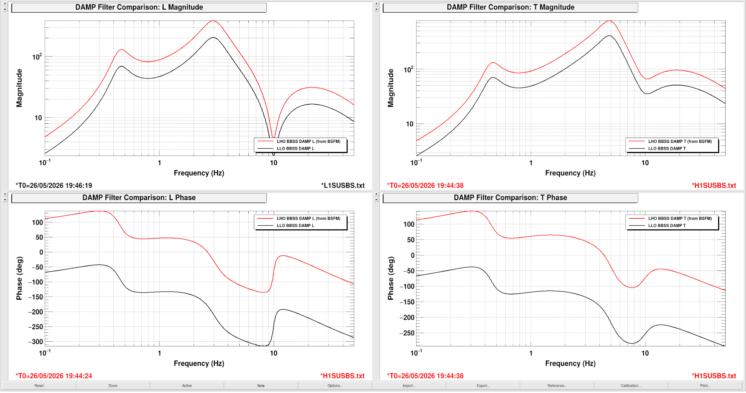
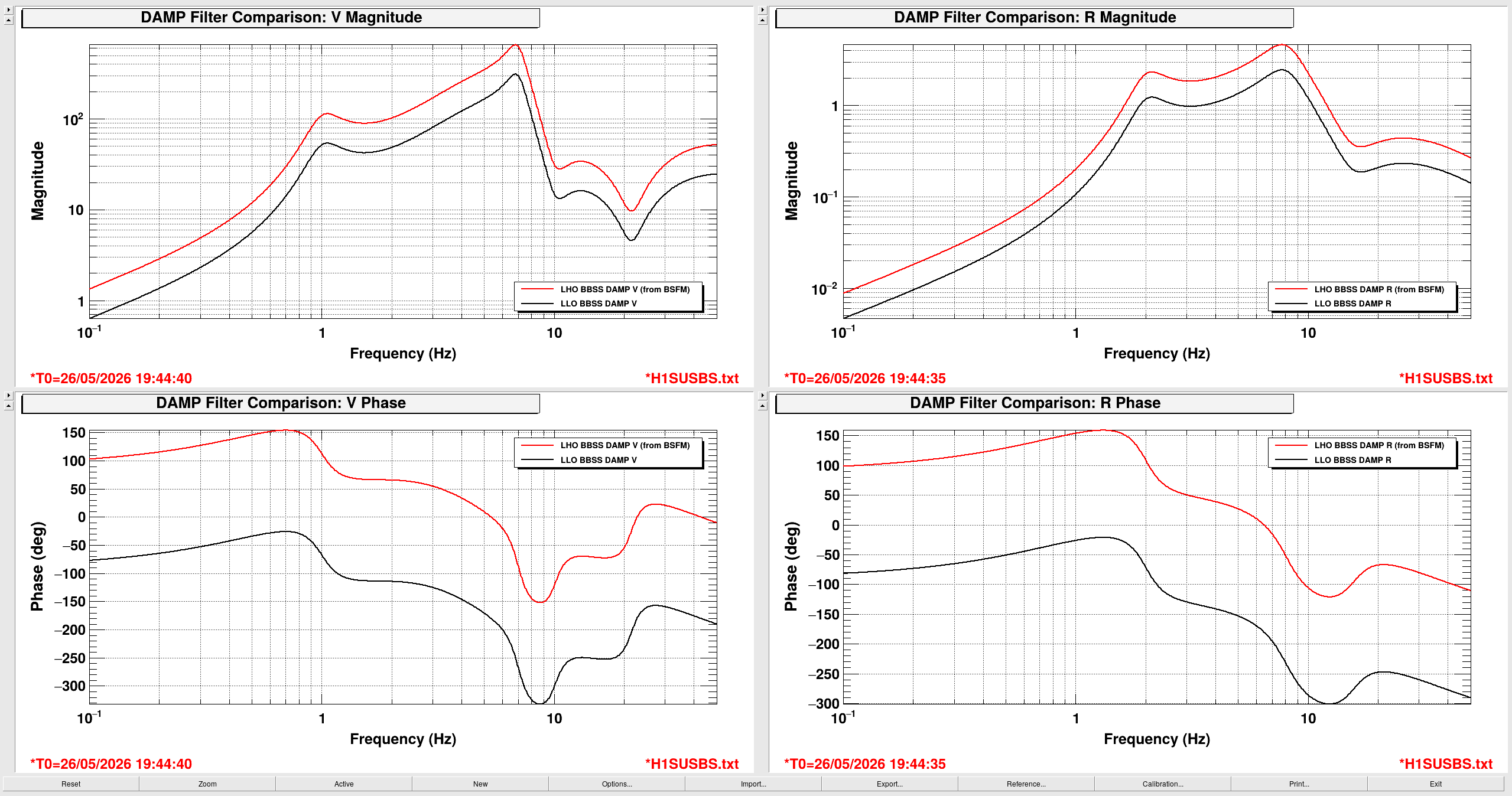
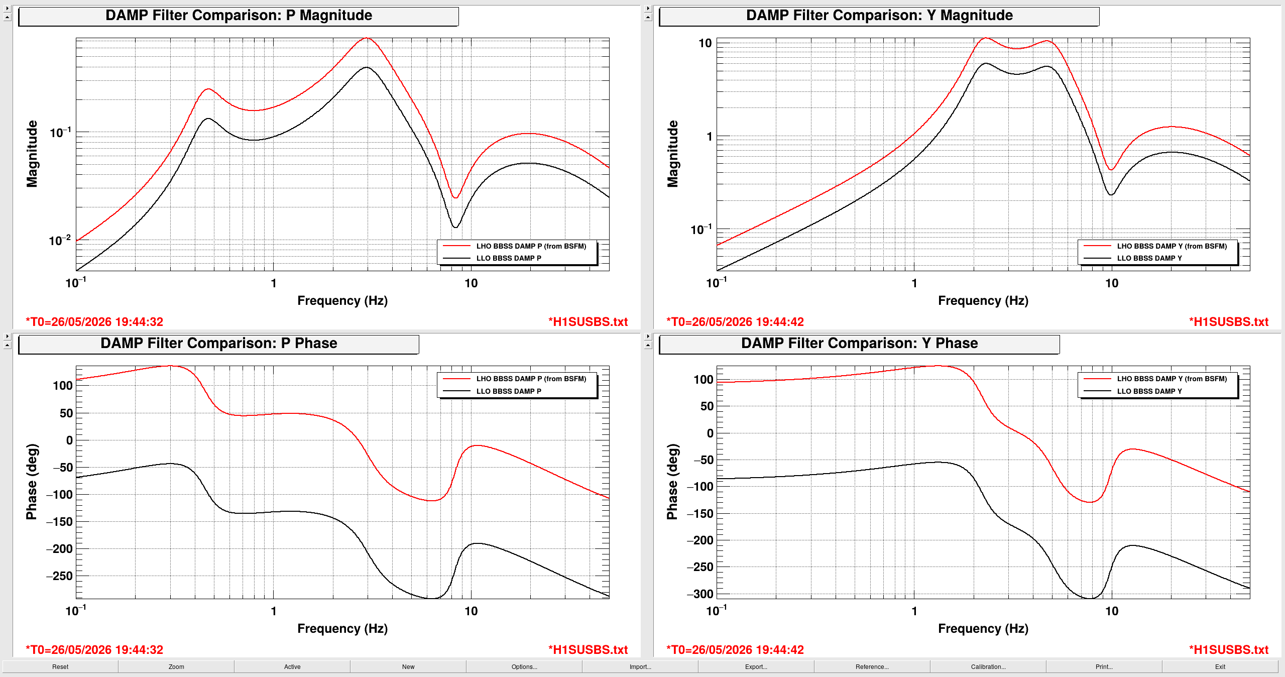
Adding in comparison plots between LLO an LHO's current beamsplitter damping configurations. Like Jeff said, LLO's damping loops have a factor of 1.8 less gain than ours, and that's true for all degrees of freedom (L&T, V&R, P&Y).

I also took a closer look at each site's filters for subtle differences between the sites (table), and it looks like the main difference is gains, which makes sense considering what we can tell right away from looking at the plots.

Images attached to this comment
Non-image files attached to this comment
oli.patane@LIGO.ORG - 09:27, Wednesday 27 May 2026 (90351)

Another quick note: currently on the test stand, the normal breathing frequencies of the BBSS seem to be:
L, T, R, P, Y:    0.4 Hz
V: 1.05 Hz

oli.patane@LIGO.ORG - 10:23, Wednesday 27 May 2026 (90357)

Transfer functions taken after this debugging are in 90356

Images attached to this comment
H1 SUS
oli.patane@LIGO.ORG - posted 15:19, Friday 22 May 2026 - last comment - 09:58, Wednesday 27 May 2026(90323)
BBSS test stand transfer functions

On May 19th, 2026, we took our first set of transfer functions for the BBSS after swapping in the glass optic. They all came out looking good, albiet very noisy because the suspension wasn't covered.

Comparing them to the last measurement we did in the staging building, the peaks still all match up well. There is just a consistance difference in magnitude, but that is probably just due to the difference in electronics between the QUAD stand in the staging building and the BS electronics in the LVEA.

Data
/ligo/svncommon/SusSVN/sus/trunk/BBSS/H1/BS/SAGM1/Data/2026-05-19_2000_tfs/2026-05-19_2000_H1SUSBS_M1_WhiteNoise_{L,T,V,R,P,Y}_0p02to50Hz.xml
r13018
Results
/ligo/svncommon/SusSVN/sus/trunk/BBSS/H1/BS/SAGM1/Results/2026-05-19_2000_tfs/2026-05-19_2000_H1SUSBS_M1_ALL_TFs.pdf
r13018
/ligo/svncommon/SusSVN/sus/trunk/BBSS/Common/Results/allbbss_May2026_BBSS_teststand_vs_staging/allbbsss_May2026_BBSS_teststand_vs_staging_ALL_TFs.pdf
/ligo/svncommon/SusSVN/sus/trunk/BBSS/Common/Results/allbbss_May2026_BBSS_teststand_vs_staging/allbbsss_May2026_BBSS_teststand_vs_staging_ALL_ZOOMED_TFs.pdf
r13017

Images attached to this report
Non-image files attached to this report
Comments related to this report
oli.patane@LIGO.ORG - 09:58, Wednesday 27 May 2026 (90353)

These measurements were taken with BOSEMs. The extra factor of ~4 that these measurements are lower by as compared to the older staging building trace is due to electronics. The BSFM was moved from 18- to 28-bit DACs back in January, so I compensated for this change in the COILOUTF filter bank by adding a filter module with a gain of 1024. However, the BBSS measurements made in the staging building were using a 16-bit DAC, so when we moved the BBSS onto the BSFM system, there was a factor of four of drive missing from excitations, hence these measurements looking lower as compared to the measurements in the staging building. That was remedied after this.

H1 IOO (INS, IOO, ISC)
keita.kawabe@LIGO.ORG - posted 17:29, Thursday 21 May 2026 - last comment - 11:25, Thursday 28 May 2026(90295)
Beam positions in HAM2 and some thinking (Rahul, Elenna, Keita)

(I learned from T0900486 "IO Stray Light Analysis and Baffle Design" that the IFI input baffle is called HA3, IFI output baffle is HA6, the baffle right in front of IM4 is actually supposed to be a pair of HA12-a and HA12-b but there's only one baffle which I suppose is HA12-a, two-hole baffle for ISS array is HA11, and the last IFO REFL before the beam leaves HAM2 is HA13.)

Clipping on the IFI input baffle (HA3) might not be real

The beam spot on this baffle was OK before we did anything to IM1 on Tuesday (IFIinput_before.jpg). It's low and toward +X, but nowhere near clipping.

This baffle is right in front of the calcite wedge that deflects the IFO REFL beam away from the incoming beam path from IM2 (HA3_calcite_wedge.png). The lever arm from the wedge to the baffle looks to be an inch or so at most. Hard to imagine that the REFL is clipped while forward going beam is not, but the scattering goes away when I block the beam between PRM and IM4.

The reported "IFO REFL beam clipping" on this baffle is either because the PRM is not retroreflecting, or maybe it's some kind of ghost beam produced from the PRM reflection somewhere.

If we establish that the main IFO refl is NOT clipped when PRM retroreflects, we don't have to worry about this baffle too much (though ghost beam is still a problem).

We will have to bring a card with a hole to make sure that the beam is retroreflected as good as we can.

FYI, IFIinput_aftercentering.jpg shows the same baffle after we made a huge change in IM1.

We THINK that the beam on the IFI output baffle (HA6) is OK too but we need to check

We don't have any good view of that baffle so it's hard to assess, and we forgot to check it before making changes to IM123.

However, given how small the change was on IFI input baffle, we don't expect that it was very bad before. We'll have to revisit and confirm.

IMC beam spots

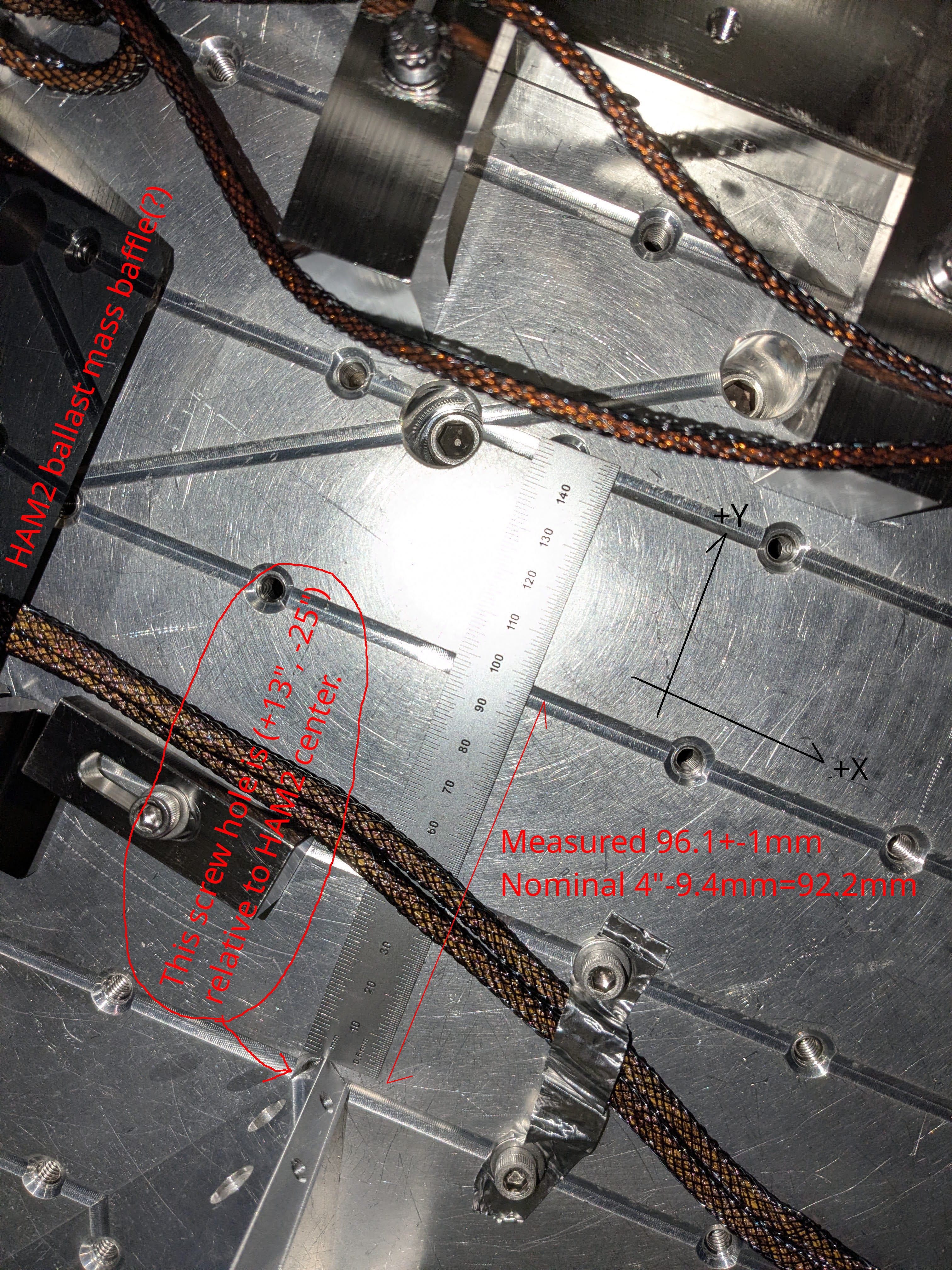
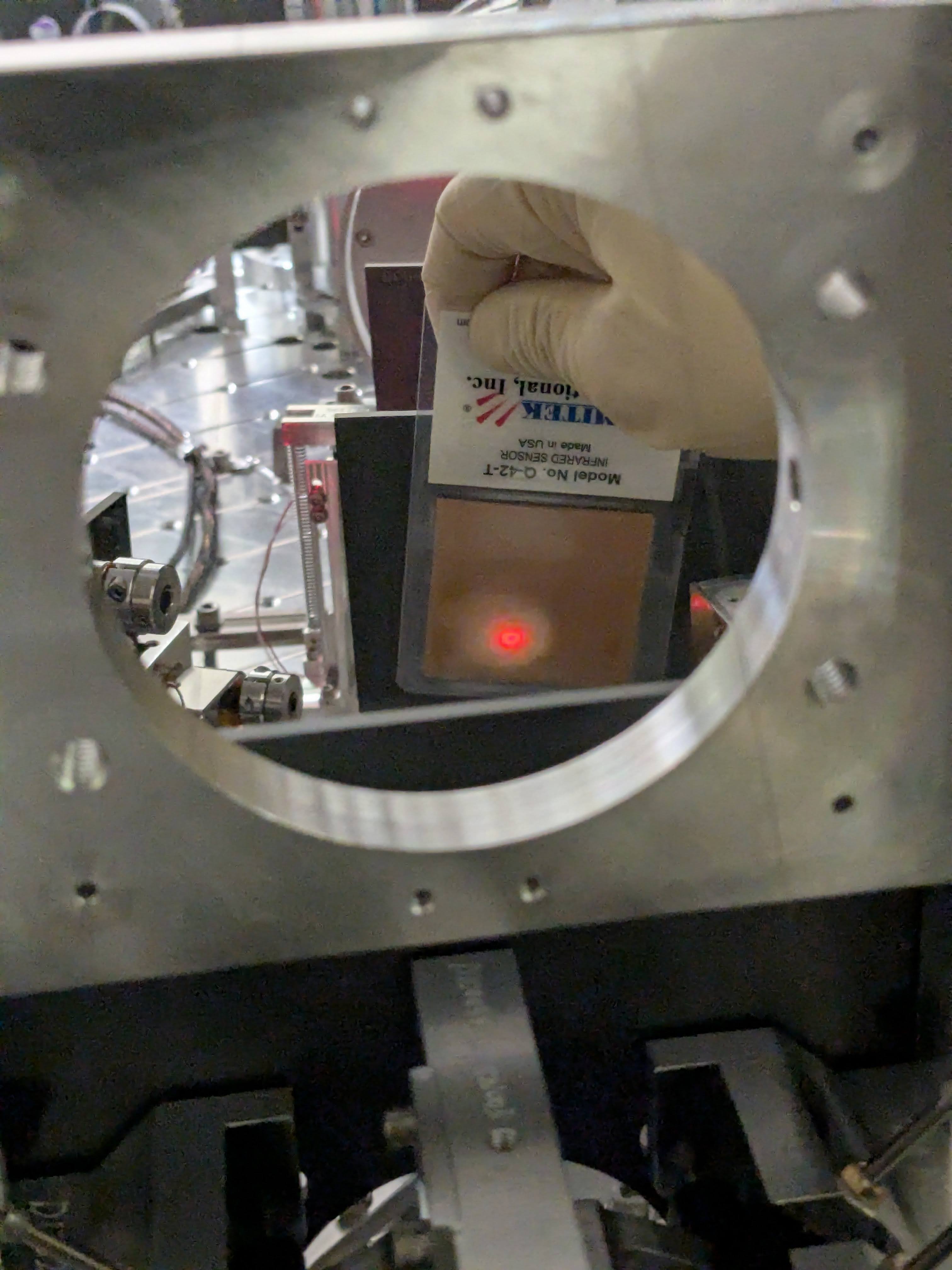
As of now, the measured beam position in front of MC mirrors are as follows this. For measurement points, see mc_beampos_measurement_cartoon.jpg. The height is pretty good for all. MC3 is great horizontally too. Beam spot on MC2 and MC1 are both shifted in -Y direction.  MC2 by 3.6+-1mm, MC1 by a couple +-1mm.

  Height from ISI measured [nominal] Horizontal shift in Y direction from the nominal beam position
MC1 154.3 +- 1.3 [155.5] -1.9 +- 1
MC2 167 [166.7] -3.6 +- 1
MC3 154 +- 0.5 [155.5] +0.3 +- 1

Horizontal positions were determined by covering half of the beam with a vertical hard edge (ruler etc.) and then measuring the position of the edge relative to the neighborhood screw holes using a small ruler, and then using the drawings (D0901088, D901089, D0901099) as well as other IO documents (e.g. T0900486) to figure out the nominal beam location. As an example of tedious work done, see ham2mc1.png. Due to the way it was done, we cannot determine the horizontal position of the beam much better than maybe 1/2 of the beam radius. I just put +-1mm error for all measurements. Height numbers were measured off of a ruler, the error bar (if any) is the difference between Rahul's reading and mine divided by two.

What if we move MC2 or MC3 beam spots (or both) to unclip IM4 baffle (HA12)

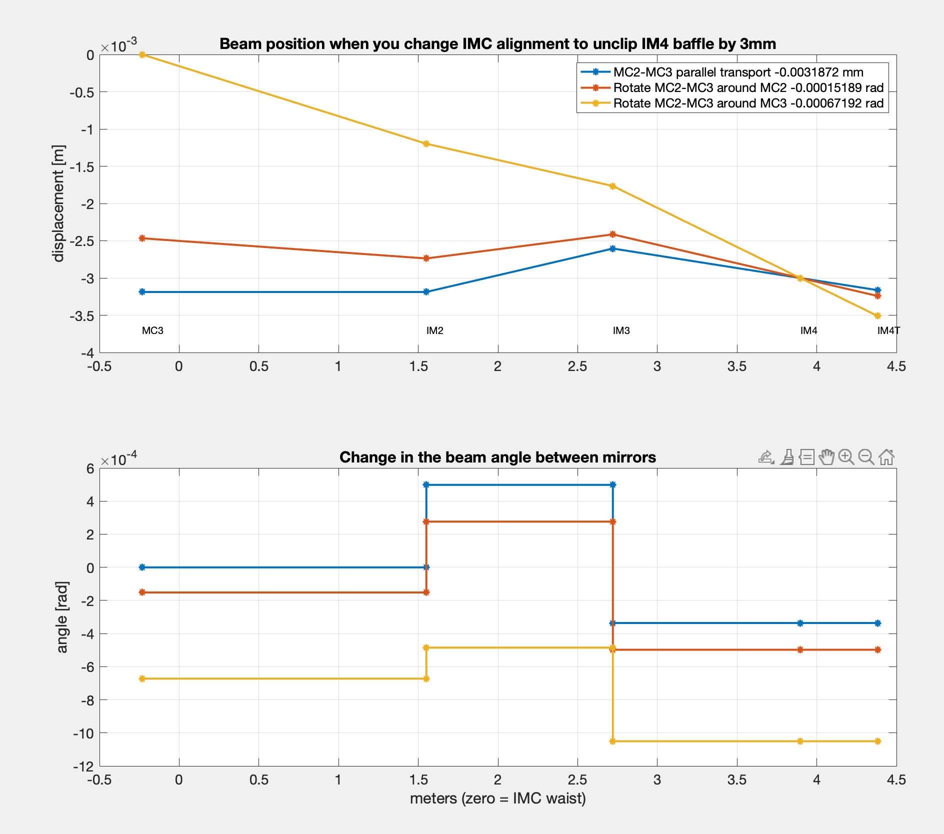
To get more sense of magnitude of IMC motion relative to the beam motion on IM4, I calculated how much the IMC alignment should be changed to move the beam on IM4 by 3mm in -Y direction (comfortably far from clipping but not enough to center) without moving IMs.

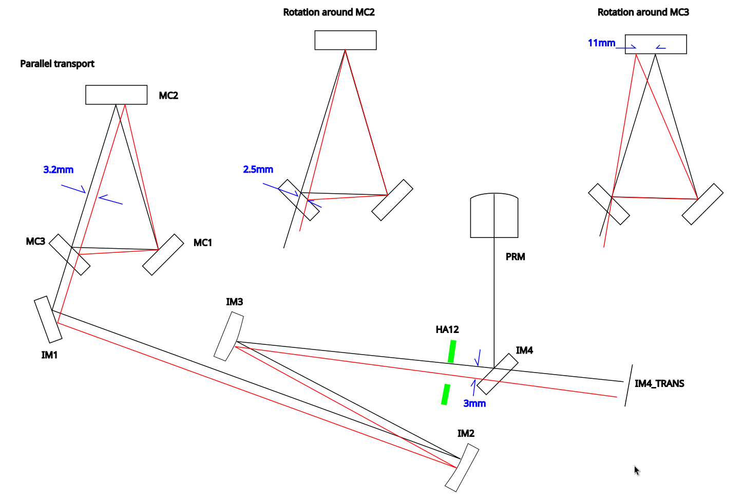
There are many linear combinations of the MC3 spot position and the angle of the beam coming through MC3 that will move the beam on IM4 by 3mm, so I just chose "parallel transport of MC2-MC3 line" (i.e. no angle change of the angle of the beam coming out of MC3), "rotate MC2-MC3 line around MC3" (i.e. no beam displacement on MC3) and something in-between ("rotate around MC2").

See cartoon_IMC_alignment_to_unclip.png (not to scale but the sign of displacement/rotation is correct along the entire path) and IMC_to_unclip_HA12.png (actual calculation). IMC is not the only thing that moves, we can also move IM2, but anyway. In the "parallel transport" case the beam will be move further away from the center of MC2 (remember it was already 3.6+-1mm in -Y direction to start with so the end result will be 6.8+-1mm in -Y direction). OTOH in the "rotation around MC3" case, the beam on MC2 will move by 11mm in +Y direction so the end result will be 11-3.6+-1=7.4+-1mm in +Y direction.

In all cases the beam will likely still hit the IM4_TRANS because the QPD (Excelitas C30845) has a huge 8mm active diameter, but it will likely be completely in one quadrant. So all of these will be bad solution if we believe that the IM4_TRANS position should be close enough.

Note that the "rotation around MC3" case will result in about 1mrad beam angle change on IM4. This needs to be absorbed by IM4 rotation by about 500urad to send the beam to PR2. 

It's also worth noting that IM4-PRM HR distance is almost the same as IM4-IM4_TRANS distance.

What if we fix the beam on IM4_TRANS?

Instead of IMC alignment, now let's think about the beam positions from the end point (IM4_TRANS).

Again, assume that we want to keep the IM4 TRANS beam position. We tried two different IMC alignment, and the beam was clipped on IM4 baffle (HA12) after bringing the beam back to the target IM4 TRANS position.

Moving the beam position on HA12 by 3mm in -X direction without changing the IM4_TRANS position means that we shift the beam position on IM3 by about 8mm. IM3-IM4 path beam angle changes by 4.8mrad counter-clockwise. This is an absolutely huge change. 

PRM should be moved by 2.4mrad, and 8mm on IM3 is already the radius of IFI output baffle (HA6)  so we'll be worrying about clipping there. There seems to be no solution where the beam is far enough from the IM4 baffle (HA12) edge AND the beam is on the same position on IM4_TRANS as in vacuum. 

As far as we assume that IM4_TRANS is trustworthy, it's very likely that the beam was clipping or at least very close to clipping on HA12 in O4.

However, if IM4_TRANS path moved after HAM2 was opened (i.e. somebody bumped something), IM4_TRANS position as of now doesn't mean anything. We have to at least grab and wiggle the steering mirror as well as the QPD for that path to make sure that nothing is loose. (I already did that test for MC2 TRANS, and they didn't move.)

Images attached to this report
Comments related to this report
keita.kawabe@LIGO.ORG - 17:42, Thursday 21 May 2026 (90305)

Attached are an example of beam position measurements (in this case MC1).

Images attached to this comment
keita.kawabe@LIGO.ORG - 13:41, Friday 22 May 2026 (90321)

IM4_TRANS path optics (pickoff for the ISS path, pico for IM4_TRANS centering) as well as the IM4_TRANS QPD itself seemed to be firmly attached to the pole and the ISI table. I grabbed them using my hand and wiggled and they didn't move at all.

keita.kawabe@LIGO.ORG - 17:23, Friday 22 May 2026 (90327)

PIT angle of the beam from IM4 to PRM AR to PR2

The beam is level between IM1 and IM4 and then goes up toward PRM, but I cannot easily find how much. So here's a quick note.

  MC3 IM1 IM4 PRM AR PRM
Height [mm] 155.5 155.5- 155.3   158.8
Angle [rad] of the exiting beam relative to the horizontal plane   level 8.5m 628u 628u

Nominal height of MC1 and MC3 center is 155.5mm (D09010088, D0901089). IM1 beam height should be pretty close though MC2-MC3 line is not level.

The beam from PRM HR to PRM is tilted up by 0.035966 deg = 628urad (I'm using the PIT angle of PRM itself in  D0901920 rather than reading the coordinates of PRM and PR2).

PRM has 1 degree vertical wedge (D0901172), the bottom being widest, so the beam is tilted up from IM4 to PRM AR by ~(n-1)*1deg = 0.4497 deg relative to the PRM-PR2 line, n being the refractive index of fused silica for 1064nm (1.4496).

The beam from IM4 to PRM AR is therefore tilted up by (0.4497+0.035996) = 0.4857 deg = 8.5 mrad relative to the horizontal plane.

PRM center height is 158.8mm nominal (D0901090) and the distance from PRM AR to IM4 is 415.9mm (T0900486), so the beam height at IM4 should 158.8-415.9*8.5mrad = 155.3mm, which is good enough of an agreement with MC3 height.

FYI I measured the IM4 baffle height this morning and it was (206+104)/2 =155mm, so the baffle height should be correct. (The beam is low on that baffle though YAW is the worse problem than PIT.)

keita.kawabe@LIGO.ORG - 11:25, Thursday 28 May 2026 (90336)

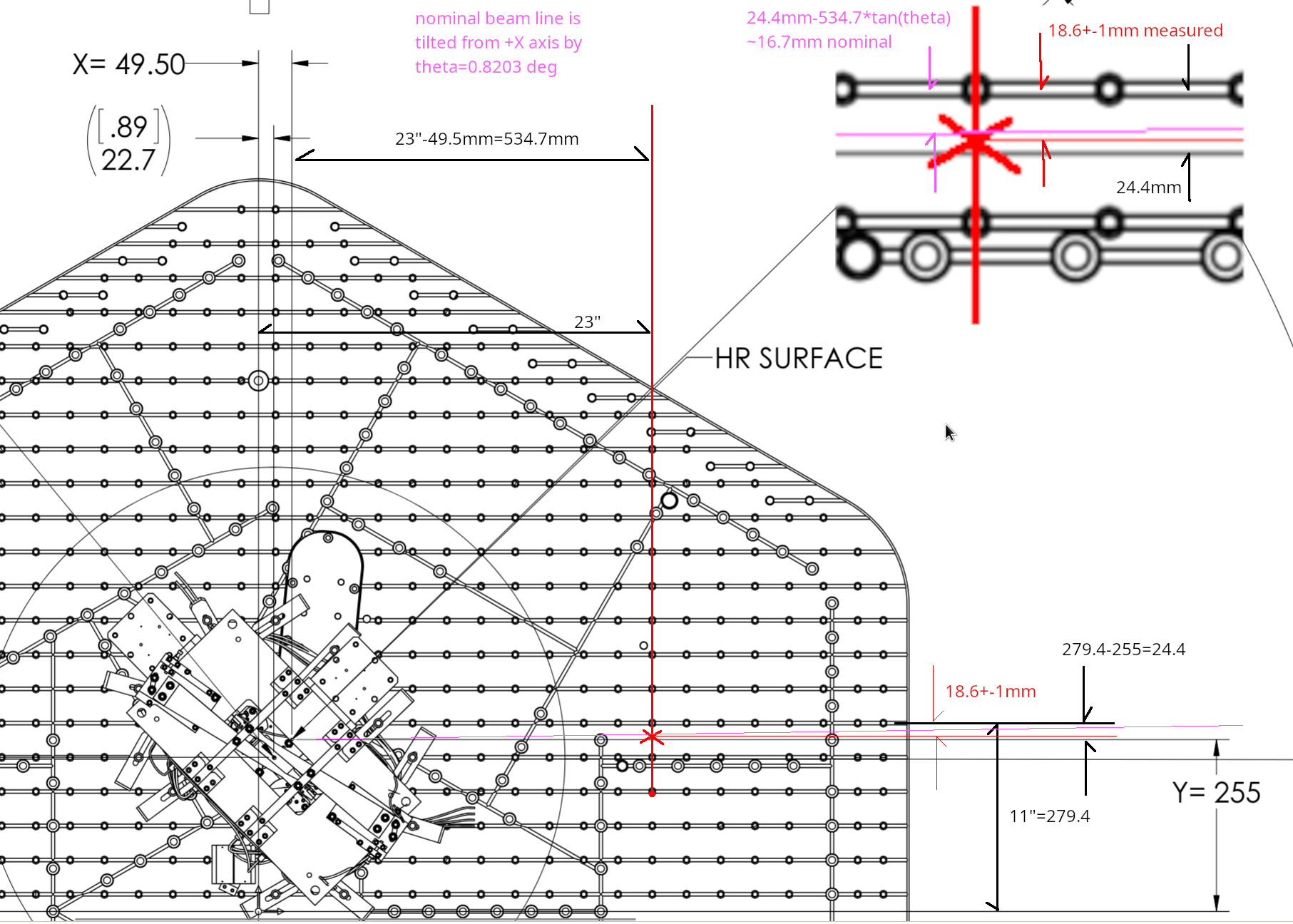
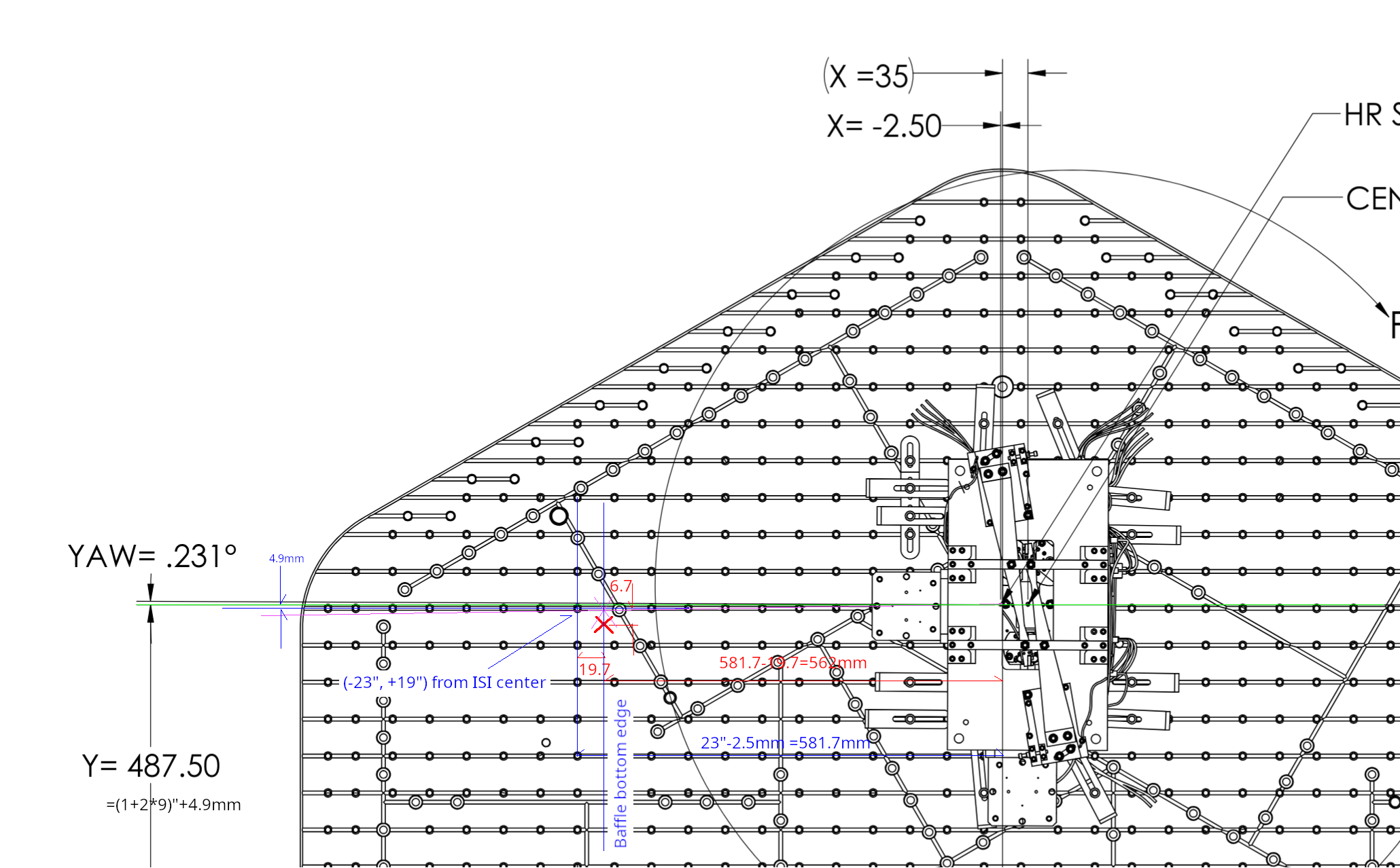
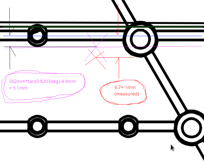
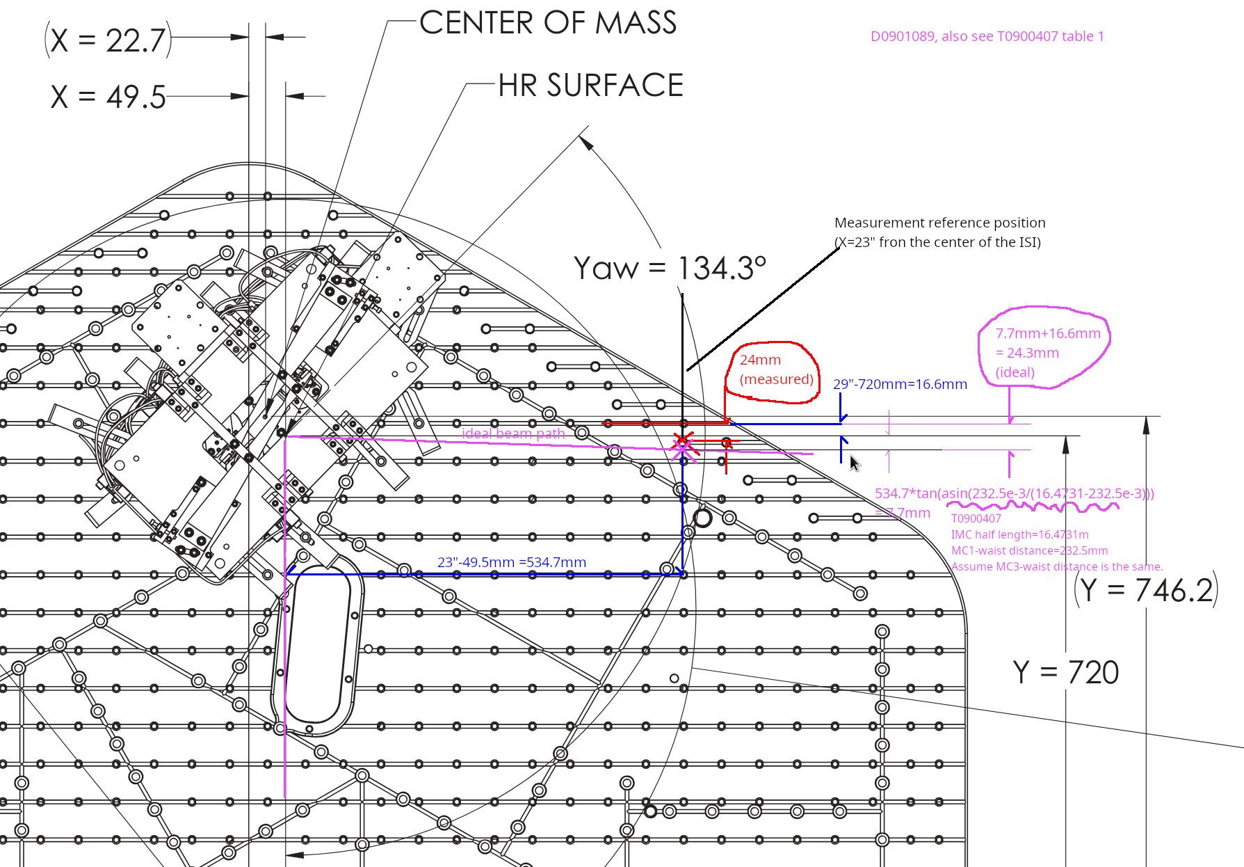
This is the beam position measurements for MC2 and MC3.

Note: In D0901099-V2 on page 9, it looks as if MC2 HR surface is supposed to be rotated by 0.231 degrees clockwise seen from the top.

I don't think that makes sense unless the ISI table itself is supposed to be rotated 0.231 degrees counter-clockwise because the IMC is an isosceles triangle, MC1-MC3 line is parallel to Y axis and MC2 Y coordinate is the mean of MC1 and MC3 Y coordinate according to the global coordinates of MC1, MC2 and MC3 (E1100494-V4, E1100494-V6).

I assume that the ISI tables aren't nominally rotated around local Z axis.

  Global X Global Y Global Z
MC1

-20,072.0

255.0

-97.3
MC2 -3833.1 487.5 -87.3
MC3

-20,072.0

720.0

-97.3


Images attached to this comment
Displaying reports 561-580 of 88336.Go to page Start 25 26 27 28 29 30 31 32 33 End