Displaying reports 601-620 of 88344.Go to page Start 27 28 29 30 31 32 33 34 35 End
Reports until 09:35, Tuesday 26 May 2026
H1 CDS (SEI)
filiberto.clara@LIGO.ORG - posted 09:35, Tuesday 26 May 2026 (90337)
Corner Station HEPI

WP 13259
ECR E2200043

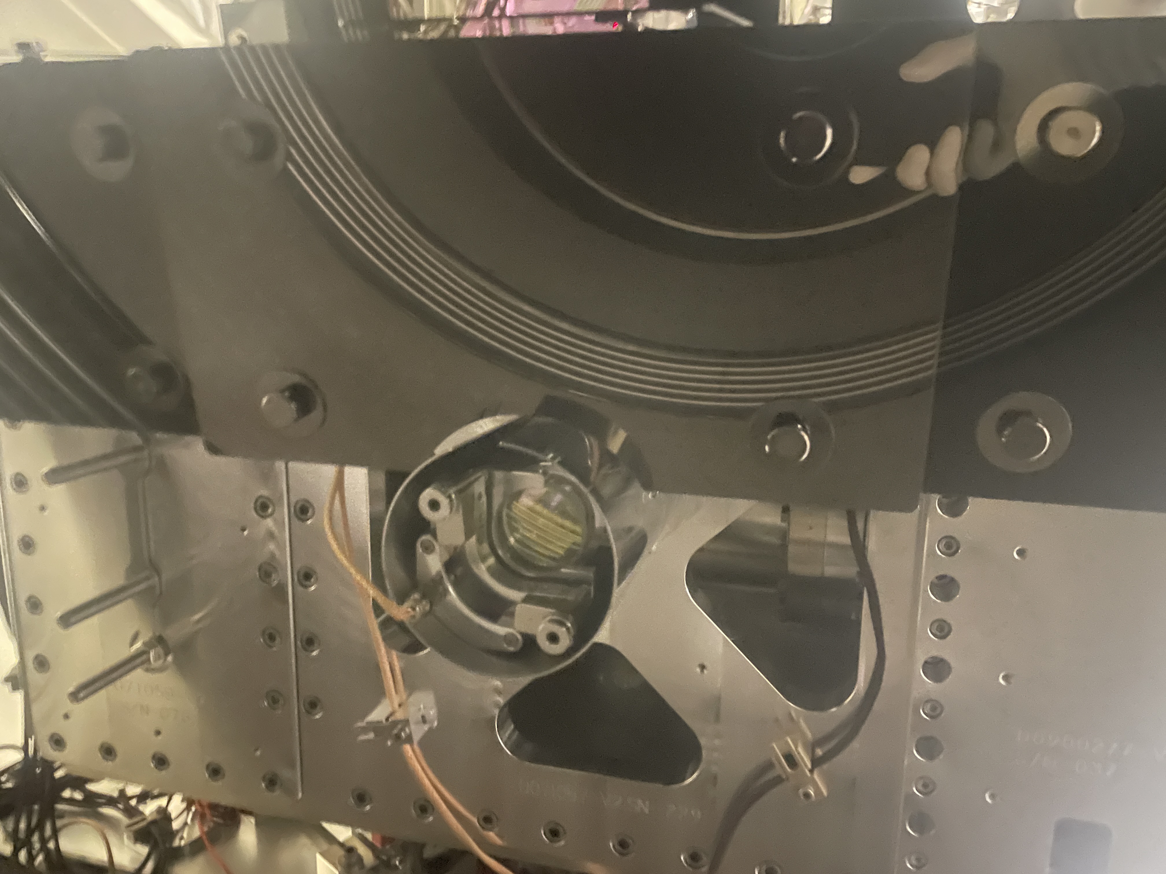
The CS HEPI system is planned to be upgraded to a Beckhoff PLC system. Modifications to the motor control panels to readout the VRD readback signal completed. Cabling and panel connections cleaned up. Part of ECR E2200043.

Prior to starting work:

  1. All pump stations were locally powered off via the front panel OFF button
  2. Breakers to pump stations powered off
  3. An anti-static floor mat and a grounding wrist strap used when working on the control panels
H1 PEM (SPI)
thomas.shaffer@LIGO.ORG - posted 08:08, Tuesday 26 May 2026 - last comment - 10:38, Friday 05 June 2026(90335)
HAM2 Beard Baffle for SPI Placed and B&K'd on Friday

Mitchell and I placed the new central beard baffle with a cutout for SPI on HAM2. It went on without issue after Mitch reminded me how to adjust the panels.

I then attached the accelerometer to the L bracket and tried hammering in various places. There wasn't much real estate, so I'm not sure how this will turn out. Data still needs to be analyzed, and I'll post pictures of hit locations then as well.

Images attached to this report
Comments related to this report
mitchell.robinson@LIGO.ORG - 12:41, Tuesday 26 May 2026 (90342)

For clarity, this is a D1700265-V4 Ham ISI Table Baffle "Below Table"

No SN's for each of the 3 asseblies were tracked during initial install. Comments and the new SPI type 3 baffle panel as well as the type 2 that was removed will be added to D0901083 WHAM2 top level. Originally, pre SPI, the configuration would have been 2x type 01 and 1x type 02. The type 02 changes to a type 03 for the SPI configuration.

Work Permit 13238:

Change out +X-side, center, HAM2 ISI table baffle from D1700265-v4 Type 2 to D1700265-v4 Type 3 in support of SPI HAM2 ISIJ assembly install (WP:13237) per DCN E2600005 that converts HAM2-H1, XYZ Local for HAM ISI BAFFLE ASSY D1700335-v1 to -v2.

jeffrey.kissel@LIGO.ORG - 10:38, Friday 05 June 2026 (90502)
Serial numbers for these baffle assemblies can be found in LHO:90501.
H1 General
oli.patane@LIGO.ORG - posted 07:46, Tuesday 26 May 2026 (90334)
Ops DAY Shift Start

TITLE: 05/26 Day Shift: 1430-2330 UTC (0730-1630 PST), all times posted in UTC
STATE of H1: Planned Engineering
OUTGOING OPERATOR: None
CURRENT ENVIRONMENT:
    SEI_ENV state: MAINTENANCE
    Wind: 3mph Gusts, 1mph 3min avg
    Primary useism: 0.03 μm/s
    Secondary useism: 0.57 μm/s 
QUICK SUMMARY:

Tuesday Maintenance day today!

H1 CDS
erik.vonreis@LIGO.ORG - posted 07:29, Tuesday 26 May 2026 (90333)
workstations updated

Work stations updated and rebooted.  This was an OS packages update. Conda packages were not updated.

H1 SPI
jeffrey.kissel@LIGO.ORG - posted 22:12, Monday 25 May 2026 (90332)
2026-05-22 SPI Pathfinder Update: Two Steps Forward, One Step Back
J. Kissel, [S. Koehlenbeck remotely supporting]
(Belated aLOG)

Working with Sina over zoom, we tackled several of the issues reported in the last update (LHO:90313). In the discussion below, I use the same numbers as the issue list from the last update; they were prioritized, so I tackled things and had successes (and one failure) in that order.

The good news first:
    (1) FORWARD The issues with the low (then 35%) efficiency on the REF IFO were merely that I hadn't spent enough time walking the beam around. In the end, without adjusting the REF beam's input alignment at all, I was able to lock down the alignment set screws M_B2 and M_M3 which steer the MEAS beam into the IFO, while having IFO REF A reporting 99.0% efficiency, and IFO REF B reporting 97.2% efficiency. Very very excellent. 
        Final answer 
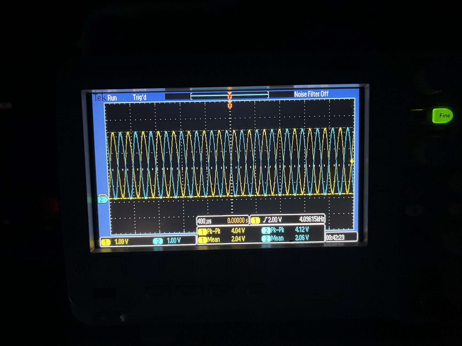
             (both traces at 1.0 [V/DIV])
             (only measurement of positive leg, not fully differential)
             (room lights and clean room fan off)
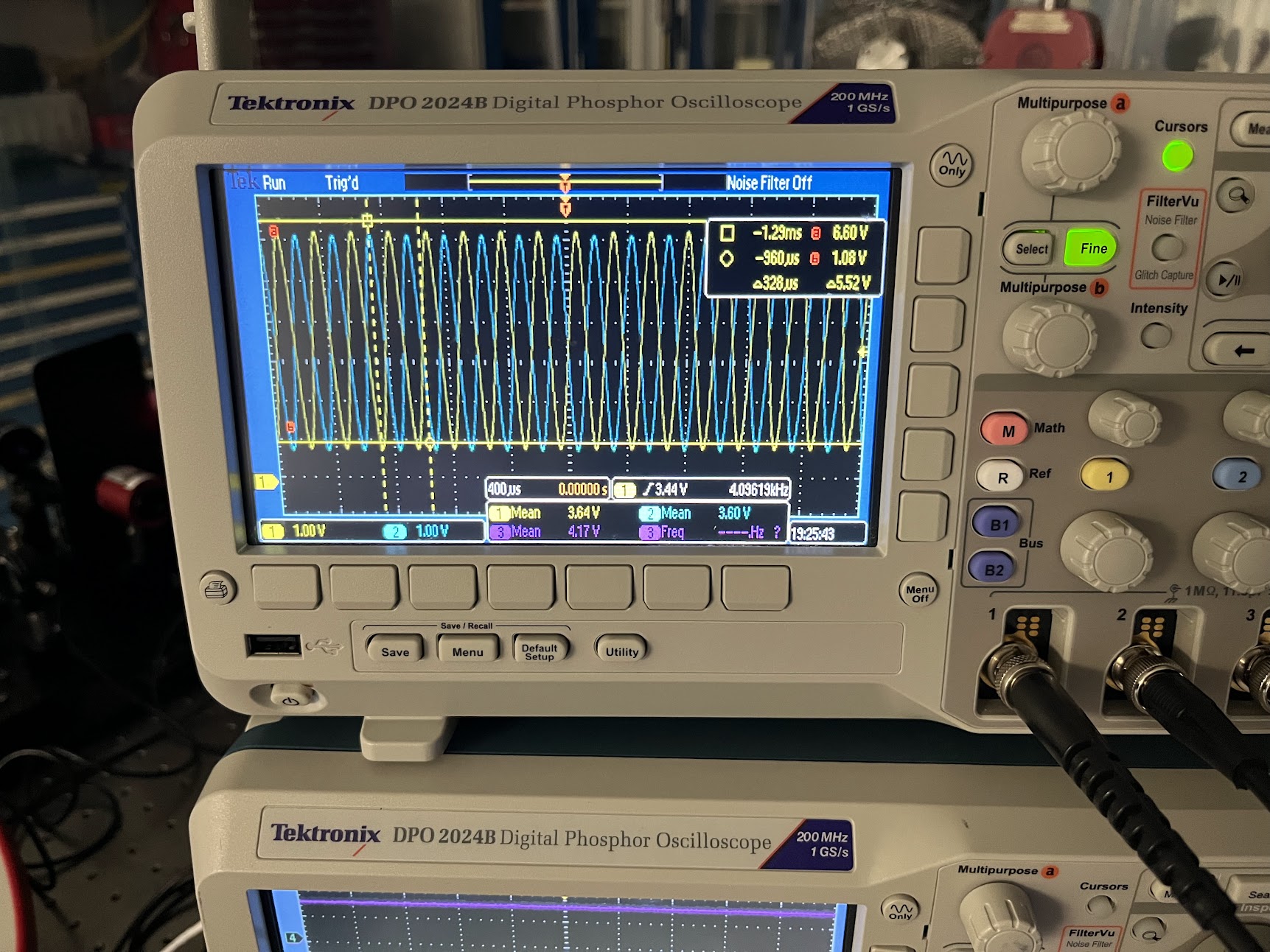
	     o-scope measured PEAK to PEAK (i.e. amplitude AMP) REF A and B = 4.04 and 4.12 V
	     o-scope measured MEAN: REF A/B = 2.04 and 2.12 V
	     Efficiency AMP / (2*MEAN): 
                 REF A = (4.04 / 4.08) = 0.99
                 REF B = (4.12 / 4.24) = 0.972
    Attachment 1 shows a picture of the o-scope with evidence of these numbers.
    Let's hope this sticks -- it gives us a LOT of confidence about what these IFOs (and laser delivery system) are capable of once alignment has been optimized and and other issues have been mitigated. I also still see no evidence that the REF IFO efficiency "breaths" on the ~minutes time scale like I've seen with the MEAS IFO.

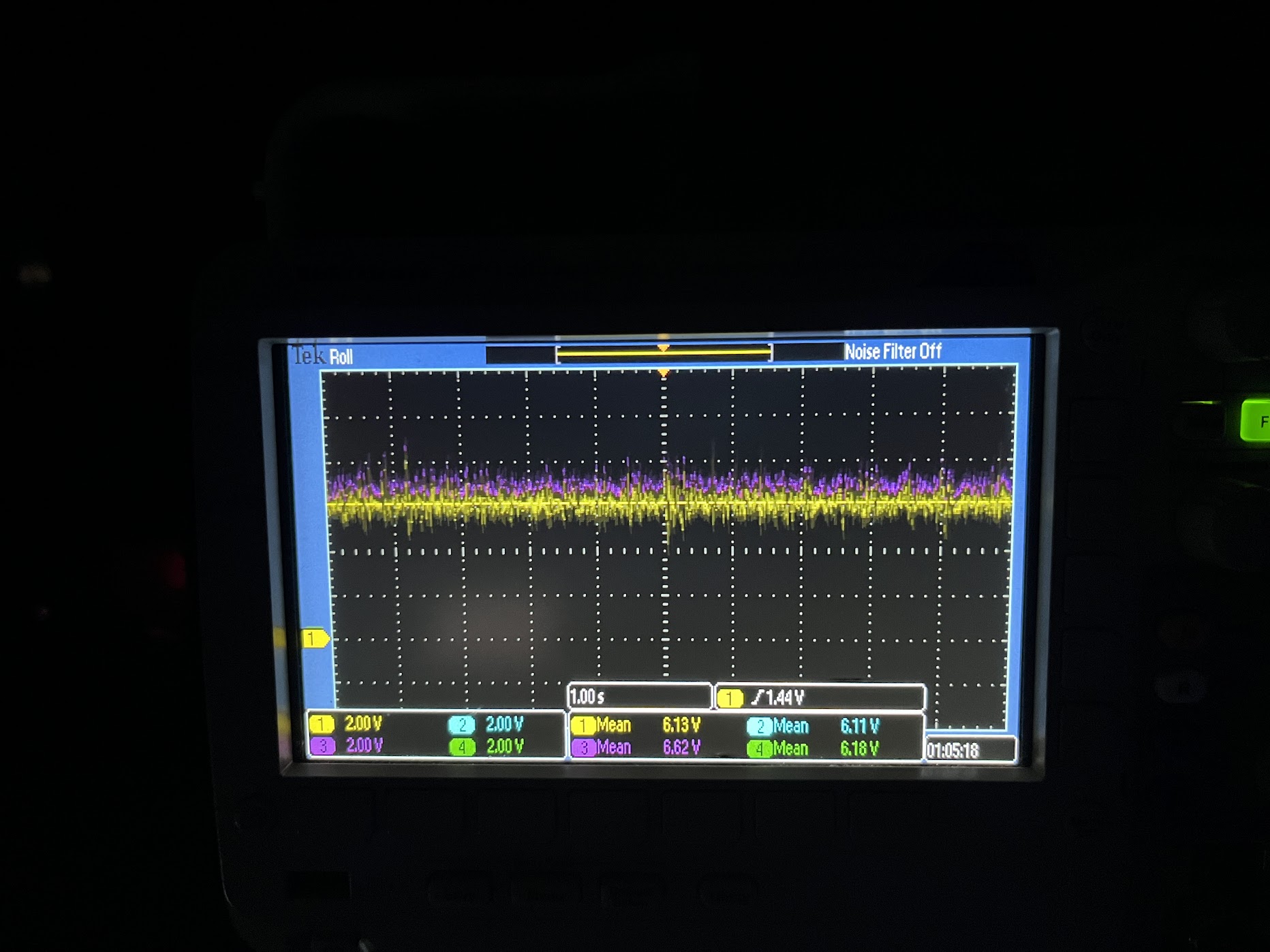
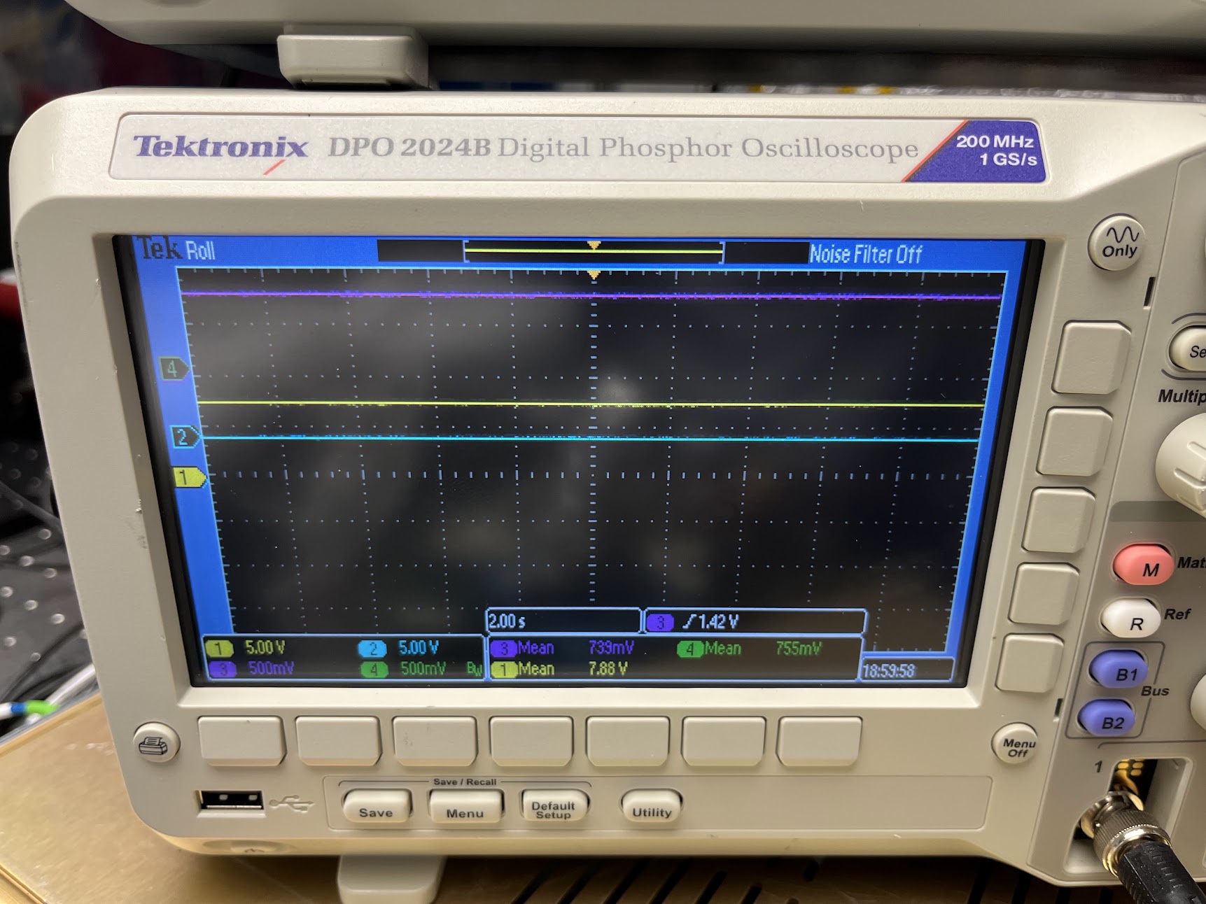
    (2) FORWARD Speaking of the MEAS IFO, along its MEAS beam path I addressed the issue with QPD B's reflection being wildly off in yaw. I was able to adjust the physical yaw position of OL_QPD_B with the slop in the enclosure's bolt holes such that the QPD reflection landed comfortably on the D_OL_QPD_B dump as it was originally; QTY 2x of the 1.0 x 0.75 [inch] plates (D1800140 Type 07). Said differently for clarity: I swapped out the QTY 2x of the 1.68 x 1.68 [inch] plates I cobbled together that was causing potential clipping issues (LHO:90315. I then centered the beam on the QPD using M_M1 as the steering mirror and and the QPD readout voltages as the metric for "centered." 
        Final answer
            (all traces at 2.0 [V/DIV])
            (only measurement of positive leg)
            (room lights and clean room fan off)
                                                         -X
            CH1  |  CH2          6.13 V  | 6.11 V         ^
            -----------  =       ----------------         |
            CH4  |  CH3          6.18 V  | 6.62 V         .---> +Z

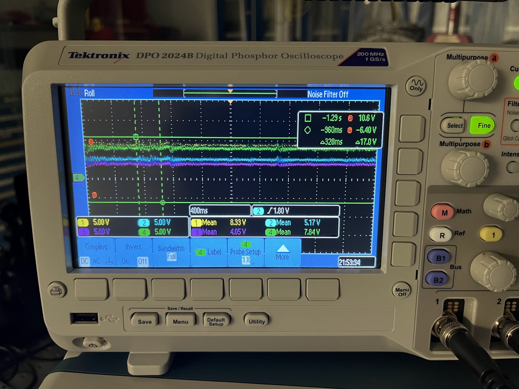
     Attachment 2 shows a picture of the o-scope with evidence of these numbers.
        I was not able to find a position on the QPD where every quadrant was balanced (and thus presumably the beam was truly centered) with my hand-adjustments of the picomotor knobs. But -- I was able to consistently get positions where 3 quadrants that were equal to within 50 [mV]. This is not worth fighting in the lab, since then return beam will be entirely different, and we can and will need to use picomotors with digital actuation.

Now the bad news:
    (3) BACK While then "finishing up" the on-board alignment, I found I was unable to find *any* beam steering with M_B4 and M_M2 that could achieve any higher efficiency than 50%. And this is the IFO that had 72% efficiency "easily" on 2026-05-19 (LHO:90289).

    Because I spent the rest of the day in the lab focused on finding an alignment that worked, I didn't get the chance to investigate any of the breathing. So we stopped for the day, worried that I was optimizing the alignment during on of the "breathing" episodes. So -- no progress on the problem what we really wanted root out AND we made things worse. Remember, we need >75% efficiency -- especially on this IFO, our primary measurement. So, it's not like we're hand-trimming the tips of the grass we've already mowed.

    ACTIONS/IDEAS:
        - The REF IFO beam is clearly great, given the awesome efficiency of the REF IFO. So it's gotta be something going on with the MEAS path to the MEAS IFO. 
            . Check the MEAS path beam positions on M_M1, M_B4, M_M2, and M_B3, and make sure we're not close to the edge of one or more optic.
            . Check -- quantitatively with a power meter, not just via card -- that we're not clipping thru the periscope 45 deg adapter mounts.
            . Inspect the optical surfaces of the mirrors, make sure we haven't incurred any damage or schmutz.
        - We found that the picomotor adjustment screw's SS ball bearing tip for the pitch / vertical actuator of M_B4 looks suspiciously smaller than other actuators on M_M1 and M_M2. The suspicion being that the too-small ball is inhibiting the kinematic adjustment of pitch, making reproducability in alignment a challenge. Maybe when I was assembling them (LHO:87497), a too-small SS ball got in the mix. The drawing for the 830X-UHV Picomotor (E1000197) says this should be a 4.8 [mm] = 0.188976 [inch] diameter ball bearing (rounded up to 0.19 [inch] in the drawing; or vice versa, 0.19 [in] was rounded down from 4.826 [mm]). Could very well be that I somehow found a 0.1875 = 3/16 [inch] SS ball bearing. So, I'll do some spares-kit diving to see if I can swap out this ball bearing.
        - If worse gets worse, we're also going to pull the IFO MEAS PD, and set up a beam profiler. If one can't find good efficiency with alignment alone, then the suspicion becomes beam quality. If we find the MEAS beam into the MEAS IFO is of poor quality, I'm hoping that some of the "would definitely distort the beam quality" ideas from above will solve the issue. But if we don't see anything, we'll at least have another metric as to why.

In other, neutral news:
    (1) While trying to rule out other issues with the REF IFO, before I found success in alignment, I checked every single mirror / beam splitter on the board and confirmed that it had its reflective surface facing the right direction. I also confirmed that the alignment of the M_F1 beam, transmitted thru M_B1 and M_B2 landed well-aligned on to the FBT_PWRIN_MEAS PD, with an iris in hole 88.

    (4) I checked how secure the fiber collimators' tiny-tiny set screws were on the ferrule of their incoming optical fiber. This was in hope of finding something obvious regarding p-pol transmission dependence on physical position of optical fiber. It's a completely indescribably feeling of how tight they need to be, but "you can tell when its too tight," and too tight *sometimes* results in the symptoms I was seeing regarding changes of physical positioning of the fiber impacting the output polarization (due to the set screw spoiling the polarization maintaining properties of the fiber, causing some yucky birefringence). It can also be too loose, too, and that just results in the optical fiber ferrule being able to move within the collimator, changing beam alignment out of the collimator.
    
    The M_F1 collimator's ferrule set screw felt "just right." It was secure, and it didn't take any finger strength with the tiny 1.2 [mm] flat-head driver to loosen or re-secure a few times with "just barely tool tight, using no actual pressure."
  
    The R_F1 collimator's ferrule set screw did feel "too tight." And it this REF fiber's position that I noticed had the most affect on the p-pol power transmitted when I re-noticed the issue. After re-securing the fiber "just right," I no longer saw obvious fiber position dependence of p-pol transmitted power.

    I call this "neutral" news because we're going to have to disconnect and reconnect the optical fibers again to install these feedthrus in the HAM3 chamber. So, "lesson learned" but we're gunna need to check for such dependence again once the transceiver is in the chamber.

    (5) Have not yet cracked open the FBR_PWRIN_REF PD to find the source of the (we suspect) alignment issue.

    (6) Phase drift of MEAS IFO w.r.t. REF IFO. Remember -- suspected non-issue, suspect its a feature of air-currents. So I didn't follow this at all. But will do the "wave your hand above the breadboard" check again once I get the efficiency of the MEAS IFO back up.

    (7) Sensitivity of the IFOs to flicking of either MEAS or REF fiber. Remember -- non-issue -- this is why we have the REF IFO. Anything that distorts the phase in both the REF and MEAS IFO simultaneously is a non-issue, since we're taking the difference.
Images attached to this report
H1 SUS
betsy.weaver@LIGO.ORG - posted 08:48, Saturday 23 May 2026 (90329)
BBSS alignment status

(Betsy, RyanC, Jason)

Friday we spent more time understanding why the Yaw mechanics weren't effective on the BBSS. We found that a lot of the top mass OSEMs interfere a lot when adjustments are made so they were constantly hanging up and giving us false reading of our adjustments. So we ended up disassembling half the suspension, stripping all top BOSEMs and the middle stage 4-BOSEMs via the entire plate. Then we started to see actual Yawing with the adjustments. In the process however, we stripped one of the 10 blade locking screws. So more disassembly to remove the sheet plate and eventually the bolt.  We now have yaw in the ballpark, but need damping. Facepalm. So will resume reassembling the whole suspension and get damping going asap next week.  Will need to revisit the L measurement after we finish Y and P.


LHO VE (VE)
jordan.vanosky@LIGO.ORG - posted 17:34, Friday 22 May 2026 (90328)
Seal Replacement on GV7 Air Cylinder

Gerardo, Travis, Jordan, Sean (GNB tech)

Today a tech from GNB came to the site to perform maintenance on the air cylinder for GV7 after we were unable to hard close the valve, see alog 89625

We first soft closed GV8 (and replaced the faulty air regulator) as a safety during the GV7 work. We then marked and measured the positions of the reed switches on the cylinder threaded rod, then disconnected the top air line. Sean then disassembled, cleaned and replaced all of the seals in the cylinder head, and the top and bottom flanges. We did have to modify the wear band since the one in the repair kit was too long and the ends overlapped. We also installed the new cylinder, but the used one looked to be in good condition. We will keep that one as an emergency spare.

New grease was applied to all seals and the inside of the cylinder. In order to keep the seals and wear band contained while installing the cylinder, Sean used a plastic band around the cylinder which kept the seals in place as the cylinder passed over them, which was then removed once the cylinder made it past the top piston seal. The top flange was then installed, along with the reed switches and air line.

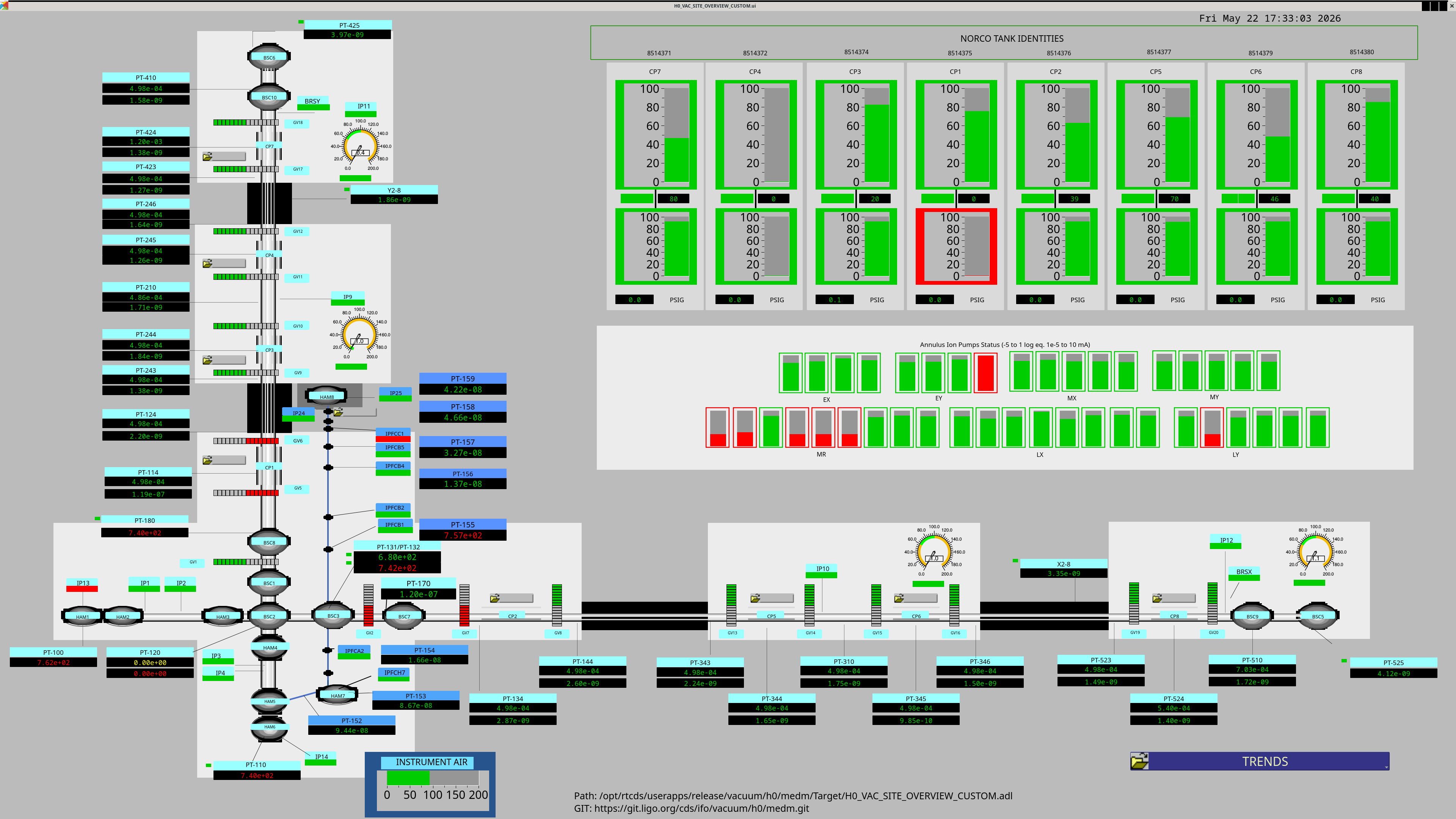
The valve was already soft closed during the repair, so to test we wanted to see if we could hard close. We noticed there was no longer any air leaking from the solenoid manifold, and we heard the audible "thunk" of the valve camming over (hard closed) at 40 psi, we confirmed the cds screen showed red for the valve status indicating the valve was hard closed. We then re-opened GV8.

No significant issues encountered, just a lot of cleaning of the old grease and seal grooves.

Full set of pictures/videos will be posted to the DCC and linked to this alog.

Closing WP 13256

Images attached to this report
LHO VE (VE)
gerardo.moreno@LIGO.ORG - posted 17:04, Friday 22 May 2026 (90318)
New Update On Purge Air Compressor Kobelco Unit

(Jordan V., Travis S., Richard M., Filiberto C., Dave B., Patrick T., Jonathan H., Brandon P.(RMC), Gerardo M.)

(Work done on 5/21/2026)
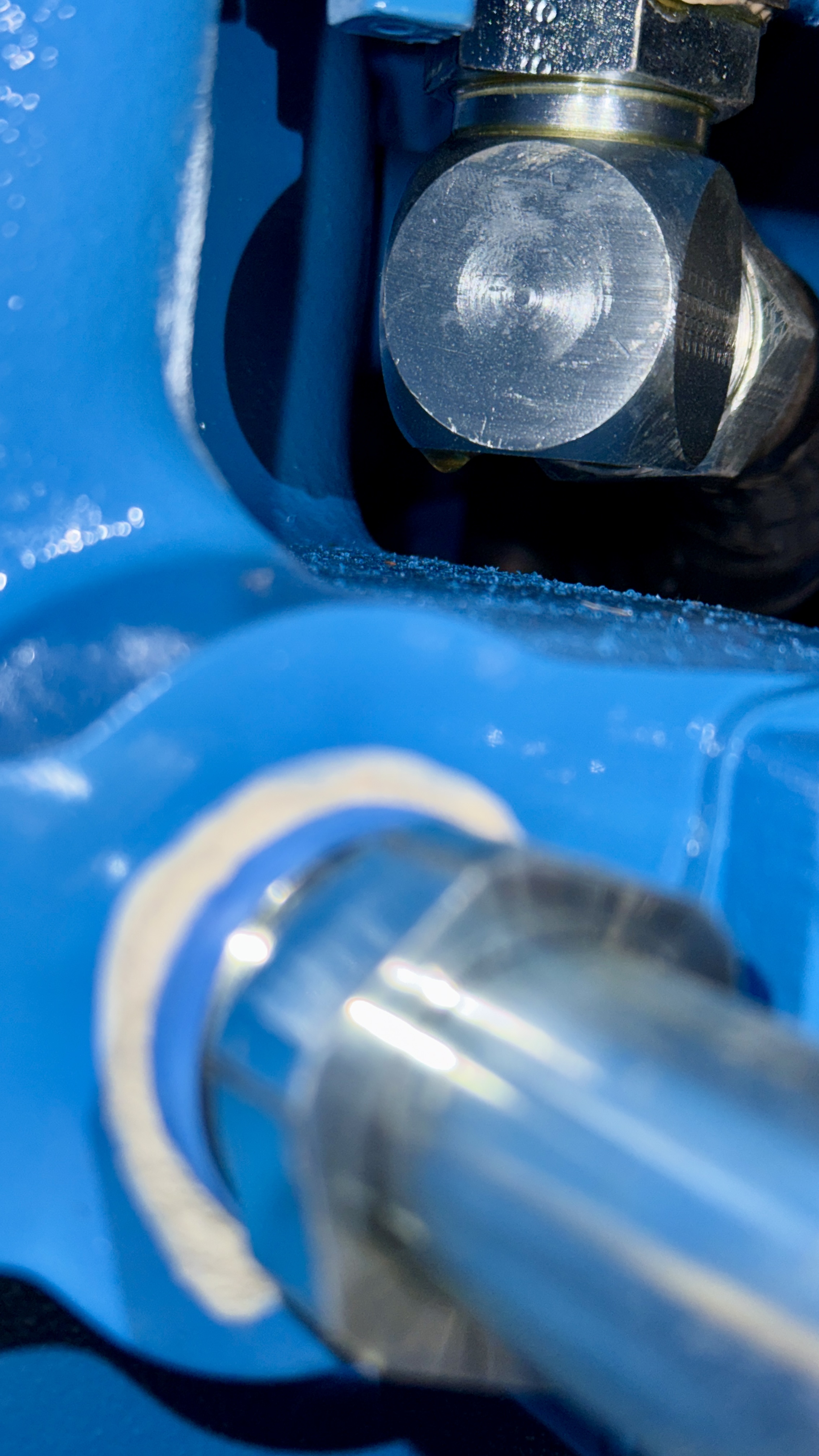
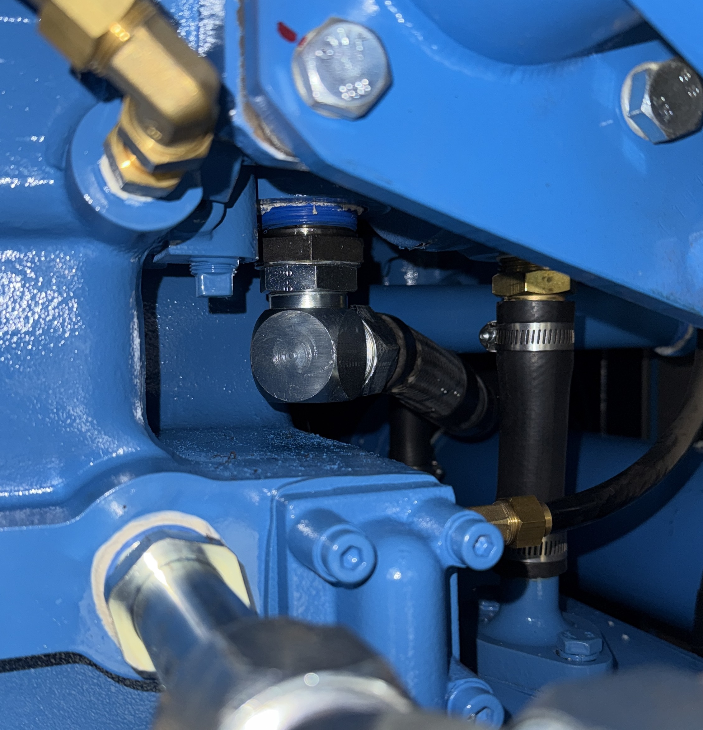
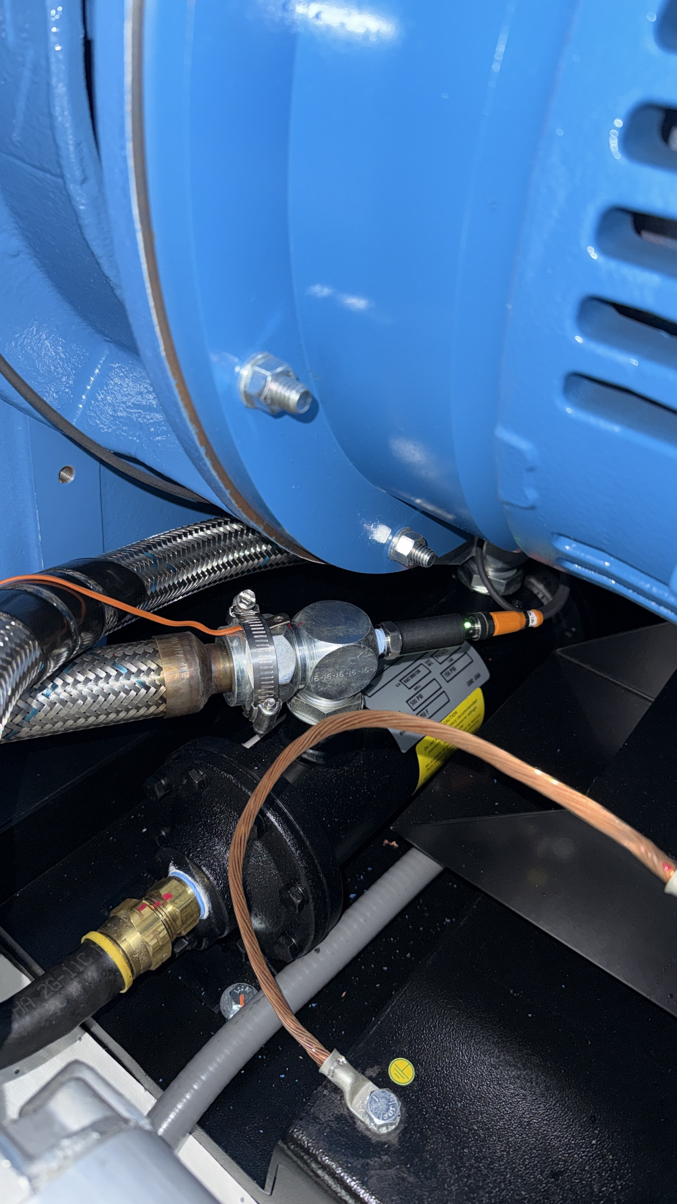
The new purge air compressor, Kobelco KN-0, developed a very small oil leak (again).  A few weeks ago oil started oozing out of some of the oil line connections, about 3 different spots.  See photos.  Technician Brandon Pimentel showed up Thursday morning, and not only did he found the above mentioned slow leaks, but he discovered that the oil pump was also leaking (again), the seal at the drive shaft is not sealing.  That was the diagnosis, see report below.
Brandon turned the compressor off, then proceeded to fix leaks.  The oil pump will get replace later, he has order a new pump and should be here in the next couple of weeks.  The compressor was turned back on, it started working without a problem, "BUT" the HMI (control panel) did not returned!  After several tries at restarting the unit, Brandon and Field Engineering called HMI dead, and it needs to be replaced.  The HMI unit should be here within a week.

Meanwhile we were flying blind, the compressor is doing its job and compressing air and working with its regular schedule, but due to the oil leak on the oil pump, we've decided to attach a thermocouple to the compressor to keep an eye on the oil temperature, same location as the oil temperature sensor the HMI unit uses, then thanks to many people we now have a CDS signal for the oil temperature, see Dave's entry.
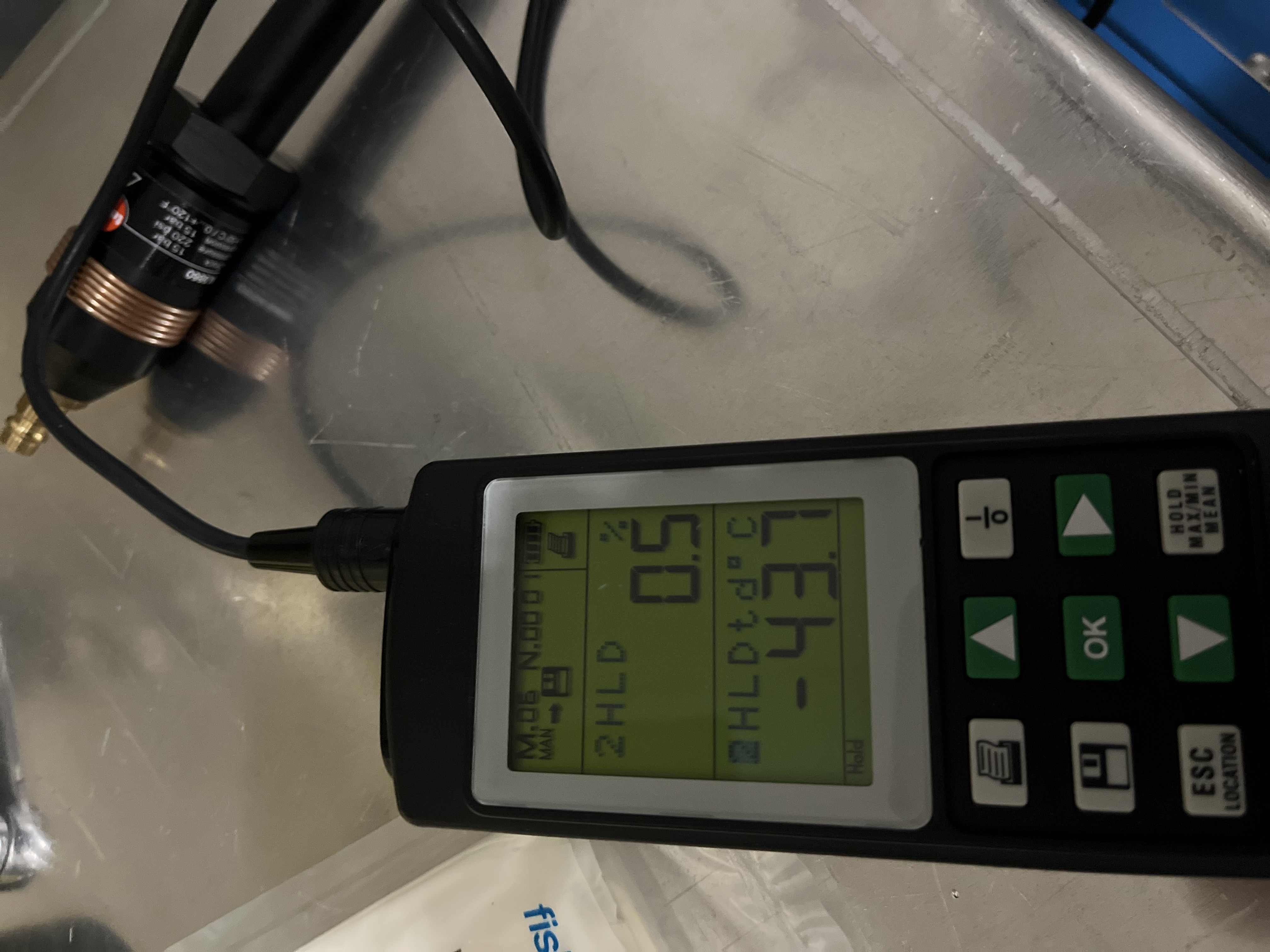
We let the unit run until the dew point at the drying towers was acceptable, then we released the purge air into the LVEA, we let the purge air run on the lines inside the LVEA for another hour, then we took a dew point measurement at the point of use, we read -43.7 oC.  Then we allowed the air into chamber and purged the chambers for 1 hour before allowing in-chamber work to resume.

Below is Brandon's report:                                

1/4IN OF OIL IN CABINET CUBICLE BELOW OIL PUMP. CLEANED UP OIL RESIDUE FROM ALL COMPONENTS.
REPLACED ORING ON OIL PUMP INLET LENS FITTING. TIGHTENED LENS FITTING BUSHINGS.
TEST RAN UNIT LOADED FOR 1 HOUR INSPECTED OIL PUMP HOUSING FOR EVIDENCE OF SHAFT LEAK AND COUPLING WEAR. FOUND 1/4 OF OIL INSIDE HOUSING AND RESIDUE ON SHAFT. NEED TO REPLACE OIL PUMP.
HMI IS BLACK-SCREENED AND UNRESPONSIVE. PER FIELD ENGINEERING, NEED TO REPLACE. UNIT IS OPERATIONAL.


Images attached to this report
H1 General
anthony.sanchez@LIGO.ORG - posted 16:34, Friday 22 May 2026 (90325)
Friday Ops shift report.

TITLE: 05/22 Day Shift: 1430-2330 UTC (0730-1630 PST), all times posted in UTC
STATE of H1: Planned Engineering
INCOMING OPERATOR: None
SHIFT SUMMARY:
Major work that was completed today: 
Gate Valve 7 is now repaired. 
L4Cs went insideHAM2 . 
Faroing yaw in the new beam splitter.
And Optics cleaning of CRS optics.
 

LOG:

Start Time System Name Location Lazer_Haz Task Time End
14:42 FAC Kim LVEA N Technical cleaning & Resupply 16:03
15:04 VAC Jordan LVEA N Gate Valve work 18:34
15:04 BBSS Betsy LVEA N Working on BBSS 16:01
15:25 IAS Jason LVEA N Pitch and Yaw BBSS Faro work 18:56
15:39 IAS Ryan C LVEA N Helping Jason 19:27
15:47 SYS TJ LVEA N BnK work inside HAM2 17:48
15:55 VAC Jordan & Travis LVEA N Closing Gate Valve 8! 17:14
16:16 SPI Mitchell LVEA N Taking parts out and setting up for SPI work 18:14
16:19 FAC Randy LVEA near Clean rooms N Clean room inspections. 17:08
16:22 VAC Gerardo LVEA n Walking around checking on various Vac equipment 17:14
17:00 SYS Jim LVEA HAM2 N helping TJ with BnK work 17:48
17:07 BBSS Betsy LVEA N Working on the BBSS 19:26
17:26 ISS Keita LVEA HAM2 N Going to HAM2 to do some In chamber work 18:34
19:24 SPI Jeff Optics lab yes Working on the SPI Optics 22:24
19:34 VAC Jordan & Contractor LVEA N Gate valve 7 work 23:01
19:40 SEI Shoshanna H2 PSL N Cleaning Optics 22:40
19:42 VAC Travis LVEA N GateValve work 22:15
19:58 IAS Ryan C LVEA west bae N BBSS Faroing YAW 21:30
20:00 BBSS Besty LVEA West Bae N More BBSS work 21:30
20:03 VAC Gerardo LVEA n Gate Valve 7 work 23:01
20:22 SEI Jim & Mitchel LVEA HAM2 N Installing L4Cs 22:52
20:52 pcal tony PcalLab y testing new laser 21:46
H1 SEI
jim.warner@LIGO.ORG - posted 16:11, Friday 22 May 2026 - last comment - 13:06, Saturday 23 May 2026(90324)
HAM2 L4C install

Mitch, Jim

We got a window this afternoon to try installing L4Cs in HAM2. We just did the horizontal L4Cs and cables, because those were the most difficult, but least in the way parts. The H3 L4C in particular was very difficult, I had to go in and work under the SPI ISIJ telescope, laying on my stomach in the beam tube, while trying not to kick the modecleaner baffle out of place. Also, the gap between bottom edge of St1 and the bottom of the nozzle to the modecleaner tube is just slightly narrower than my elbow, so I could fit my arm in there, but was never sure it would come back out easily. Anyway, the hard part is done, we will finish the verticals next week sometime. I also need to get back with Fil about running the in air cables to the feed thrus. We should have the in rack electronics next week some time as well, so I will try to get the adc wiring in the model set up before interface chassis arrives.

Images attached to this report
Comments related to this report
arnaud.pele@LIGO.ORG - 13:06, Saturday 23 May 2026 (90330)

For ADC assignment, see the green boxes on the redline posted to D1101576:
REDLINE_HAM23_Wiring_SPI_CRS_L4C_AA_ASSIGNMENT (P3)

If the Duotone channel is set on ADC0 CH31 as shown in this wiring diagram, we will have to skip the last db9 of the left AA shown on the picture above (or loose the Pod Pressure signal).

In summary, here is the proposal:
ADC0 CH24-25: L4C H1,V1 Signals
ADC0 CH26-27: L4C H1,V1 Diff Pressure/Pressure
ADC1 CH24-25 L4C H2,V2 Signals
ADC1 CH26-27: L4C H2,V2 Diff Pressure/Pressure
ADC1 CH28-29: L4C H3,V3 Signals
ADC1 CH30-31: L4C H3,V3 Diff Pressure/Pressure

H1 SUS
oli.patane@LIGO.ORG - posted 15:19, Friday 22 May 2026 - last comment - 09:58, Wednesday 27 May 2026(90323)
BBSS test stand transfer functions

On May 19th, 2026, we took our first set of transfer functions for the BBSS after swapping in the glass optic. They all came out looking good, albiet very noisy because the suspension wasn't covered.

Comparing them to the last measurement we did in the staging building, the peaks still all match up well. There is just a consistance difference in magnitude, but that is probably just due to the difference in electronics between the QUAD stand in the staging building and the BS electronics in the LVEA.

Data
/ligo/svncommon/SusSVN/sus/trunk/BBSS/H1/BS/SAGM1/Data/2026-05-19_2000_tfs/2026-05-19_2000_H1SUSBS_M1_WhiteNoise_{L,T,V,R,P,Y}_0p02to50Hz.xml
r13018
Results
/ligo/svncommon/SusSVN/sus/trunk/BBSS/H1/BS/SAGM1/Results/2026-05-19_2000_tfs/2026-05-19_2000_H1SUSBS_M1_ALL_TFs.pdf
r13018
/ligo/svncommon/SusSVN/sus/trunk/BBSS/Common/Results/allbbss_May2026_BBSS_teststand_vs_staging/allbbsss_May2026_BBSS_teststand_vs_staging_ALL_TFs.pdf
/ligo/svncommon/SusSVN/sus/trunk/BBSS/Common/Results/allbbss_May2026_BBSS_teststand_vs_staging/allbbsss_May2026_BBSS_teststand_vs_staging_ALL_ZOOMED_TFs.pdf
r13017

Images attached to this report
Non-image files attached to this report
Comments related to this report
oli.patane@LIGO.ORG - 09:58, Wednesday 27 May 2026 (90353)

These measurements were taken with BOSEMs. The extra factor of ~4 that these measurements are lower by as compared to the older staging building trace is due to electronics. The BSFM was moved from 18- to 28-bit DACs back in January, so I compensated for this change in the COILOUTF filter bank by adding a filter module with a gain of 1024. However, the BBSS measurements made in the staging building were using a 16-bit DAC, so when we moved the BBSS onto the BSFM system, there was a factor of four of drive missing from excitations, hence these measurements looking lower as compared to the measurements in the staging building. That was remedied after this.

H1 SUS
oli.patane@LIGO.ORG - posted 14:38, Friday 22 May 2026 (90319)
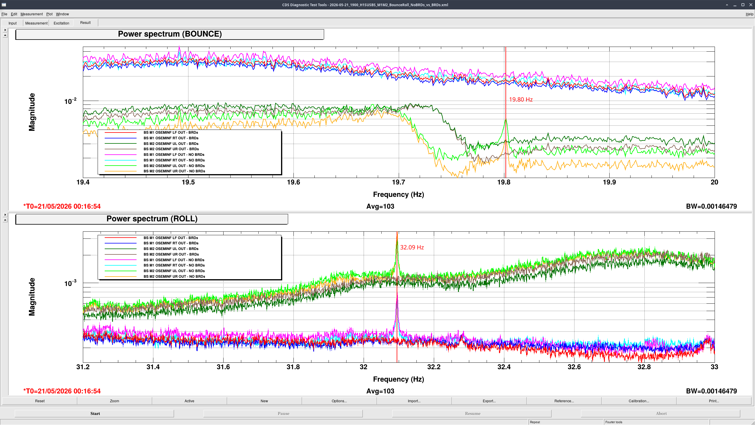
BBSS test stand BRD comparison results - Bounce and Roll

Comparison overnight spectra of the BBSS's M1 LF/RT and M2 UL/UR osems before vs after the installation of the BRDs is showing that the BRDs are correctly damping the Bounce and Roll modes and so don't need to be adjusted.

Bounce and Roll frequencies (measured before installing BRDs) were at 19.80 Hz for Bounce and 32.09 Hz for Roll. Final measurements will be taken in chamber.

No BRDs
- Brighter colors
- Overnight measurement taken over >14 hours
- Starting time: 2026-05-20 00:08:45 UTC

With BRDs
- Darker colors
- Overnight measurement taken over >14 hours
- Starting time: 2026-05-21 00:16:54 UTC

The data file I used for this can be found in  /ligo/svncommon/SusSVN/sus/trunk/BBSS/H1/BS/Common/Data/2026-05-21_1900_H1SUSBS_M1M2_BounceRoll_NoBRDs_vs_BRDs.xml as r13015.

Images attached to this report
H1 SPI
jeffrey.kissel@LIGO.ORG - posted 10:48, Friday 22 May 2026 - last comment - 11:20, Friday 22 May 2026(90313)
2026-05-20 SPI Pathfinder Update: REF IFO Aligned but only 35% Efficiency and Issues with QPDB Reflection
J. Kissel
(Belated aLOG)

Here's the continued summary log of what was done on the SPI pathfinder, up to Wednesday Afternoon 2026-05-20.
    - Unshuttered laser for the morning (still on overnight, so well past its thermal transients), with o-scope still reading out the MEAS IFO with 400 [usec/DIV] and found the efficiency low.
    - Looked around for a bit, still get prepped for the day, and I turn around that MEAS IFO efficiency has recovered. Very weird. Set the scope to measure the MEAS A and B efficiency and input power monitors on 40 [sec/DIV] to gather a long, 400 [sec] = 6.6 [min] trend while I worked on aligning REF IFO. Found the this true 
        . [FUTURE JEFF] Note, this was true *before* I had issues with OL_QPD_B alignment and swapped out the dumps for big dumps (see below), making the "is the beam clipping?" potential for it being the issue questionable.
    - On to continued migration of components, now the MEAS path into the REF IFO.
        . Locked down set screws for R_B1 and R_B2 (R_F1 and R_M1 already locked). Since both REF paths are are aligned into the REF and MEAS IFOs, we want to fix it as the LO / reference for the IFOs. 
        . Dumped REF beam path into REF IFO. 
        . Installed and aligned M_B2 using holes 90 and 91. (Again: "aligned" or "confirmed alignment" means confirming alignment thru irises with IR camera, as well as maximizing power through irises with power meter.)
        . Installed IFO_PWRIN_MEAS PD and dump D_IFO_PWRIN_MEAS.
        . Confirmed function of PD.
        . Confirmed alignment of beam onto IFO_PWRIN_MEAS PD.
        . While checking functions of PDs, went over to OL_QPD_B (never checked this prior to aligning MEAS IFO on 2026-05-19), and found its reflection missing the D2400368-v1 assembled as designed. This is assuming that because I already had ~72% efficiency on the MEAS IFO, that I didn't want to move any mirrors/beam splitters. [FUTURE JEFF] THIS IS AN ERROR IN MY ALIGNMENT PROCEDURE (On 2026-05-19 I should have used M_B1/M_M1 to align to OL_QPD_B, THEN set the alignment of OL_QPD_B to hit the dump D_OL_QPD_B dump location as designed).
            :: Increased beam dump "catcher" plate of the v-dump size to 1.16" x 1.16" plate, in first attempt to catch the beam
            :: THEN physically rotated the QPD housing in YAW, centered the QPD signals on the incoming beam, but that yawed the reflected beam even further away (in -Z) from the designed D_OL_QPDB location. [FUTURE JEFF] Further indicating the issue was with the incoming beam, not the QPD.
            :: So, I increased the dump "catcher" and "receiver" plate to 1.58" x 1.58" plates.
            :: This made getting the beams around this big plates really challenging, but I was able to get something that worked, with the ~5 [mm] diameter beam spot on the card not clipping (acknowledging that I don't know the real beam diameter other than "it should be 2 [mm] all over the transceiver").
        . Moved on, and migrated M_M3 over confirming alignment with holes 93 and 96. 
        . With MEAS beam now into R_B3, confirmed alignment with irises with holes 100 and 97.
        . Unblocked REF path into REF IFO and began to search for heterodyne beat note. Having much tougher time than with MEAS IFO.
        . Remembered Bram trick of temporarily removing IFO_REF_A to project both REF and MEAS beam further off the board to confirm far-field alignment. Was indeed clean misalignment of beams in far field.
        . Adjusting only MEAS path by walking M_B2 (for near field adjustments) and M_M3 (for far field adjustments), was able to find the beat note on IFO_REF_B.
        . Re-installed IFO_REF_A PD, and maximized beatnote as best I could, but only got 35%.

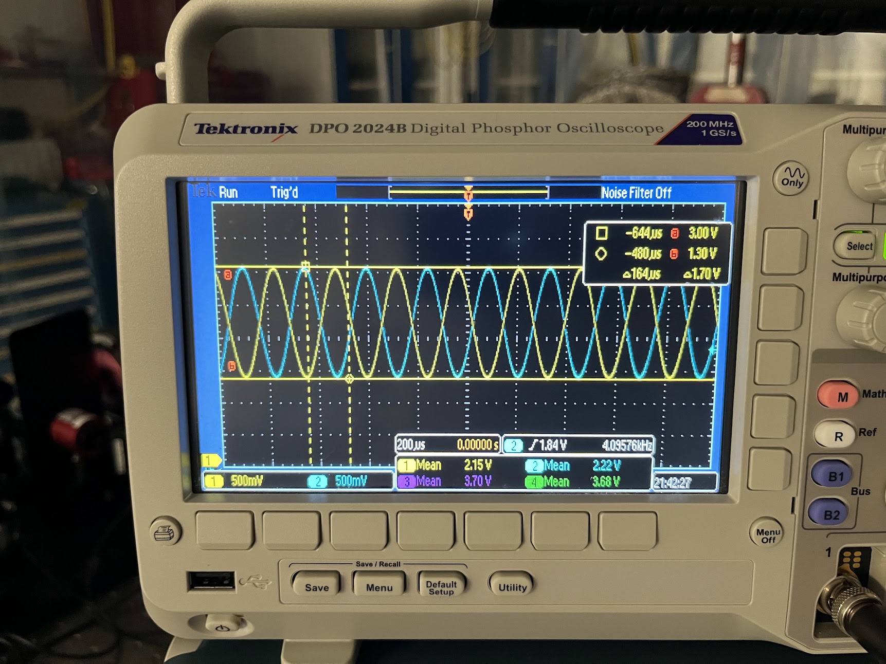
            Max = 3.00 [V]
            Min = 1.30 [V]
            Amp = 1.70 [V]
            Mean = CH1 2.15 [V], CH2 2.22 [V]
            Efficiency = Amp / (2*mean)
	        CH1      1.70/(2*2.15)= 0.395 % yuck!
	        CH2      1.70/(2*2.22)= 0.383 % yuck! 
        . But this is just a "reading off the scope" efficiency, wanted to make sure this wasn't dramatically influenced by dark offsets, so spend some time gathering PD DARK offsets. All SPD dark offsets are in the 15 [mV] level FAR below the now-excellent signal voltage levels.
        . Also noticed, with both IFOs functional and up on the o-scope, with it triggered on the REF IFO,
            :: Phase drift of MEAS IFO w.r.t. REF IFO.
            :: Sensitivity of the IFOs to flicking of either MEAS or REF fiber.
    - Resolving to take this offline to talk to the SPI crew about it, I re-dressed up all cabling.
        . Found picomotor cable was mounted in the Cable Table bracket upside down, making the map of which quadrupus leg goes to which pico-actuated mirror challenging, so I fixed that.
        . Hooked them up as designed (mirror names == D2400107; pico cable == D2400342; pico driver board D1100326):

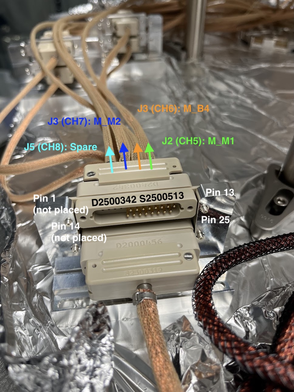
            :: M_M1  > J2  > Pins 12,13,24,25 > furthest right when looking at the open D25 connector as the boat floats (with all pins to the left) > Pico Driver page 5, D25-J2 CH5 
            :: M_B4  > J3  > Pins 10,11,22,23 > 2nd right > Pico Driver page 5, D25-J2  CH6
            :: M_M2  > J4  > Pins 8,9,20,21   > 2nd left  > Pico Driver page 5, D25-J2  CH7
            :: Spare > J5  > Pins 6,7,18,19   > furthest left (where all the missing pins are > Pico Driver page 5, D25-J2  CH8
        . Confirmed all cables went "up first," with a soft-bend to breadboard level, and completely clear of all beams.
        . Confirmed IFO_MEAS_A cable is neatly threaded through the middle of the periscope mirrors, but doesn't interfere with the mechanical motion of the periscope
        . Confirmed all cables were clear of -X perimeter so as to not interfere with installation shelf cylinders D2500142
        . Confirmed all cables were clear of the utility holes consumed by SLIC shroud D2400106
        . Confirmed all cables won't interfere with installation handles
        . Confirmed all cables won't interfere with attaching / reattaching optical fibers.

But at least, the victory from today is : The D2400107-v4 board is completely migrated over to the D2400107-v5

At the end of the day the board was completely migrated, but I now had a list of issues to now tackle ([FUTURE JEFF] prioritized by importance):
    (1) Low efficiency of REF IFO.
    (2) Beam dump for QPDB. Is this good enough? How can I test quantitatively? Could move rotate the housing back, but -- won't the position of this reflected beam change once we get the real return MEAS beam, and we want "if centered on the QPD, then IFO will heterodyne" as an alignment reference?
    (3) Breathing of heterodyne efficiency on MEAS IFO (only MEAS IFO, REF IFO is rock-soiid).
    (4) P-pol transmission dependent on physical position of optical fiber
    (5) Reflection of PWRIN_REF. Should I crack the enclosure to try to fix it?
    (6) Phase drift of MEAS IFO w.r.t. REF IFO.
    (7) Sensitivity of the IFOs to flicking of either MEAS or REF fiber.

[FUTURE JEFF] After discussing with the team (in order of how to address the issues): 
    (4) Fiber polarization state output dependent on fiber position. Check the tiny set screws on the fiber collimator again, make sure they're secure, but not too secure.
    (2) QPDB reflection dumping. I didn't follow procedure here, and that has caused a ripple effect. Fixing M_M1 alignment into QPD B is the way to go. That should solve the QPD B reflected beam issue, and thus any potential for clipping, and might clean up (3), BUT, before you do that,
    (1) Low REF IFO efficiency might be an issue with the alignment again. 35% is unacceptable, we need both IFOs above 75% at least. Maybe you need to revisit the whole MEAS path alignment, confirming spot position on PWNIN_MEAS, since that confirms M_F1 alignment. If it's off, realign the whole MEAS path and that might clear up the issues with the REF IFO and QPDB. If the PWRIN_MEAS alignment is good, then triple check that you've not put in any optics backwards.
    (5) PWRIN_REF PD reflection dumping. This can be a last issue fixed, but everyone votes to go into the PD and fix it albeit using the utmost of caution to protect the PD.
    (6) Phase drift between MEAS and REF IFOs -- not a big deal. Likely air-currents. Try waiving your hand over the IFO and seeing it you get a wiggle to confirm.
    (7) IFO sensitivity to fiber flicking -- this is why we have two IFOs and subtract the signal, to remove exactly this kind of fiber "acoustic noise" coupling. Nothing to solve here.
    
Images attached to this report
Comments related to this report
jeffrey.kissel@LIGO.ORG - 10:56, Friday 22 May 2026 (90315)
Pictures of the QPD Dumps

- Pic #1 
    QPD alignment signals BEFORE yawing the enclosure, confirming just yaw is the issue.
- Pic #2
    QPD alignment signals AFTER yawing the enclosure.
- Pic #3
    1.16x1.16" "catcher" Beam dumper, prior to moving QPDB enclosure in yaw, looking at IFO_MEAS_B
- Pic #4
    Top down view of D_OL_QPDB prior to moving QPDB enclosure in yaw.
- Pic #5
    Views of 1.58" x 1.58" after installation.
- Pic #6
    Beam position on "catcher" dump plate.
- Pic #7
    View of tight clearance of beam into IFO_MEAS_B.

DON'T DO THIS, JEFF.
Images attached to this comment
jeffrey.kissel@LIGO.ORG - 11:09, Friday 22 May 2026 (90316)
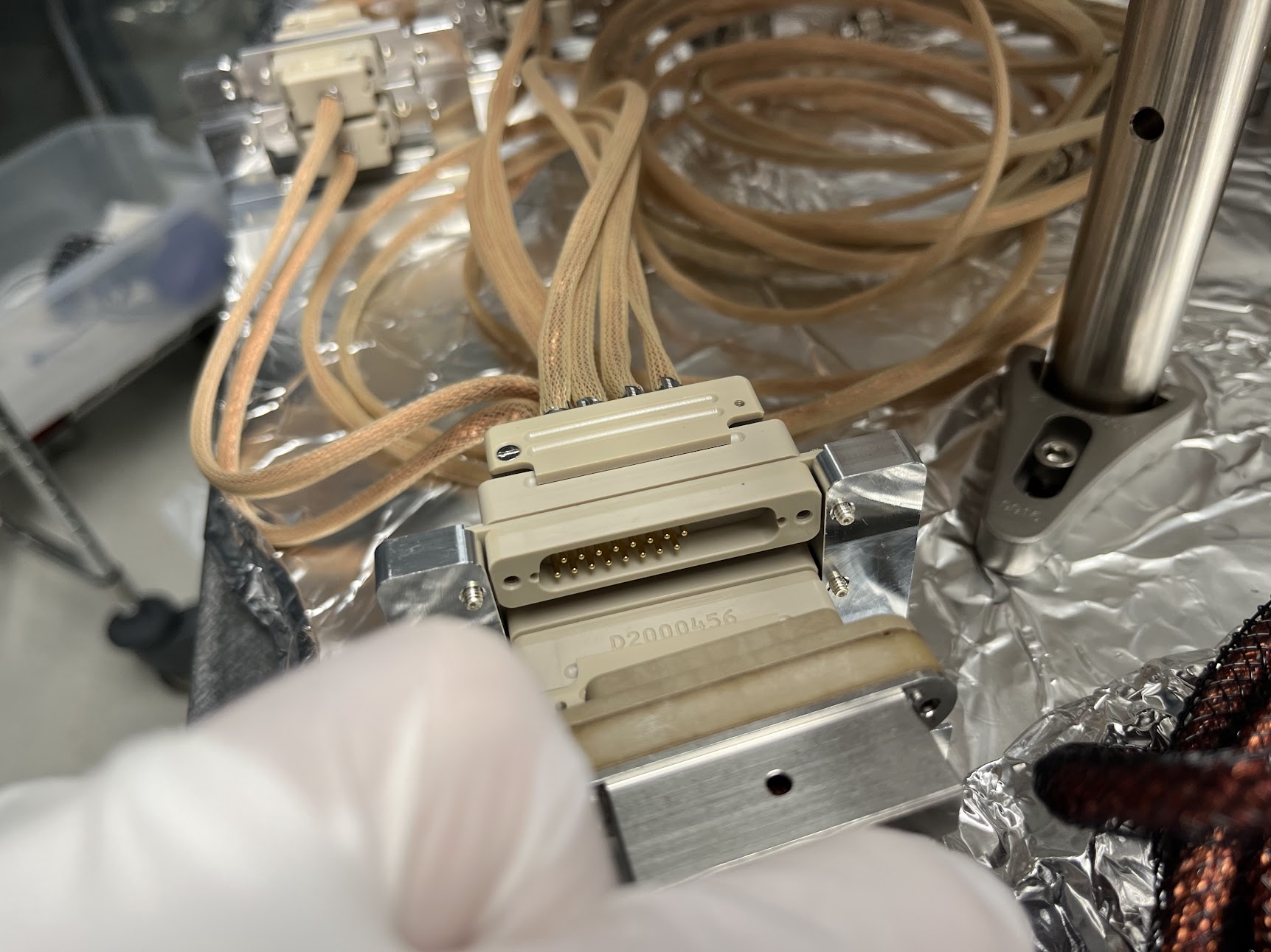
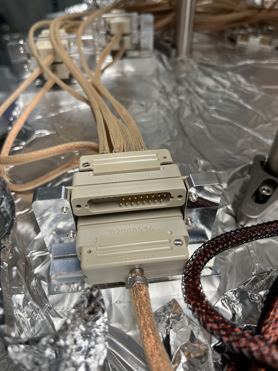
Pics of Picomotor Quadrapus D25 Orientation Flip:

This is of the Quadrapus D2500342, S2500513.

- Pic #1
    As I found the DB25 end in the Cable Table Bracket, having not been touched since Jim/Bram originally cabled it up on 2026-03-19.
- Pic #2
    After flipping the DB25 end in the CTB.
- Pic #3
    Same as Pic # but labeled.
Images attached to this comment
jeffrey.kissel@LIGO.ORG - 11:20, Friday 22 May 2026 (90317)
Pics of MEAS IFO efficiency drift / changes over time

Here's some photos showing the "drift" in efficiency I'm talking about.
The first three photos: IFO BeatNote (400e-6 [sec/DIV]), InputPower, and NPRO Power.


The second three photos show the same thing 15 minutes later, with no change to the system but the efficiency is restored to the ~72%: IFO BeatNote (400e-6 [sec/DIV]), InputPower, and NPRO Power

The last three photos show the time-zoomed out 400 [sec] trends (40 [sec/DIV]) of the MEAS IFO efficiency as I was aligning the REF IFO, one at 10:56a and one at 11:19a PDT. 
Images attached to this comment
H1 AOS (SEI)
shoshana.apple@LIGO.ORG - posted 09:59, Friday 22 May 2026 - last comment - 13:09, Saturday 23 May 2026(90314)
CRS build continues
[Shoshana, Ryan S]

Yesterday we began building the second set of CRSs sent over from LLO (mostly just putting in heli-coils). I (Shohana) will probably continue working on them today

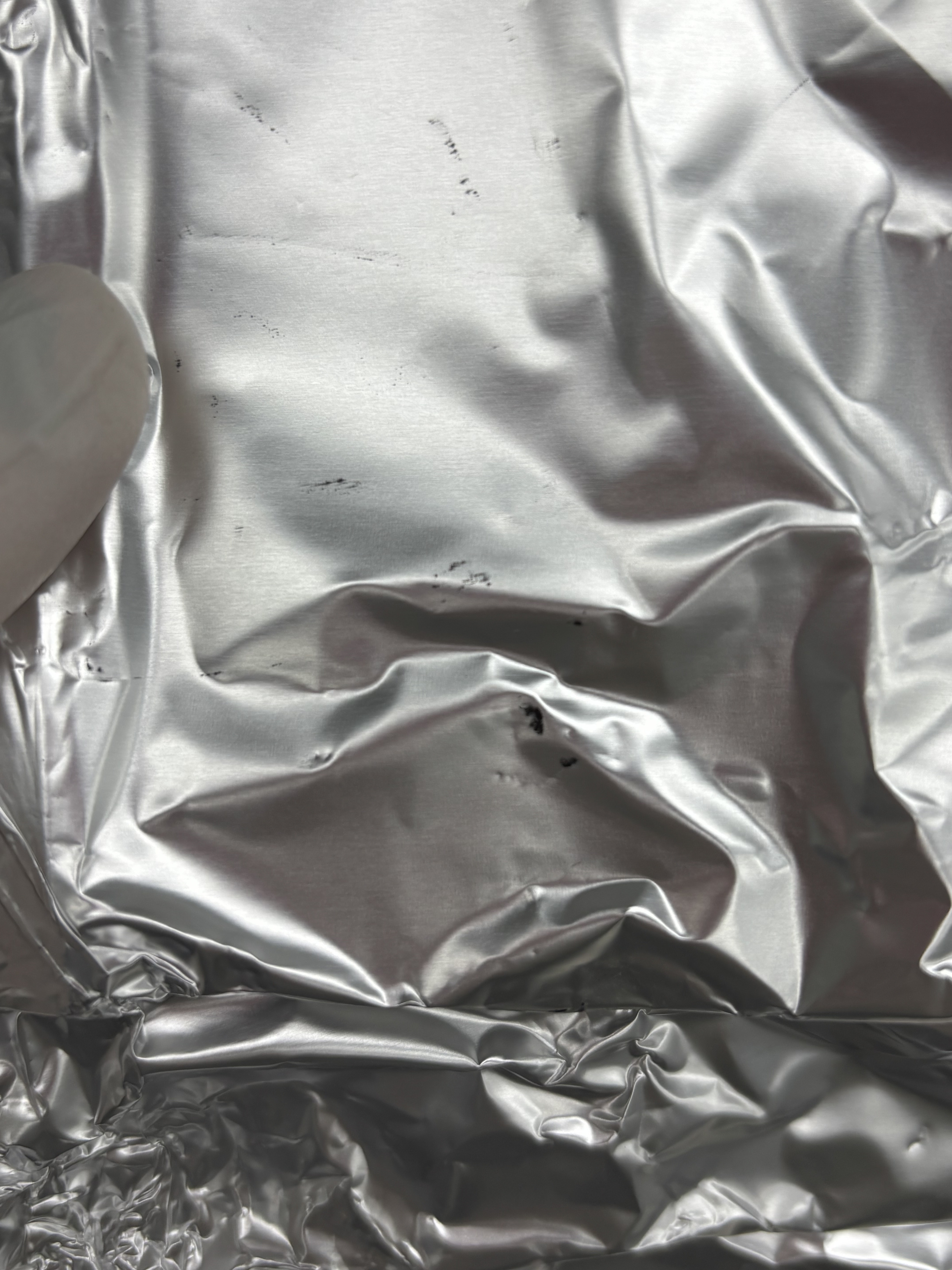
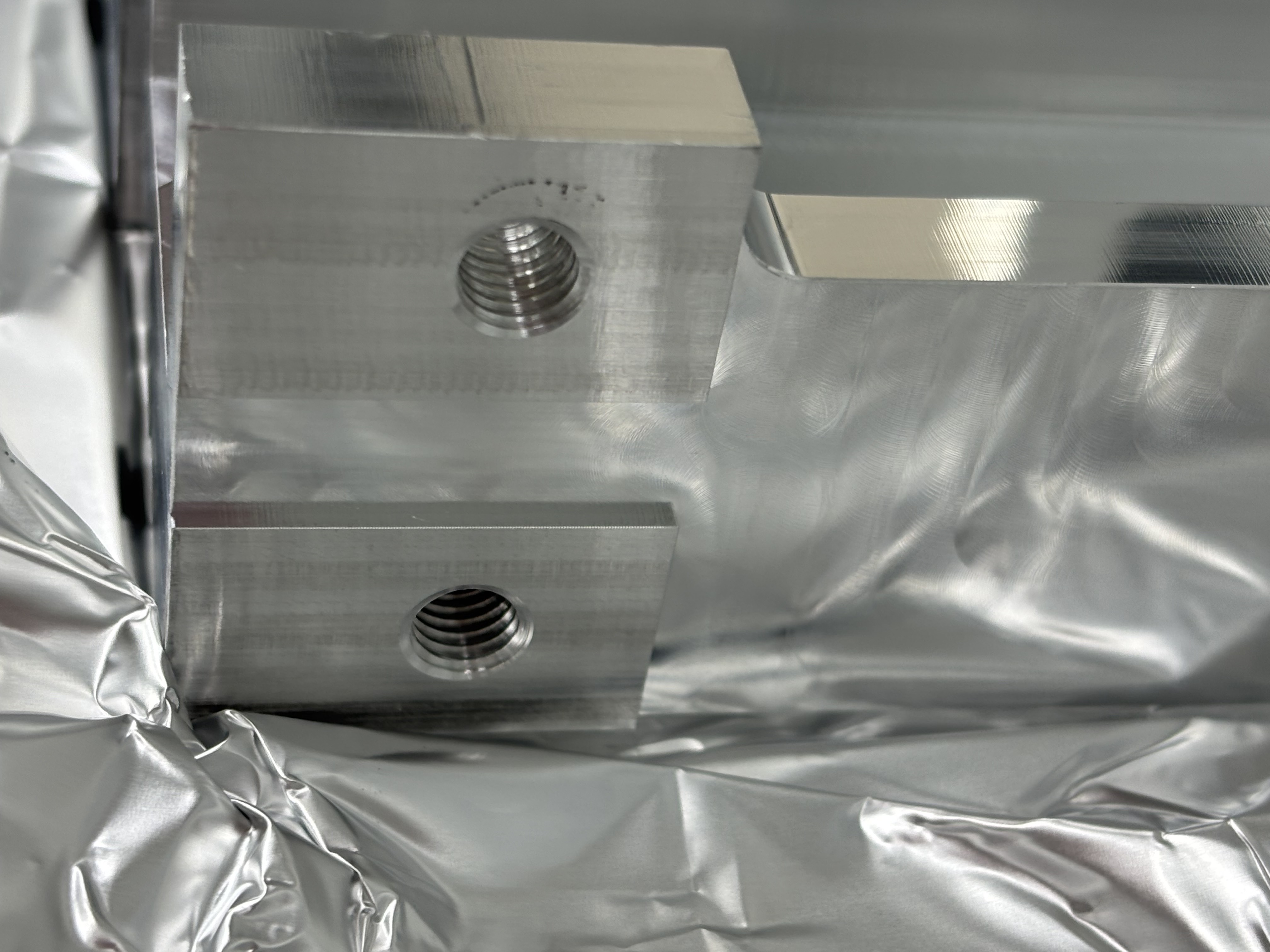
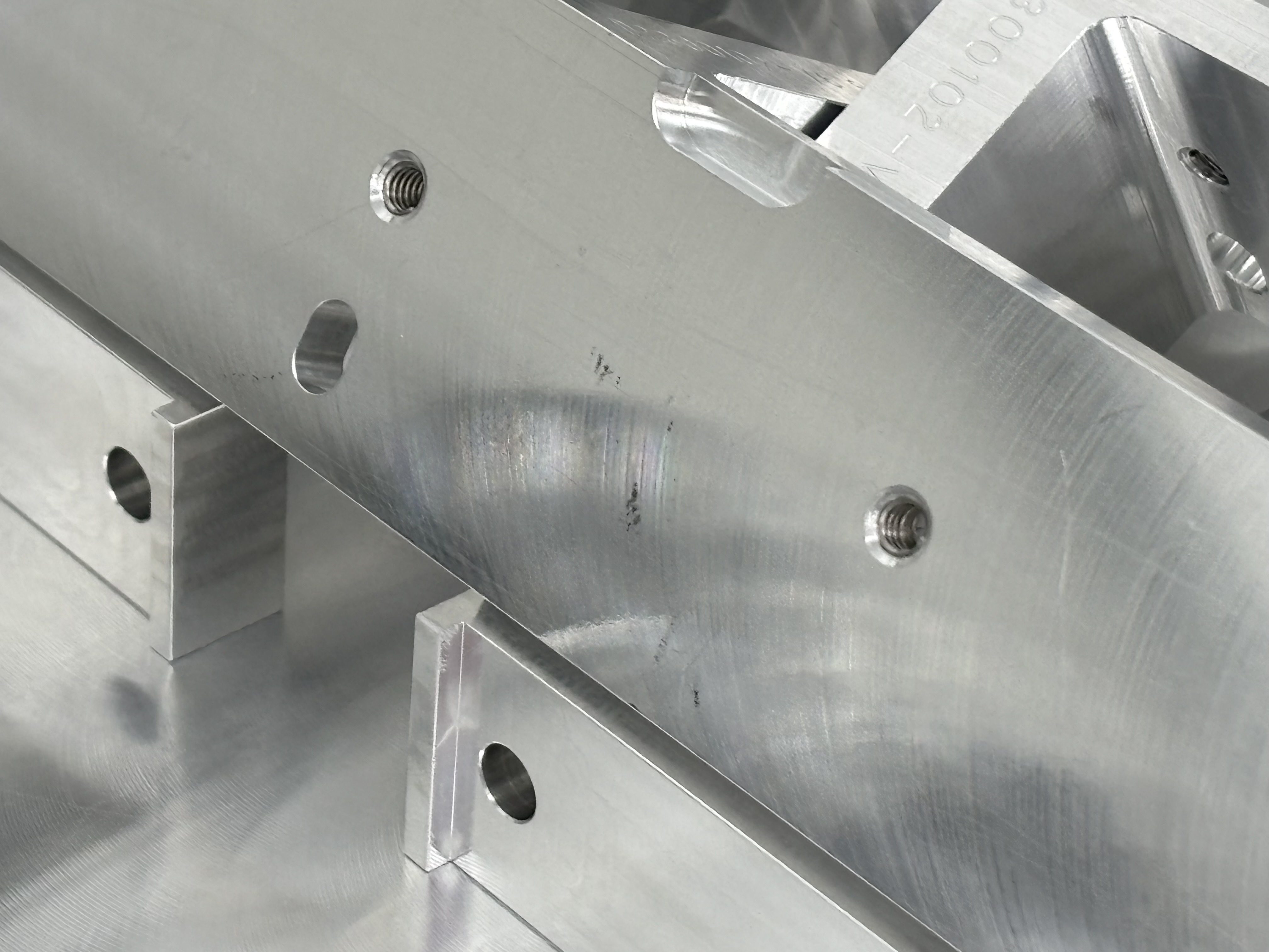
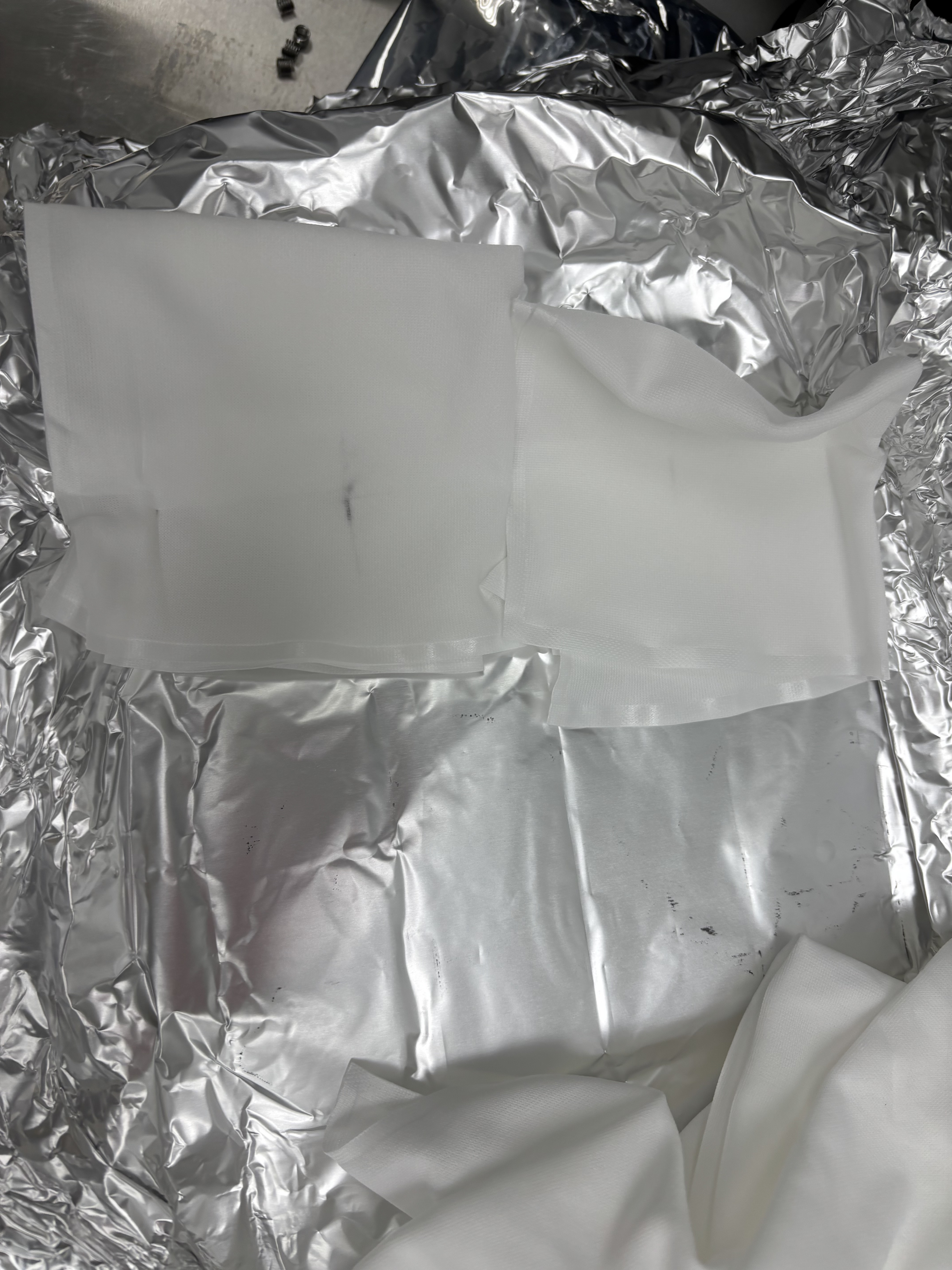
For some of the parts sent over from LLO (where they had already gone through clean and bake) we found some black residue in some of the aluminum foil wrappings and on the parts (specifically the cross beams [D2300102] and the solid supports [D2300144]) some of which would come off when wiped, but some of the residue would not. Pictures below

Images attached to this report
Comments related to this report
shoshana.apple@LIGO.ORG - 16:49, Friday 22 May 2026 (90326)SEI
[Shoshana]
Continued LLO CRS build
One of the CRS Legs [D2300089 SN016] has a threaded hole on the side where the threads do not go deep enough for a helicoil to be fully inserted, and ends the helicoil up sticking out by ~1/8 inch, meaning half of one of the CRSs cannot be fully built right now unless the hole is tapped deeper a shorter helicoil is used.
There were no other issues and 1.5 of the extra CRS supports are built

The clean and bake team at Livingston says the residue is just aluminum oxide and not an issue
arnaud.pele@LIGO.ORG - 13:09, Saturday 23 May 2026 (90331)

Which threaded hole is it ?
If the hole depth is correct, but we're just missing the threads on the bottom part of the hole we can tap it with a clean tool.
Alternatively we can also order a 1D helicoil.

H1 IOO (INS, IOO, ISC)
keita.kawabe@LIGO.ORG - posted 17:29, Thursday 21 May 2026 - last comment - 11:25, Thursday 28 May 2026(90295)
Beam positions in HAM2 and some thinking (Rahul, Elenna, Keita)

(I learned from T0900486 "IO Stray Light Analysis and Baffle Design" that the IFI input baffle is called HA3, IFI output baffle is HA6, the baffle right in front of IM4 is actually supposed to be a pair of HA12-a and HA12-b but there's only one baffle which I suppose is HA12-a, two-hole baffle for ISS array is HA11, and the last IFO REFL before the beam leaves HAM2 is HA13.)

Clipping on the IFI input baffle (HA3) might not be real

The beam spot on this baffle was OK before we did anything to IM1 on Tuesday (IFIinput_before.jpg). It's low and toward +X, but nowhere near clipping.

This baffle is right in front of the calcite wedge that deflects the IFO REFL beam away from the incoming beam path from IM2 (HA3_calcite_wedge.png). The lever arm from the wedge to the baffle looks to be an inch or so at most. Hard to imagine that the REFL is clipped while forward going beam is not, but the scattering goes away when I block the beam between PRM and IM4.

The reported "IFO REFL beam clipping" on this baffle is either because the PRM is not retroreflecting, or maybe it's some kind of ghost beam produced from the PRM reflection somewhere.

If we establish that the main IFO refl is NOT clipped when PRM retroreflects, we don't have to worry about this baffle too much (though ghost beam is still a problem).

We will have to bring a card with a hole to make sure that the beam is retroreflected as good as we can.

FYI, IFIinput_aftercentering.jpg shows the same baffle after we made a huge change in IM1.

We THINK that the beam on the IFI output baffle (HA6) is OK too but we need to check

We don't have any good view of that baffle so it's hard to assess, and we forgot to check it before making changes to IM123.

However, given how small the change was on IFI input baffle, we don't expect that it was very bad before. We'll have to revisit and confirm.

IMC beam spots

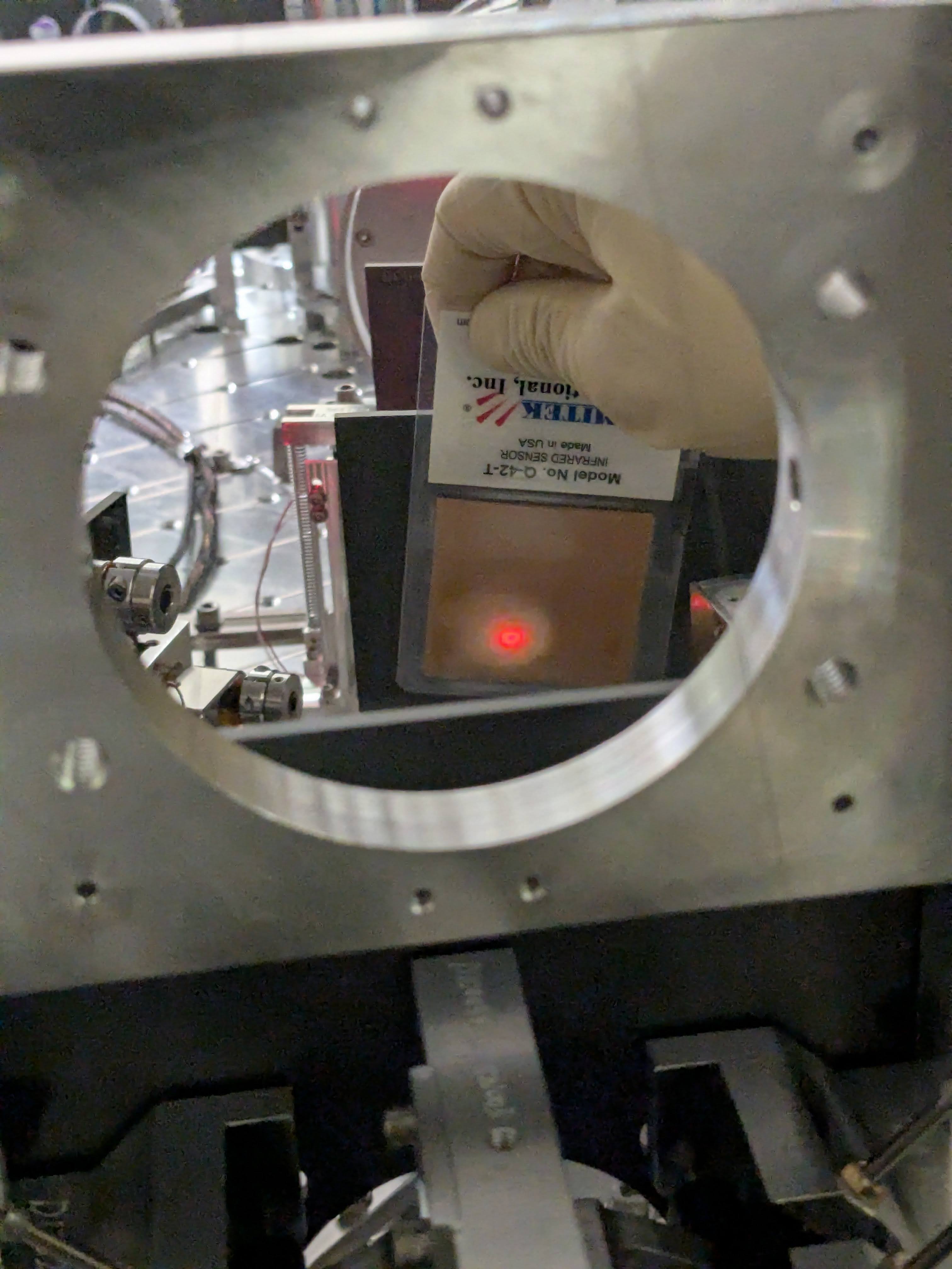
As of now, the measured beam position in front of MC mirrors are as follows this. For measurement points, see mc_beampos_measurement_cartoon.jpg. The height is pretty good for all. MC3 is great horizontally too. Beam spot on MC2 and MC1 are both shifted in -Y direction.  MC2 by 3.6+-1mm, MC1 by a couple +-1mm.

  Height from ISI measured [nominal] Horizontal shift in Y direction from the nominal beam position
MC1 154.3 +- 1.3 [155.5] -1.9 +- 1
MC2 167 [166.7] -3.6 +- 1
MC3 154 +- 0.5 [155.5] +0.3 +- 1

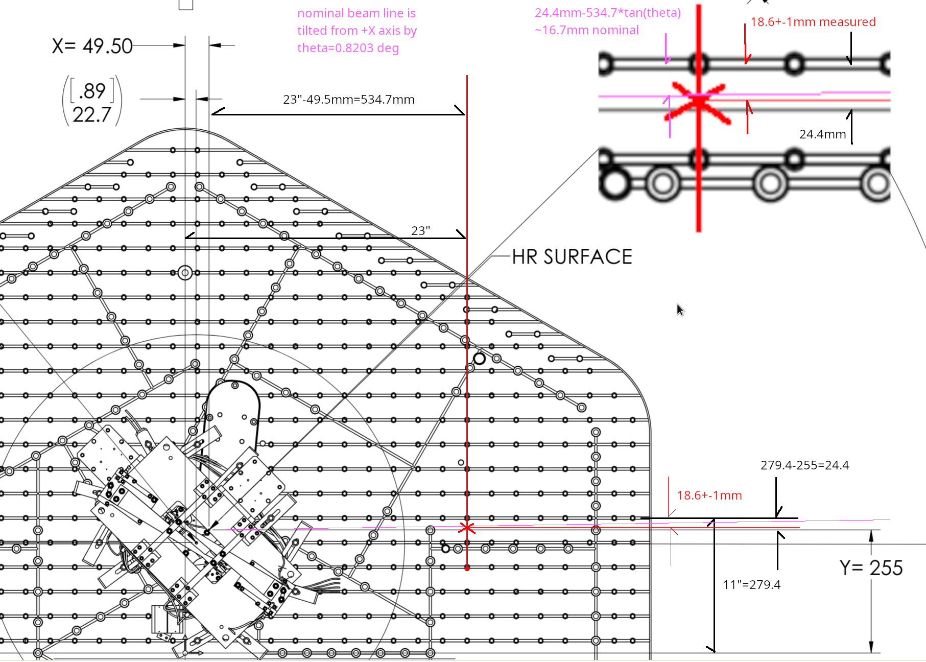
Horizontal positions were determined by covering half of the beam with a vertical hard edge (ruler etc.) and then measuring the position of the edge relative to the neighborhood screw holes using a small ruler, and then using the drawings (D0901088, D901089, D0901099) as well as other IO documents (e.g. T0900486) to figure out the nominal beam location. As an example of tedious work done, see ham2mc1.png. Due to the way it was done, we cannot determine the horizontal position of the beam much better than maybe 1/2 of the beam radius. I just put +-1mm error for all measurements. Height numbers were measured off of a ruler, the error bar (if any) is the difference between Rahul's reading and mine divided by two.

What if we move MC2 or MC3 beam spots (or both) to unclip IM4 baffle (HA12)

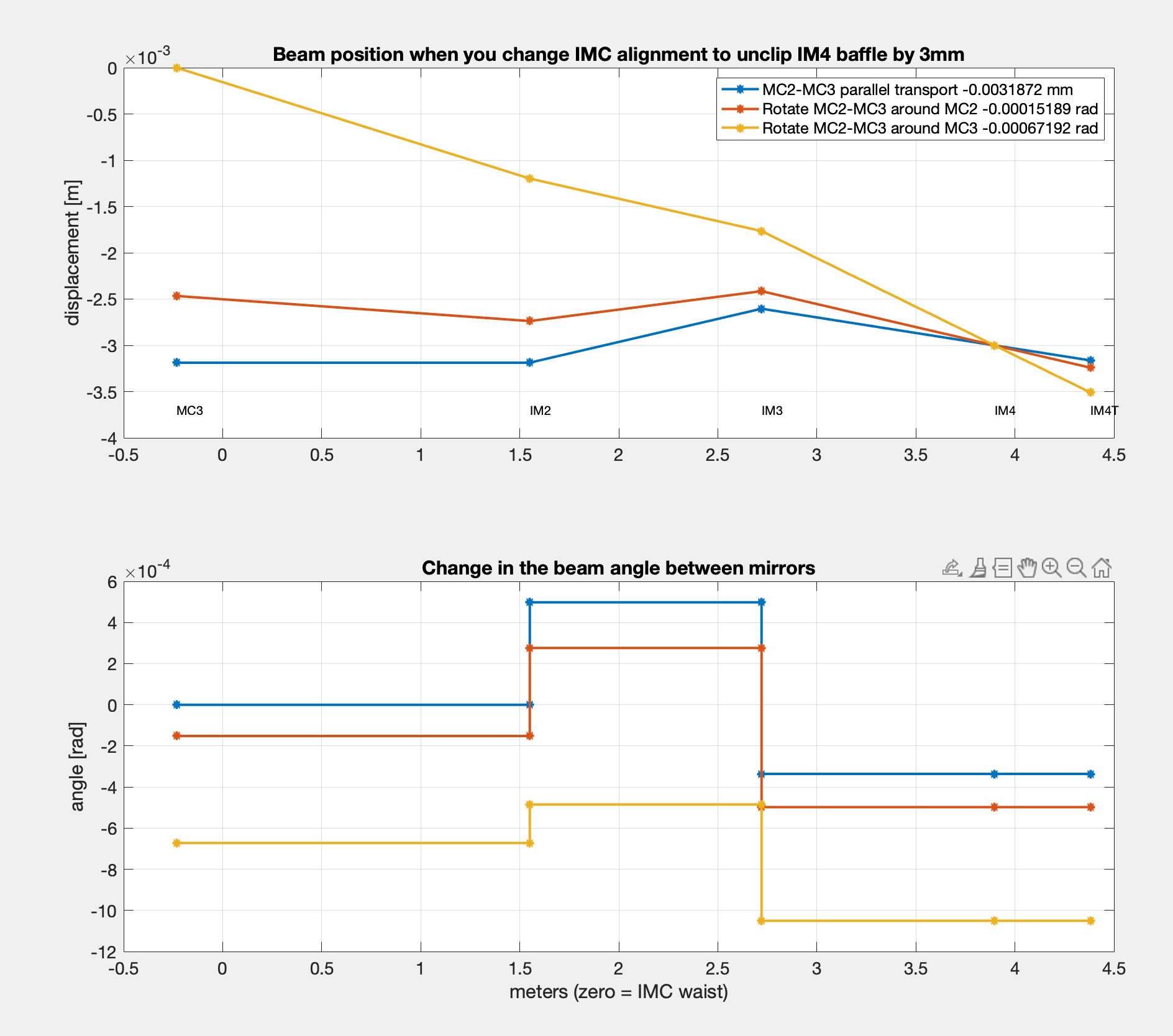
To get more sense of magnitude of IMC motion relative to the beam motion on IM4, I calculated how much the IMC alignment should be changed to move the beam on IM4 by 3mm in -Y direction (comfortably far from clipping but not enough to center) without moving IMs.

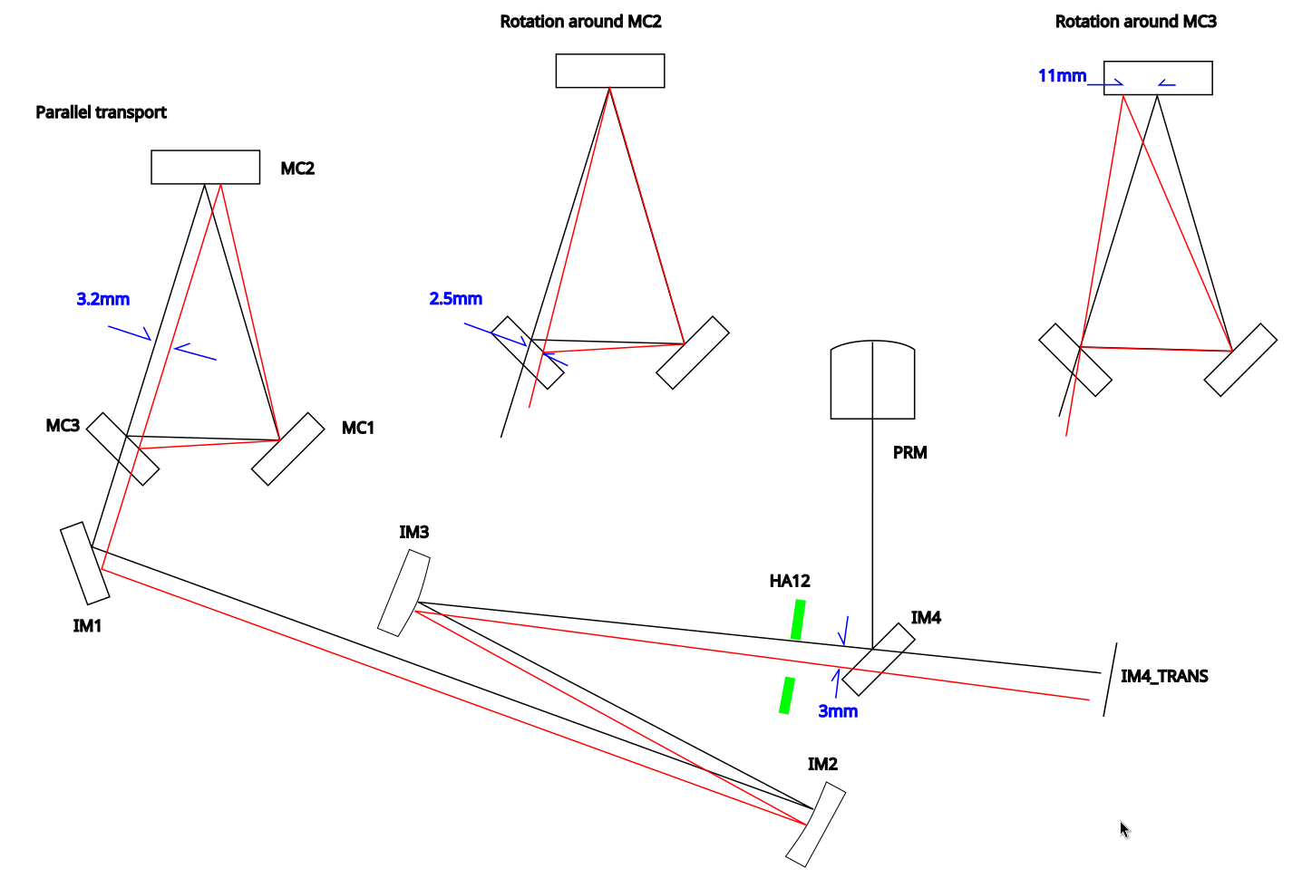
There are many linear combinations of the MC3 spot position and the angle of the beam coming through MC3 that will move the beam on IM4 by 3mm, so I just chose "parallel transport of MC2-MC3 line" (i.e. no angle change of the angle of the beam coming out of MC3), "rotate MC2-MC3 line around MC3" (i.e. no beam displacement on MC3) and something in-between ("rotate around MC2").

See cartoon_IMC_alignment_to_unclip.png (not to scale but the sign of displacement/rotation is correct along the entire path) and IMC_to_unclip_HA12.png (actual calculation). IMC is not the only thing that moves, we can also move IM2, but anyway. In the "parallel transport" case the beam will be move further away from the center of MC2 (remember it was already 3.6+-1mm in -Y direction to start with so the end result will be 6.8+-1mm in -Y direction). OTOH in the "rotation around MC3" case, the beam on MC2 will move by 11mm in +Y direction so the end result will be 11-3.6+-1=7.4+-1mm in +Y direction.

In all cases the beam will likely still hit the IM4_TRANS because the QPD (Excelitas C30845) has a huge 8mm active diameter, but it will likely be completely in one quadrant. So all of these will be bad solution if we believe that the IM4_TRANS position should be close enough.

Note that the "rotation around MC3" case will result in about 1mrad beam angle change on IM4. This needs to be absorbed by IM4 rotation by about 500urad to send the beam to PR2. 

It's also worth noting that IM4-PRM HR distance is almost the same as IM4-IM4_TRANS distance.

What if we fix the beam on IM4_TRANS?

Instead of IMC alignment, now let's think about the beam positions from the end point (IM4_TRANS).

Again, assume that we want to keep the IM4 TRANS beam position. We tried two different IMC alignment, and the beam was clipped on IM4 baffle (HA12) after bringing the beam back to the target IM4 TRANS position.

Moving the beam position on HA12 by 3mm in -X direction without changing the IM4_TRANS position means that we shift the beam position on IM3 by about 8mm. IM3-IM4 path beam angle changes by 4.8mrad counter-clockwise. This is an absolutely huge change. 

PRM should be moved by 2.4mrad, and 8mm on IM3 is already the radius of IFI output baffle (HA6)  so we'll be worrying about clipping there. There seems to be no solution where the beam is far enough from the IM4 baffle (HA12) edge AND the beam is on the same position on IM4_TRANS as in vacuum. 

As far as we assume that IM4_TRANS is trustworthy, it's very likely that the beam was clipping or at least very close to clipping on HA12 in O4.

However, if IM4_TRANS path moved after HAM2 was opened (i.e. somebody bumped something), IM4_TRANS position as of now doesn't mean anything. We have to at least grab and wiggle the steering mirror as well as the QPD for that path to make sure that nothing is loose. (I already did that test for MC2 TRANS, and they didn't move.)

Images attached to this report
Comments related to this report
keita.kawabe@LIGO.ORG - 17:42, Thursday 21 May 2026 (90305)

Attached are an example of beam position measurements (in this case MC1).

Images attached to this comment
keita.kawabe@LIGO.ORG - 13:41, Friday 22 May 2026 (90321)

IM4_TRANS path optics (pickoff for the ISS path, pico for IM4_TRANS centering) as well as the IM4_TRANS QPD itself seemed to be firmly attached to the pole and the ISI table. I grabbed them using my hand and wiggled and they didn't move at all.

keita.kawabe@LIGO.ORG - 17:23, Friday 22 May 2026 (90327)

PIT angle of the beam from IM4 to PRM AR to PR2

The beam is level between IM1 and IM4 and then goes up toward PRM, but I cannot easily find how much. So here's a quick note.

  MC3 IM1 IM4 PRM AR PRM
Height [mm] 155.5 155.5- 155.3   158.8
Angle [rad] of the exiting beam relative to the horizontal plane   level 8.5m 628u 628u

Nominal height of MC1 and MC3 center is 155.5mm (D09010088, D0901089). IM1 beam height should be pretty close though MC2-MC3 line is not level.

The beam from PRM HR to PRM is tilted up by 0.035966 deg = 628urad (I'm using the PIT angle of PRM itself in  D0901920 rather than reading the coordinates of PRM and PR2).

PRM has 1 degree vertical wedge (D0901172), the bottom being widest, so the beam is tilted up from IM4 to PRM AR by ~(n-1)*1deg = 0.4497 deg relative to the PRM-PR2 line, n being the refractive index of fused silica for 1064nm (1.4496).

The beam from IM4 to PRM AR is therefore tilted up by (0.4497+0.035996) = 0.4857 deg = 8.5 mrad relative to the horizontal plane.

PRM center height is 158.8mm nominal (D0901090) and the distance from PRM AR to IM4 is 415.9mm (T0900486), so the beam height at IM4 should 158.8-415.9*8.5mrad = 155.3mm, which is good enough of an agreement with MC3 height.

FYI I measured the IM4 baffle height this morning and it was (206+104)/2 =155mm, so the baffle height should be correct. (The beam is low on that baffle though YAW is the worse problem than PIT.)
keita.kawabe@LIGO.ORG - 11:25, Thursday 28 May 2026 (90336)
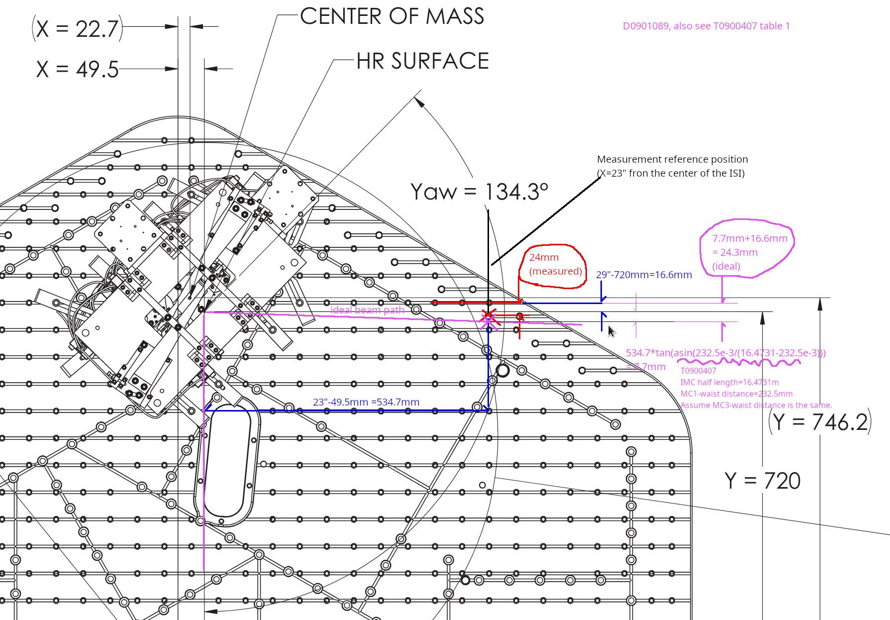
This is the beam position measurements for MC2 and MC3.

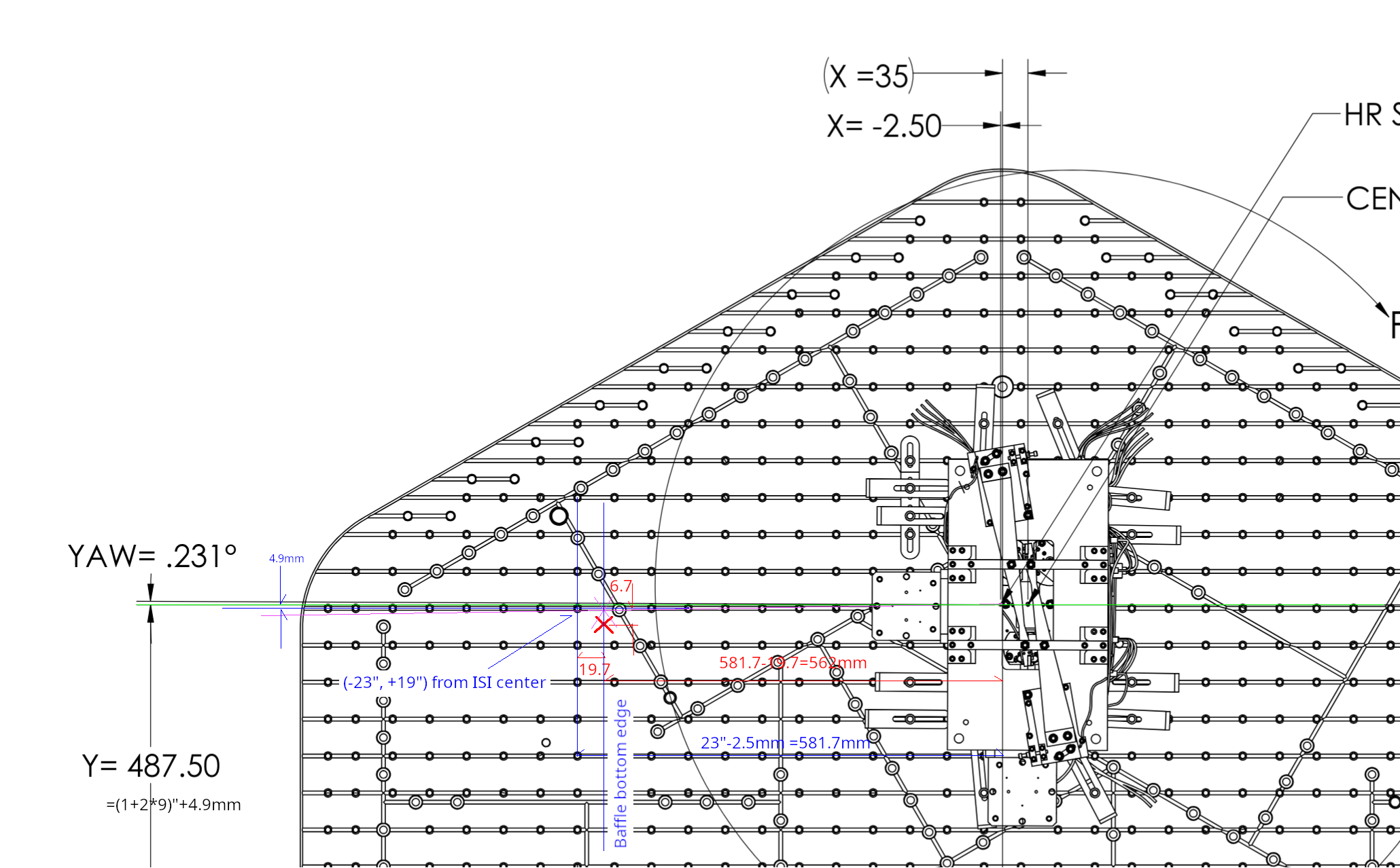
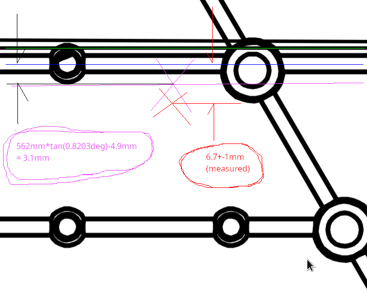
Note: In D0901099-V2 on page 9, it looks as if MC2 HR surface is supposed to be rotated by 0.231 degrees clockwise seen from the top.

I don't think that makes sense unless the ISI table itself is supposed to be rotated 0.231 degrees counter-clockwise because the IMC is an isosceles triangle, MC1-MC3 line is parallel to Y axis and MC2 Y coordinate is the mean of MC1 and MC3 Y coordinate according to the global coordinates of MC1, MC2 and MC3 (E1100494-V4, E1100494-V6).

I assume that the ISI tables aren't nominally rotated around local Z axis.

  Global X Global Y Global Z
MC1

-20,072.0

255.0

-97.3
MC2 -3833.1 487.5 -87.3
MC3

-20,072.0

720.0

-97.3


Images attached to this comment
H1 SUS
oli.patane@LIGO.ORG - posted 09:55, Thursday 21 May 2026 - last comment - 12:56, Friday 22 May 2026(90300)
BBSS Bouce measurement results (without BRDs)

Ibrahim, Oli

We ran a long overnight Bounce measurement on the BBSS. The BRDs weren't installed for this measurement. AOSEM flags were not installed, and we were 100g heavier at M1 than we are now (this measurements was taken before 90294). 

With those settings in mind, our measurements show that our Bounce mode was at 19.80Hz. The last time these measurements were taken, back in the staging building (88141), the bounce mode with no BRDs was ~19.74Hz, so they're consistant.

The measurement file can be found in  /ligo/svncommon/SusSVN/sus/trunk/BBSS/H1/BS/Common/Data/ 2026-05-19_2200_H1SUSBS_M1M2_BounceNoBRD_V_0p001to40Hz.xml as r13012.

Images attached to this report
Comments related to this report
marie.kasprzack@LIGO.ORG - 12:56, Friday 22 May 2026 (90320)

Attached here is a zoomed in version of this file. The mode is indeed clearly visible in M2 UL, and the frequency is known well enough for proper BRD tuning. Thanks!

The Q of the mode seems to be about 3400. Maybe a higher excitation would be possible to get a better definition. Were you at the saturation limit to drive M1 V?

Images attached to this comment
Displaying reports 601-620 of 88344.Go to page Start 27 28 29 30 31 32 33 34 35 End