FAMIS27798
I ended up not adding any water to either of the chillers since they both looked near the top of their range. The filters looked good, both the mesh and socks. The dixie cup was dry. Sheet updated.
TITLE: 09/19 Eve Shift: 2330-0500 UTC (1630-2200 PST), all times posted in UTC
STATE of H1: Observing at 156Mpc
OUTGOING OPERATOR: TJ
CURRENT ENVIRONMENT:
SEI_ENV state: CALM
Wind: 14mph Gusts, 9mph 3min avg
Primary useism: 0.02 μm/s
Secondary useism: 0.10 μm/s
QUICK SUMMARY: H1 just made it back to observing minutes before the start of my shift following what sounds like a straightforward reacquisition.
Closes FAMIS 26009
Nothing looks out of the ordinary/weird and measurements are comprable to the last weekly check done (alog 80081)
This one has our normal ETMX glitch and a slight DARM wiggle, but we still have no idea why.
Observing 2259UTC. Full auto relock.
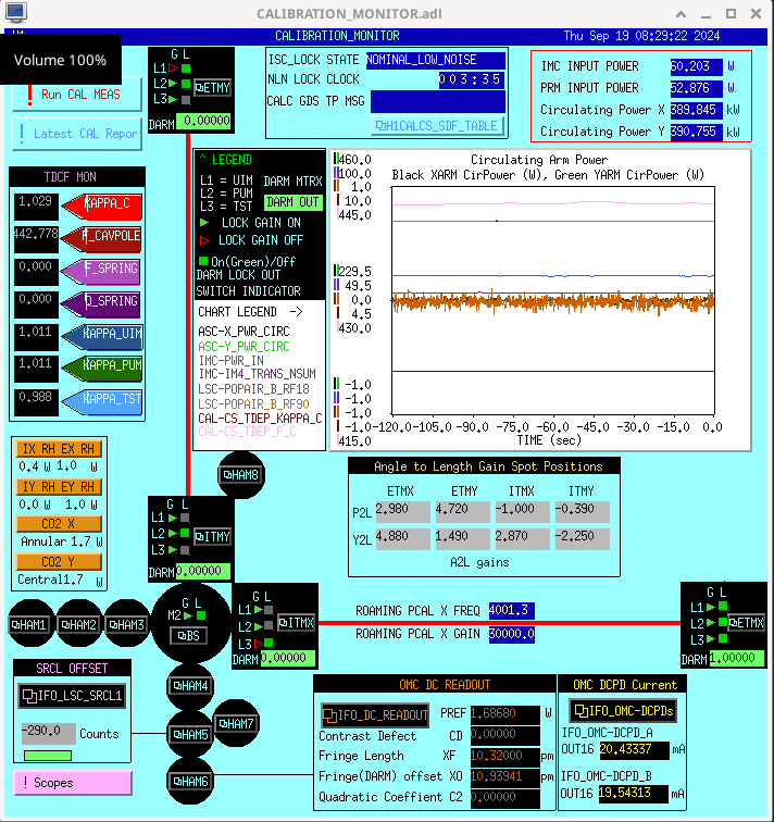
Vicky, Camilla, Naoki, Sheila
After our first trial of running ADS for OMC 3 MHz to align ZM5+6 (80114), we came up with a hypothesis of why this didn't maximize squeezing. We are trying to maximize the 3MHz Q signal, while the I signal is servo's. Changing the demod phase of the 6MHz rotates the IQ ellipse, in general anti-squeezing is at the demod phase where Q is maximized and squeezing is near the phase where Q is minimized, but because the 3MHz is off resonaonce in the OPO the best squeezing is slightly away from the minimum.
If alignment changes didn't change the squeezing angle (for a fixed demod phase), then running ADS to maximize the 3MHz Q signal should be increasing the throughput of 3MHz, which would mean that the OPO is better aligned to the OMC. But, we see that changing the alignment changes the squeezing angle. This means that moving the alignment to maximize RF3 would only work as an alignment servo if the RF3 demod phase were updated to keep the squeezing angle constant.
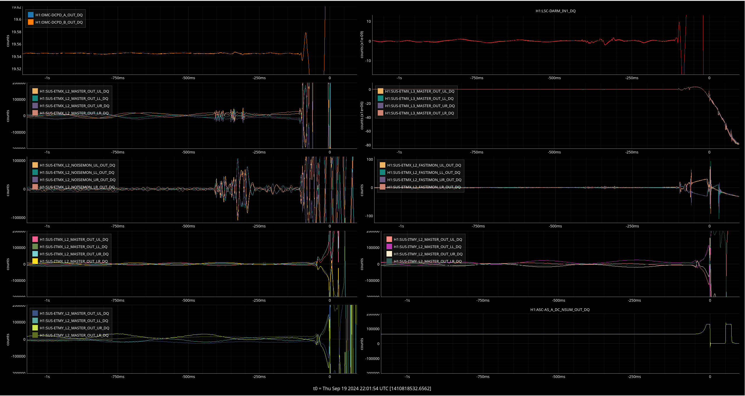
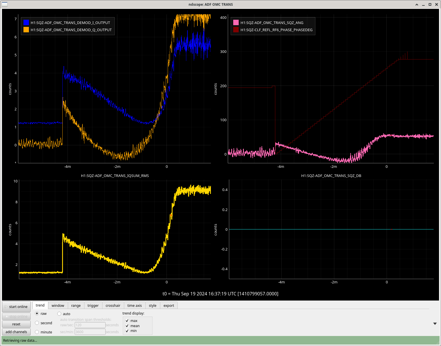
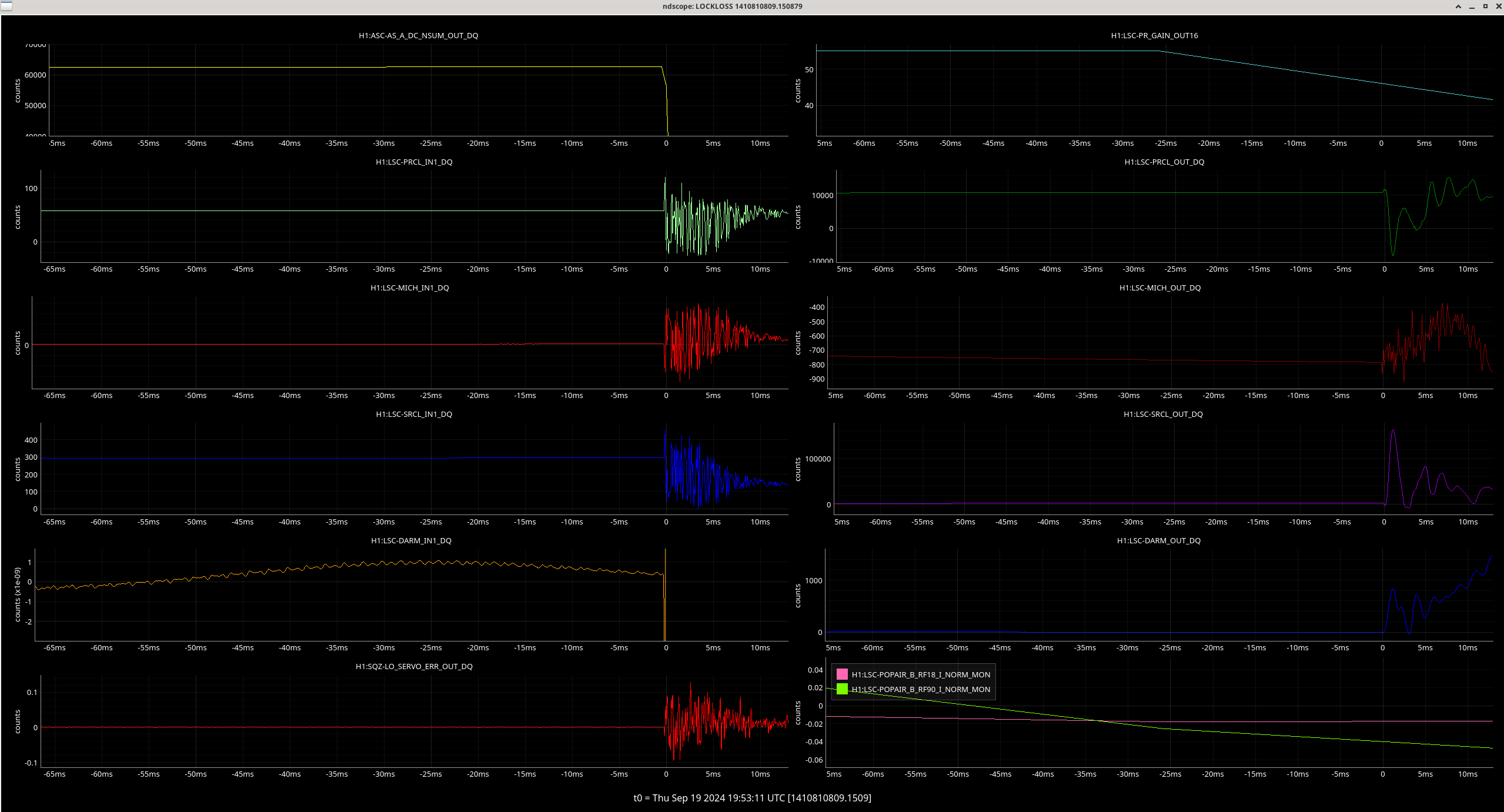
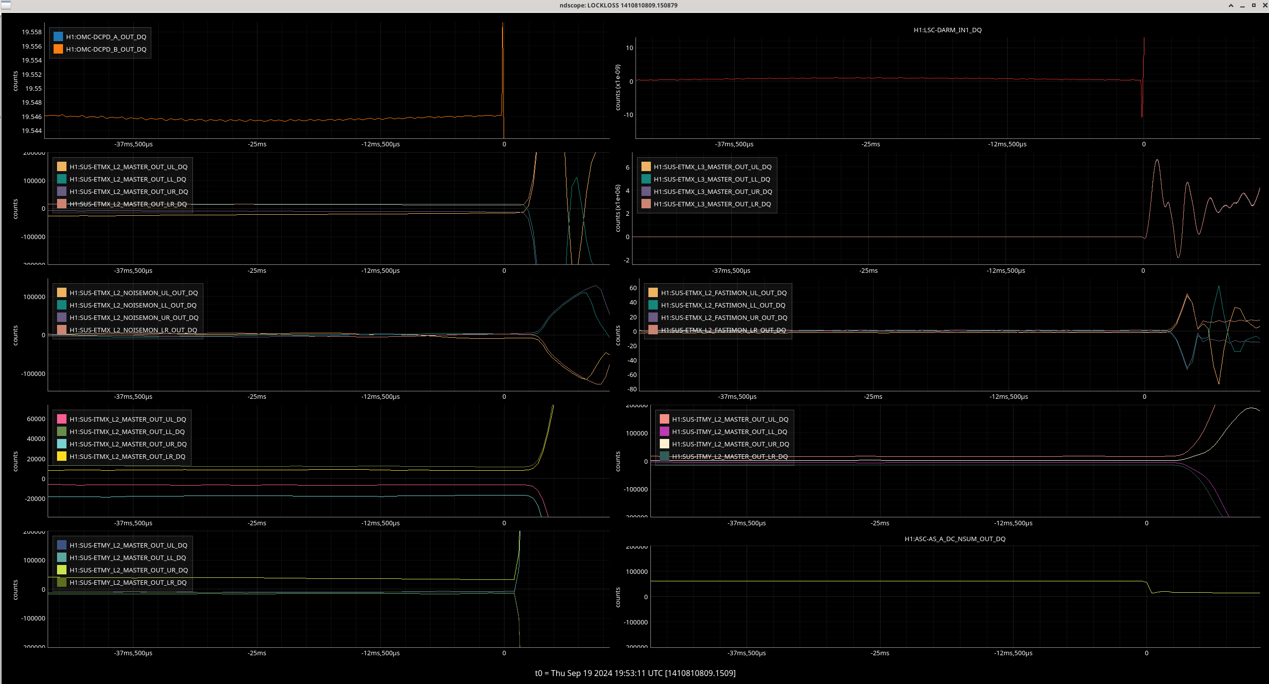
So our plan for today was to run the ADF servo to feed back to RF6 demod phase and keep the squeezing angle correct while we run ADS to adjust the alignment of ZM5+6. The servos worked fine, but again didn't give us good squeezing. We think this is because the ADF servo didn't actually do a good job of keeping the squeezing angle set to minimize shot noise.
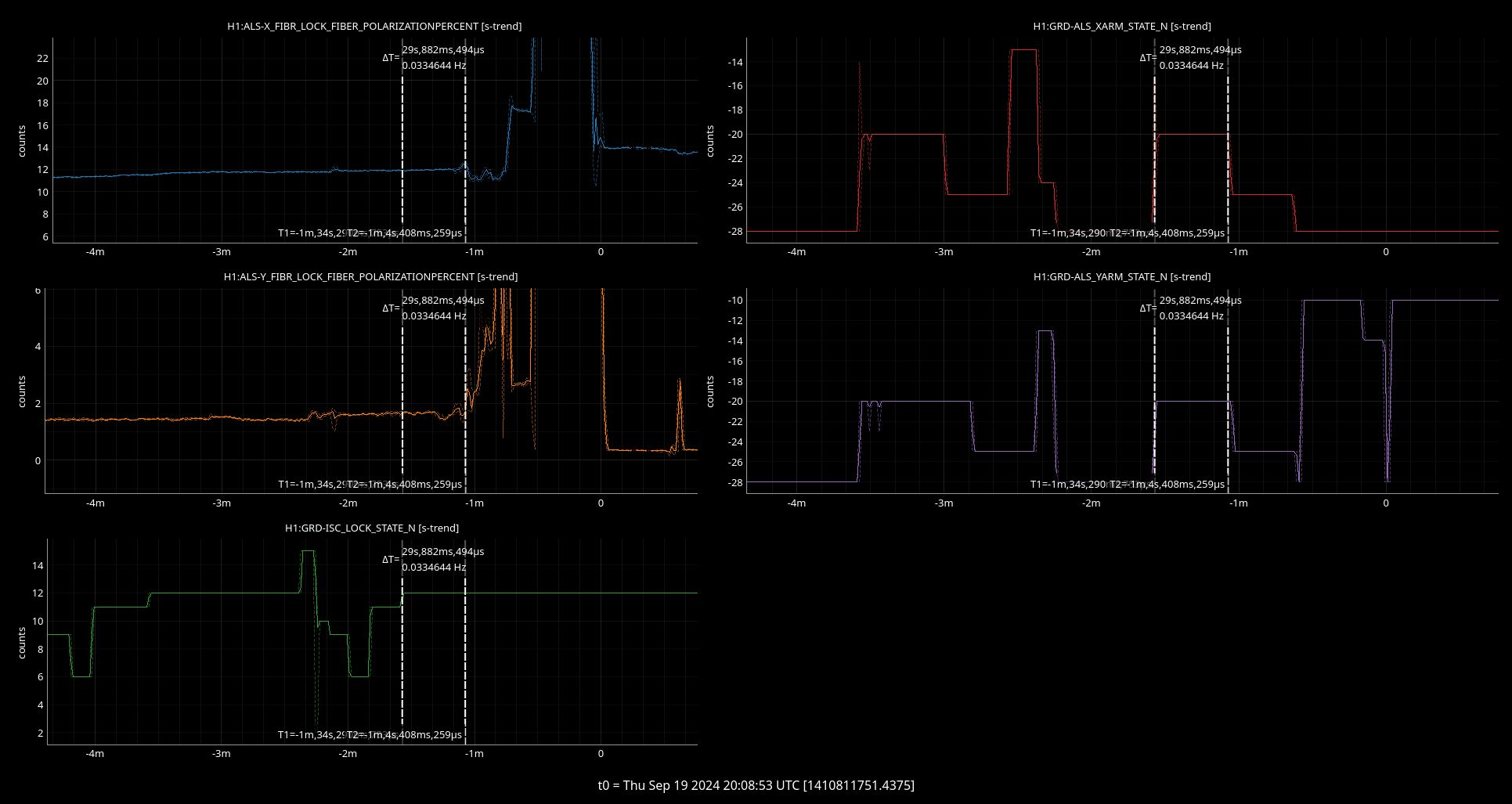
We ran ADS for 3MHz Q to ZM5+6 and the ADF servo to adjust RF3 demod phase based on H1:SQZ-ADF_OMC_TRANS_SQZ_ANG, which moved ZM5 pitch by -19, ZM5 Y by +3urad, ZM6 P by -135 urad, and ZM6 Y by -5 urad, and moved H1:SQZ-CLF_REFL_RF6_PHASE_PHASEDEG by -45 degrees. After this finished we ran SCAN_SQZANG to readjust the squeezing angle (RF6 MHz) to minimize shot noise at 300 Hz, which indicated that the demod phase change we needed to compensate for the alignment shift was actually only 25 degrees. So, thinking about ZM6 P, we see that an alignment would require a 0.2 degree shift in demod phase, and also causes a similar sized error in the squeezing angle read out by the ADF.
After all this, we went back to our best squeezing by running scan alignment and scan sqz angle, then moved ZM6 by -100 urad and re-ran scan sqz angle, we needed to shift the 6MHz demod angle by -16.4 degrees.
The line heights of some of the PCAL lines in the cleaned channel have been much higher than actual at the begining of todays' locks (attachment 1). The relock yesterday didn't have it (attachment 2). Looks like this was potentially fixed a month ago - alog79558, but perhaps the locks from today are too short?
This is most likely caused by a slightly different issue that what was addressed in LHO aLOG 79558. In some instances, the line subtraction TFs are not updating properly at the beginning of lock stretches. I am working on a fix for this.
No obvious cause for the 1410810810 lock loss. The lock lost tool tagged FSS oscillations, which do seem present, but the lock loss was very fast. There was no DARM wiggle as we often see, or movement in the ETMX.
Observing at 2106UTC.
Relocking was interesting. ALS Y had some odd glitches that caused a few lock losses. Tens of minutes later, the polarization of ALS Y and X started to change drastically. This caused the guardian to turn on the controller and adjust it. No idea why the polarization would act like this (screenshot attached). Eventually, after some lock losses at PRMI, everything worked itself out and the IFO made it up. I never touched anything, this was all fully auto without an initial alignment.
Commissioning is complete and we have relocked. Observing at 1923UTC
SQZ ADS dithers are now OFF during observing. See SDFs accepted - the ADS dither gains are set to 0 (so it is off), and the ASC gains and sensing matrix have bene reverted to the previous settings for AS42 ASC.
This should resolve the dithers being accidentally left on the past few days, see Sheila lho80185.
We lost lock during commissioning because of a big (100 cts) PIT step of ZM4, when it's TRAMP = 0.1. That TRAMP being too short was due to a guardian setting bug during SCAN_ALIGNMENT, which is now fixed. We tried the big ZM4 step in an attempt to re-measure the AS42 sensing matrix using ZM4 instead of ZM5, since the ZM5 steps gave very small changes in AS42 WFS with significant P/Y coupling. Measuring the AS42 sensing matrix with ZM4+6 might be worth trying again in the future (especially - check that ZM4 slider TRAMPS are >1 second).
The TRAMPs for ZM4,5,6 slider offsets are all set to 3 seconds now, and that has also been saved in SDF.
ZM5 + ZM6 have had alignment dithers running accidentally in observing since Monday morning, which have now been turned off. (They were on from 9/16/2024 17:40 UTC until 9/19 16:47 UTC). These were small dither lines at 4.1 Hz, 3.5 Hz, 4.5 Hz, and 3 Hz.
BRSX has been running with it's heater almost maxed out at 9V for a while, meaning the hot pad has been sitting at about 50 C for a long time, so Tuesday I reduced the voltage to 7V and made an adjustment to the pico mass adjuster. Changing the heater voltage takes ~1day to settle out, the mass adjustment only took an hour or so to damp down. I adjusted the picomotor using the > button on the middle lower left control keypad on the overview in -1000 step increments. -1000 to engage the yoke, -2000 step adjustment to the mass, +1000 steps to disengage the yoke. This moved the dc position from around 0 to ~-6000. The 2V drop on the heater has now settled out to about +6000, and reduced the hot pad temp to about 40C, and reduced the igloo temp .3C . I think VEA temps trend up as weather cools off outside, higher temps push the dc position negative on this BRS, so I think I will wait a few weeks before making any more adjustments.
Followed instructions in 74681. Last done in 78782, 79988. Saved in /ligo/gitcommon/NoiseBudget/aligoNB/aligoNB/H1/couplings/ and pushed to git.
CHARD_P, CHARD_Y, MICH, PRCL, SRCL screenshots attached. The IFO had been in NLN for 4h15 when these were taken. The AS_A_YAW and PRCL offsets were turned off.
I modified the script used in 78969 to project PRCL noise to DARM through MICH and SRCL, and now added coupling through CHARD P + Y.
There is high coherence between PRCL and CHARD, but these active injections that Camilla did show that the main coupling of PRCL to DARM is not through CHARD.
This script is now in /ligo/gitcommon/NoiseBudget/simplepyNB/PRCL_excitation_projections.py (not actually a git repo)
Sheila, Vicky - we ran the noise budget using these updated couplings from Camilla.
Noise budget with squeezing - pdf and svg (and the quantum sub-budget with squeezing). Plots without unsqueezed DARM here: pdf and svg. Picked a time with high range, and good ~4.8dB squeezing.
Noise budget without squeezing - pdf and svg (and the quantum sub-budget without squeezing).
The remaining sub-budgets are for squeezed DARM: Laser, Jitter, LSC, ASC, Thermal, PUMDAC.
Noise below 25 Hz looks pretty well accounted for: 10-15 Hz ~ ASC (CHARD Y, then CSOFT P, CHARD P). 15-20 Hz ~ LSC (PRCL).
Some comments and caveats for these budget plots:
The code has been pushed to aligoNB repo, commit 95d3a88b. To make these noise budget plots:
Thanks to Erik von Reis for helping us update the aligoNB environment to newer python and scipy (etc) versions. Next to-do: have the budget code use median averaging to be more robust to glitches (which can be done now that the environment has an updated scipy!).
Ran the usual broad band and simulines following the wiki. I ramped the AS_A Y offset to OFF before starting this measurement.
Simulines start:
PDT: 2024-09-19 08:37:18.910765 PDT
UTC: 2024-09-19 15:37:18.910765 UTC
GPS: 1410795456.910765
2024-09-19 15:37:20,007 | INFO | File written out to: /ligo/groups/cal/H1/measurements/DARMOLG_SS/DARMOLG_SS_20240919T1
53719Z.hdf5
2024-09-19 15:37:20,021 | INFO | File written out to: /ligo/groups/cal/H1/measurements/PCALY2DARM_SS/PCALY2DARM_SS_2024
0919T153719Z.hdf5
2024-09-19 15:37:20,035 | INFO | File written out to: /ligo/groups/cal/H1/measurements/SUSETMX_L1_SS/SUSETMX_L1_SS_2024
0919T153719Z.hdf5
2024-09-19 15:37:20,046 | INFO | File written out to: /ligo/groups/cal/H1/measurements/SUSETMX_L2_SS/SUSETMX_L2_SS_2024
0919T153719Z.hdf5
2024-09-19 15:37:20,056 | INFO | File written out to: /ligo/groups/cal/H1/measurements/SUSETMX_L3_SS/SUSETMX_L3_SS_2024
0919T153719Z.hdf5
End:
2024-09-19 16:06:55,132 | INFO | File written out to: /ligo/groups/cal/H1/measurements/DARMOLG_SS/DARMOLG_SS_20240919T1
53719Z.hdf5
2024-09-19 16:06:55,144 | INFO | File written out to: /ligo/groups/cal/H1/measurements/PCALY2DARM_SS/PCALY2DARM_SS_2024
0919T153719Z.hdf5
2024-09-19 16:06:55,155 | INFO | File written out to: /ligo/groups/cal/H1/measurements/SUSETMX_L1_SS/SUSETMX_L1_SS_2024
0919T153719Z.hdf5
2024-09-19 16:06:55,166 | INFO | File written out to: /ligo/groups/cal/H1/measurements/SUSETMX_L2_SS/SUSETMX_L2_SS_2024
0919T153719Z.hdf5
2024-09-19 16:06:55,176 | INFO | File written out to: /ligo/groups/cal/H1/measurements/SUSETMX_L3_SS/SUSETMX_L3_SS_2024
0919T153719Z.hdf5
ICE default IO error handler doing an exit(), pid = 1416632, errno = 32
PDT: 2024-09-19 09:06:55.226746 PDT
UTC: 2024-09-19 16:06:55.226746 UTC
GPS: 1410797233.226746
Thu Sep 19 08:10:32 2024 INFO: Fill completed in 10min 28secs
Jordan confirmed a good fill curbside.
TITLE: 09/19 Day Shift: 1430-2330 UTC (0730-1630 PST), all times posted in UTC
STATE of H1: Observing at 154Mpc
OUTGOING OPERATOR: Ibrahim
CURRENT ENVIRONMENT:
SEI_ENV state: CALM
Wind: 4mph Gusts, 3mph 3min avg
Primary useism: 0.01 μm/s
Secondary useism: 0.10 μm/s
QUICK SUMMARY: Locked for 2hr41min. Calm environment. Planned calibration and commissioning today from 830-12 PT
-Mattia, Sheila
We have written a python script to compute the full matrix of power spectral densities and cross-power spectral densities between a given channel, i.e., DARM, and a set of auxiliary channels. The code can be find at this repository https://git.ligo.org/mattia.emma/cross_psd which includes a README file describing how to run it.
The main arguments the user has to pass are the start time (in GPS time) and length of the data to retrieve from gwpy, a list of channel names and the starting frequency for the strain plots.
The code creates five different types of plots using the coherence and cross-power spectral density matrix. The final result of the code is a coefficient for each frequency value expressing the algebraic sum of the contributions of all the auxiliary channels to DARM considering the cross-power spectral density terms. It also computes the coherence between the single auxiliary channels and the DARM channel, which are the diagonal terms in the cross-power spectral density matrix.
The five kinds of plots are:
All of these plots can also be created using as a main channel any auxiliary channel instead of DARM, e.g., if one would like to study the correlation between auxiliary channels. Each plot name also includes the start and end GPS time of the data used for them.
Comments are welcome. As a next step we would like to implement interactive plots to allow the user to include/exclude lines from the plots.
We have now added a code and instructions to the GitLab to obtain an interactive plot on one's local server.
The webpage displays two plots as shown in the attached screenshots (third and fourth image) and allows the user to select which lines to show through a checklist. It is possible to save a screenshot of each plot, zoom-in and out, and hover over the data.
The two included plots are (1) a plot of the normalized residuals between the DARM noise and the cumulative strain contribution of the auxiliary channels , and (2) "Plot 2" from the above aLog, showing the cumulative contribution of the selected channels to the DARM noise.
The code is publicly accessible on GitLab at Cross_psd .
J. Kissel, O. Patane A follow-up from yesterday's work on installing the infrastructure of the upgrades to the ETM and TMS watchdog systems, in this aLOG I cover with what I've filled out the infrastructure in order to obtain the calibrated BLRMS that forms the trigger signal for the user watchdog. Remember, any sensible BLRMS system should (1) Take a signal, and filter with with a (frequency) band-limiting filter, then (2) Take the square, then the average, then square root, i.e. the RMS, then (3) Low-pass the RMS signal, since only the "DC" portion of the RMS has interesting frequency content. As a bonus, if your signal is not calibrated, then you can add (0) Take the input to the band limiting filter, and calibrate it (and through the power of linear algebra, it doesn't really matter whether you band-limit first and *then* calibrate) This screenshot shows the watchdog overview screen conveying this BLRMS system. Here're the details of the BANDLIM and RMSLP filters for each of the above steps: (0) H1:SUS-ETMX_??_WD_OSEMAC_BANDLIM_?? FM6 ("10:0.4") and FM10 ("to_um") are exact copies of the calibration filters that are, and have "always been" in the OSEMINF banks. These are highlighted in the first attachment in yellow. FM6 :: ("10:0.4") :: zpk([10],[0.4],1,"n") :: inverting the frequency response of the OSEM satellite amp frequency response FM10 :: ("to_um") :: zpk([],[],0.0233333,"n") :: converting [ADC counts] into [um] assuming an ideal OSEM which has a response of 95 [uA / mm], differentially readout with 242 kOhm transimpednance and digitized with a 2^16 / 40 [ct / V] ADC. In addition, I also copied over the GAIN from the OSEMINF banks and copied these over as well such that each OSEM trigger signal remains "normalized" to an ideal 95 [uA / mm] OSEM. These are highlighted in dark green in the first attachment. (1) H1:SUS-ETMX_??_WD_OSEMAC_BANDLIM_?? FM1 :: ("acBandLim") :: zpk([0;8192;-8192],[0.1;9.99999;9.99999],10.1002,"n") :: 0.1 to 10 Hz band-pass (2) This is a major part of the upgrade -- the front-end code that does the RMS was changed from the nonsense "cdsRms" block (see LHO:1265) to a "cdsTrueRMS" block (see LHO:19658) (3) H1:SUS-ETMX_??_WD_OSEMAC_RMSLP_?? FM1 :: ("10secLP") :: butter("LowPass",4,0.1) :: 4th order butterworth filter with a corner frequency at 0.1 Hz, i.e. a 10 second Low Pass. This is highlighted in magneta in the second attachment. These are direct copies from other newer suspension models that had this infrastructure in place. I've committed the filter files to the userapps repo, /opt/rtcds/userapps/release/sus/h1/filterfiles/ H1SUSETMX.txt H1SUSETMY.txt H1SUSETMXPI.txt H1SUSETMYPI.txt H1SUSTMSX.txt H1SUSTMSY.txt are all committed as of rev 27217. All of these settings were captured in each model's safe.snap. I've not yet accepted them in the OBSERVE.snaps.
Here's a handy script that demos using the python bindings to foton in order to easily populate simple filters from a python script. I've only used this from the control room workstations, whose environment has been already built up for me, so I can't claim any knowledge of details about what packages this script needs. But, if you have the base cds conda environment this "should work."