In preparation for WP 12079, I prepared ESDOUTF (L3) and COILOUTF (L1, L2) filters to make up the calibration difference between 18-bit and the new 32-bit DACs. This is similar to what was done in LHO:64274 to adjust from 18-bit DACs to 20-bit DACs. Similarly, I placed new '32bitDAC' gains in CALCS-ETMX. In CAL-CS, the new gains are intended to replace the gains of '4'. I have not yet loaded the filter coefficients, but they have been saved in the filter files.
FAMIS27776
For the most part the chillers lines look good, nothing new showed up. To redocument a few items with pictures:
Both sock filters were replaced and gunk found in the water reservoirs.
I noticed the other month that the sock filters were starting to look green. I was hesitant to replace them while we were observing, so I waited for a maintenance day that I was available. Well, we should have replaced them sooner. The TCSY sock had gunk on the inside of the sock and the outside (attachment 9), TCSX was similar but not as bad (attachment 10). The big issue is that there was chunks of gunk suspended in the reservoirs (TCSY res. & TCSX). I'm not sure if this gunk is making it around our sock filters* or if it's just working its way through. The latter possible since I saw some gunk on the outside of the TCSY sock.
It looks like the last time that we replaced these filters was Aug 2023 (alog72253), so we should set up a famis to remind us to do this sooner. The manual recommends replacing them every 3-4 months or so. While I don't recall ever replacing them that frequently in the past, perhaps it's time to start.
*Years ago we decided that not pushing the sock's gasket fully into its seat and instead angling it toward the flow of the water, but allowing an air gap on the far side, gave us more accurate reservoir level readings and still had almost all of the water go into the sock.
Tue Sep 10 08:12:19 2024 INFO: Fill completed in 12min 15secs
Gerardo confirmed a good fill curbside.
TITLE: 09/10 Day Shift: 1430-2330 UTC (0730-1630 PST), all times posted in UTC
STATE of H1: Calibration
OUTGOING OPERATOR: TJ
CURRENT ENVIRONMENT:
SEI_ENV state: CALM
Wind: 3mph Gusts, 1mph 3min avg
Primary useism: 0.01 μm/s
Secondary useism: 0.08 μm/s
QUICK SUMMARY:
IFO is in NLN and CALIBRATION for automatic PEM Injections and In-Lock SUS Charge measurements, since we're locked (and have been for near 15 hours!)
Planning to head into Planned Tuesday Maintenance once those are done running, which should be at 8AM.
As per WP 12069 I will be switching to the backup CDS router. After discussion with the operator we will do this at 8am localtime. This will temporarily break the link between the CDS network and the rest of the world. It will not interrupt the IFO or control room work that stays within the CDS network. The procedure to do this switchover for the current setup is documented in LIGO-T2300212.
This test is done. I was a little nicer in my procedure than the DCC document. I issued a poweroff command to the router instead of hitting the power button. The router appears to be working. I will leave it in this configuration.
The temporary removal of offsite access has exposed a bug in my locklossalert code. After it lost connection to Twilio, it stopped updating even after the network was restored. FRS has been opened.
I restarted the locklossalert systemd service on cdslogin. I also restarted the alarms service to ensure it was able to send texts.
Workstations were updated and rebooted. This was an OS packages updated. Conda packages were not updated.
TITLE: 09/10 Eve Shift: 2330-0500 UTC (1630-2200 PST), all times posted in UTC
STATE of H1: Observing at 149Mpc
INCOMING OPERATOR: TJ
SHIFT SUMMARY: We've been locked for just over 5 hours, the range has been just under 160, and the wind has calmed back down.
23:54 UTC Observing
TITLE: 09/09 Day Shift: 1430-2330 UTC (0730-1630 PST), all times posted in UTC
STATE of H1: Lock Acquisition
INCOMING OPERATOR: Ryan C
SHIFT SUMMARY: Currently relocking and at ENGAGE_ASC_FOR_FULL_IFO. One lockloss today (79991) but not much to report. Relocking is taking a while because of changes in the ISC_LOCK code and not because of IFO issues.
LOG:
14:30UTC Observing and Locked for 4:50 hours
15:31 Out of Observing for Commissioning
18:31 Back into Observing
20:01 Out of Observing due to SQZer unlock
20:12 Lockloss
21:45 Lockloss from LASER_NOISE_SUPPRESSION (probably user error/people on floor)
22:41 Lockloss from ADS_TO_CAMERAS
Start Time | System | Name | Location | Lazer_Haz | Task | Time End |
---|---|---|---|---|---|---|
15:05 | FAC | Karen | VacPrep, OptLab | n | Tech clean | 15:20 |
15:26 | FAC | Karen | MY | n | Dumping garbage | 17:10 |
15:29 | FAC | AC company | VPW | n | New AC unit install | 19:40 |
16:01 | FAC | Kim | MX | n | Tech clean | 18:07 |
17:12 | FAC | Mitchell | EX | n | Grabbing dust monitor pump | 18:39 |
17:51 | Betsy | CER, OptLab | n | Grabbing stuff and looking for sand | 17:58 | |
19:07 | FAC | Tyler | OptLab | n | Looking at sandy flow bench | 19:13 |
20:50 | SQZ | Vicky, Naoki | LVEA | YES | ISS alignment on SQZT0 | 21:50 |
TITLE: 09/09 Eve Shift: 2330-0500 UTC (1630-2200 PST), all times posted in UTC
STATE of H1: Lock Acquisition
OUTGOING OPERATOR: Oli
CURRENT ENVIRONMENT:
SEI_ENV state: CALM
Wind: 23mph Gusts, 16mph 3min avg
Primary useism: 0.03 μm/s
Secondary useism: 0.06 μm/s
QUICK SUMMARY:
Back to observing at 23:54 UTC
Vicky, Naoki
We aligned pump AOM and fiber. This time, we aligned AOM from front panel without opening the back panel. So this work can be done with local laser harzard.
We set ISS drivepoint at 0V and measured the AOM throughput. The throughput was 40 mW/62 mW = 65%. We aligned AOM to maximize the throughput and got 59.5 mW/62 mW = 96% throughput.
Then we set ISS drivepoint at 5V and aligned AOM to maximize the 1st order beam. The 1st order beam increased from 3.7mW to 9.1mW. However, when we set the ISS drivepoint at 0V, the AOM output was only 40.5mW. This is already reported in 78519. We aligned AOM to maximize the throughput and got 58.7mW of AOM output.
We repeated this alignment several times as follows.
1st order@5V ISS: 15.8 mW, 0th order@0V ISS: 48 mW, 60mW after alignment
1st order@5V ISS: 16.3 mW, 0th order@0V ISS: 52.4 mW, 56mW after alignment
1st order@5V ISS: 15.3 mW, 0th order@0V ISS: 53 mW
We were getting better AOM throughput at 0V ISS while maitaining the reasonable 1st order beam at 5V ISS. We could improve the alignment more, but we stopped here due to time limitation.
Finally we aligned the pump fiber.
FAMIS 31050
The PMC reflected increase/transmitted decrease in power trend is ongoing. Not much else to note on this week's trends.
A while ago Oli found that some earthquakes cause IMC splitmon saturations, possibly causing locklosses. I asked Daniel this with respect to the tidal system to see if we could improve the offloading some. After some digging we found that some of the gains in the IMC get lowered to -32db at high power, greatly reducing the effective range of the IMC SPLITMON. He and Sheila decided that the best place to recover this gain was during the LASER_NOISE_SUPPRESSION state (575) so Sheila added some code to that state to redistribute some the gain (lines 5778 -5788):
self.gain_increase_counter = 0
if self.counter ==5 and self.timer['wait']:
if self.gain_increase_counter <7: #icrease the imc fast gain by this many dB
#redistribute gain in IMC servo so that we don't saturate splitmon in earth quakes, JW DS SED
ezca['IMC-REFL_SERVO_IN1GAIN'] -= 1
ezca['IMC-REFL_SERVO_IN2GAIN'] -= 1
ezca['IMC-REFL_SERVO_FASTGAIN'] += 1
time.sleep(0.1)
self.gain_increase_counter +=1
else:
self.counter +=1
We tried running this, but an error in the code broke the lock. That's fixed now, the lines are commented out in ISC_LOCK and we'll try again in some other day.
This caused 2 locklosses, so it took a little digging to figure out what is happening. The idea is to increase H1:IMC-REFL_SERVO_FASTGAIN, to compensate for reducing H1:IMC-REFL_SERVO_IN1GAIN and H1:IMC-REFL_SERVO_IN2GAIN, all analog gains used in IMC/tidal controls. It turns out there is a decorator used in almost every state of IMC_LOCK that sets H1:IMC-REFL_SERVO_IN1GAIN to some value, so when ISC_LOCK changes all 3 of these gains, IMC_LOCK was coming in after and resetting FASTGAIN. This is shown in the attached trend,on the middle plot the IN1 and IN2 gains step down like they are supposed to, but the FASTGAIN does a sawtooth caused by two guardians controlling this gain. The decorator is called IMC_power_adjust_func() in ISC_library.py and is called as @ISC_library.IMC_power_adjust in IMC_LOCK. The decorator just looks at the value of the FASTGAIN, Daniel suggests that it would be best for this decorator to look at all of the gains and do this a little smarter. I think RyanS will look into this, but looks like redistributing gain in the IMC is not straightforward.
tagging this with SPI. This would be good to compare against. The SPI should reduce HAM2-3 motion and reduce IMC length changes coming directly from ground motion. If IMC drive is to match the arm length changes then it won't help. (unless we do some feedforward of the IMC control to the ISIs?)
VACSTAT, the vacuum glitch detection system, is now online after a soft rollout. This is a stand-alone EPICS IOC which monitors vacuum gauge pressures and reports if it has detected a vacuum pressure glitch.
Its overview medm can be launched from the sitemap VE pull down, or from the CDS Overview vacuum section.
The attached image shows the VACSTAT Overview MEDM, the system details MEDM and a trend plot MEDM for one of the pressure gauges.
For each pressure gauge, the system maintains lookback FIFOs of the pressure trends. Currently the system is looking back 60, 300 and 600 seconds. Every 10 seconds, the slopes of the data are calculated using a linear regression algorithm. If the absolute value of a slope exceeds its trip value, a glitch detection is raised.
In addition, the total change in pressure over each trend is calculated (Pdelta = Pmax - Pmin). If the delta pressure exceeds a trip value, a glitch detection is raised.
The trend plots have three rows, one for each of the lookback time. The left column is a live plot which continuously streams. The right column latches if a glitch is detected, stopping when the glitch is at the half-way mark.
If a glitch is detected, cell phone alarms are sent to the vacuum team. In addtion, the VACSTAT block on the CDS Overview MEDM will go RED.
All parameters of the system are defined by a configuration yaml file. I'm in the process of writing the user guide.
prod.yaml currently in use in production:
---
ifo: H1
glitch_monitor:
lookback_times: [60, 300, 600]
proc_period_secs: 10
vacuum_gauges:
default:
glitch_press_rate: [1.0e-10, 1.0e-10, 1.0e-10]
glitch_delta_press: [1.0e-08, 1.0e-08, 1.0e-08]
valid_value_min: 1.0e-10
valid_value_max: 1.0e-04
H0:VAC-LY_X0_PT100B_PRESS_TORR:
description: "Corner Station HAM1"
H0:VAC-LY_Y1_PT120B_PRESS_TORR:
description: "Corner Station BSC2"
H0:VAC-LX_Y8_PT132_MOD2_PRESS_TORR:
description: "Corner Station BSC3"
H0:VAC-LX_Y0_PT110_MOD1_PRESS_TORR:
description: "Corner Station HAM6"
H0:VAC-LY_Y3_PT114B_PRESS_TORR:
description: "Corner Station CP1"
H0:VAC-LX_X3_PT134B_PRESS_TORR:
description: "Corner Station CP2"
H0:VAC-LY_Y4_PT124B_PRESS_TORR:
description: "Corner Station Y-Arm"
H0:VAC-LX_X4_PT144B_PRESS_TORR:
description: "Corner Station X-Arm"
H0:VAC-MY_Y1_PT243B_PRESS_TORR:
description: "Mid-Y Y1 Beam Tube"
H0:VAC-MY_Y5_PT246B_PRESS_TORR:
description: "Mid-Y Y2 Beam Tube"
H0:VAC-EY_Y1_PT423B_PRESS_TORR:
description: "End-Y Beam Tube"
H0:VAC-EY_Y3_PT410B_PRESS_TORR:
description: "End-Y BSC10"
H0:VAC-MX_X1_PT343B_PRESS_TORR:
description: "Mid-X X1 Beam Tube"
H0:VAC-MX_X5_PT346B_PRESS_TORR:
description: "Mid-X X2 Beam Tube"
H0:VAC-EX_X1_PT523B_PRESS_TORR:
description: "End-X Beam Tube"
H0:VAC-EX_X3_PT510B_PRESS_TORR:
description: "End-X BSC9"
[Elenna, Gabriele]
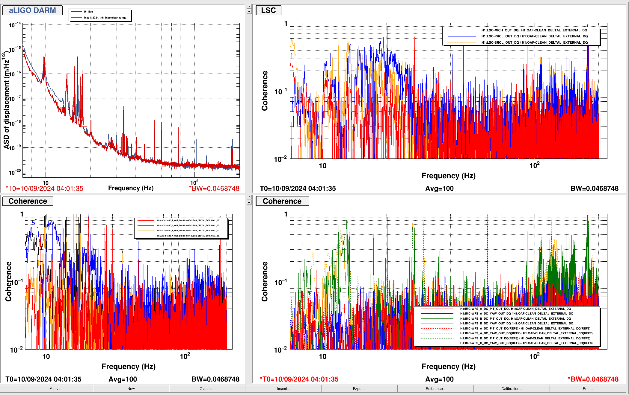
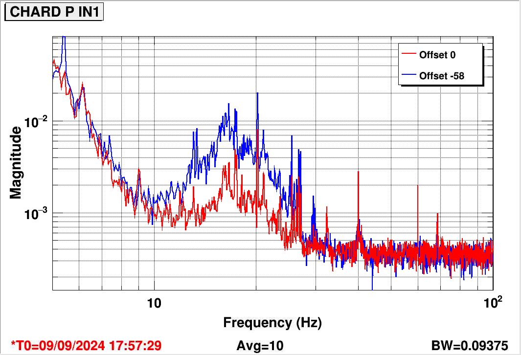
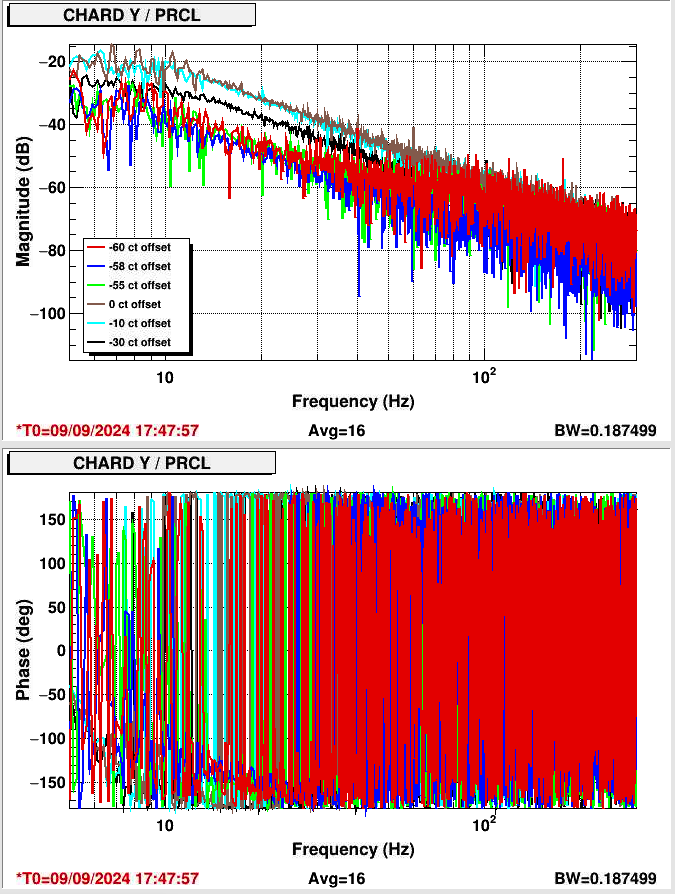
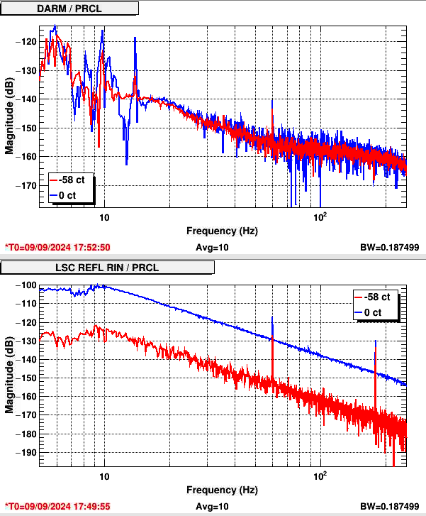
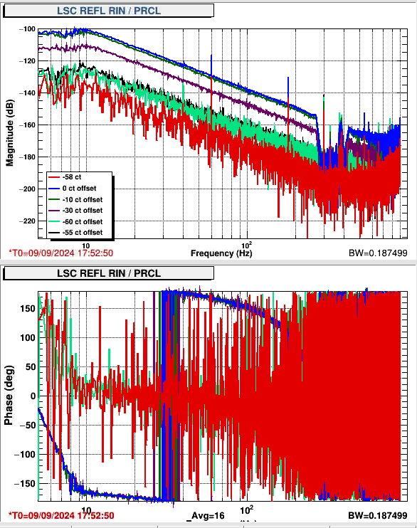
I did another test of the PRCL offset today, mirroring previous tests (76814). The motivation for this test is first the large coherence of DARM with LSC REFL RIN, indicating that we are locked with some offset in PRCL. Next, there is large coherence of PRCL and CHARD Y to DARM, and previous tests have shown some PRCL is coupling through CHARD Y, and that coupling can be reduced by adding a digital offset to PRCL, which counteracts whatever locking offset is present in PRCL.
Once again, a PRCL offset is shown to reduce PRCL/REFL RIN coupling, and PRCL to CHARD Y coupling. The minimum occurs with an offset of about -58 (compare to April's best offset of -62). This coupling indicates an offset somewhere between 25 pm and 50 pm (quoting Gabriele 76810). The digital offset reduces REFL RIN/PRCL coupling by 40 dB. PRCL and LSC REFL RIN coupling plot
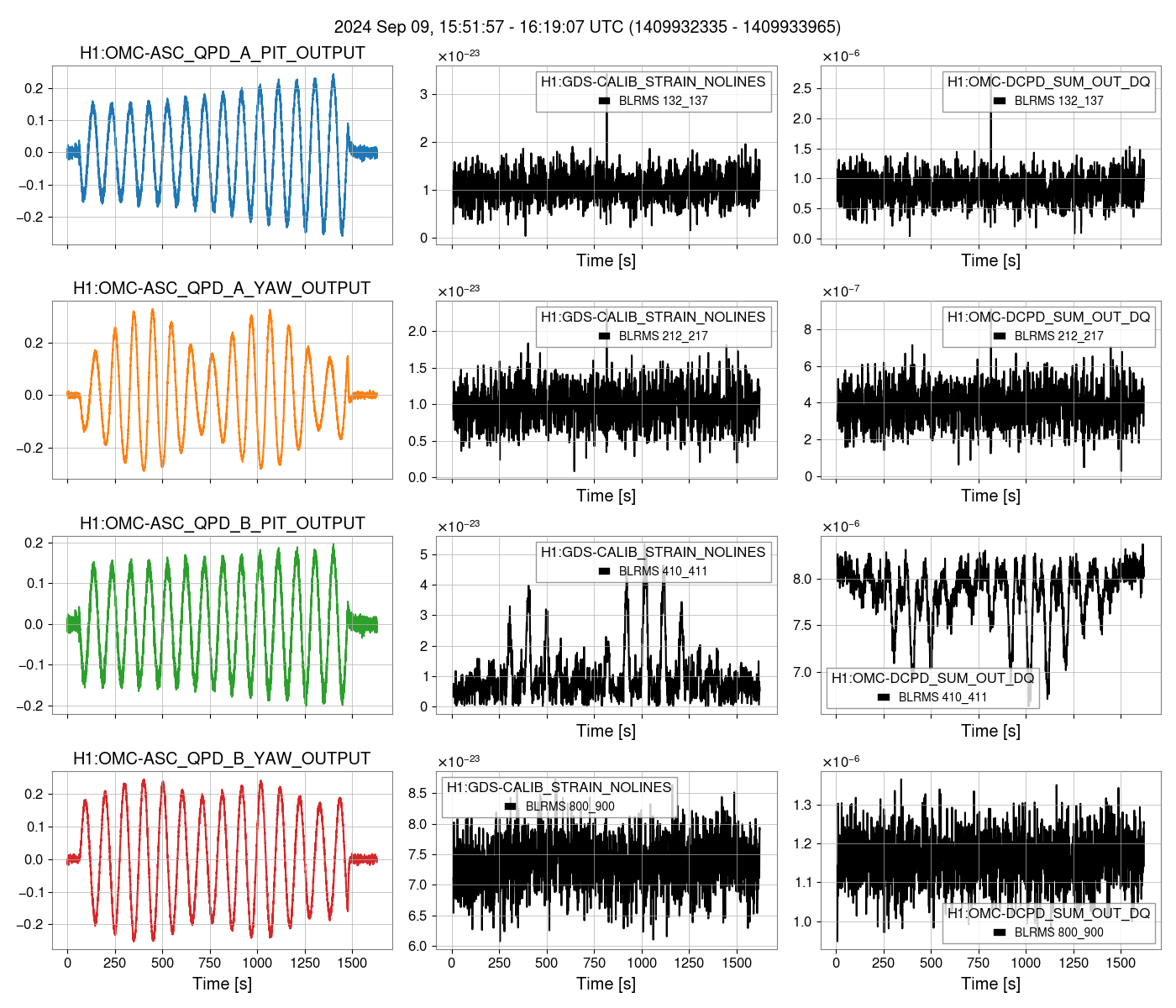
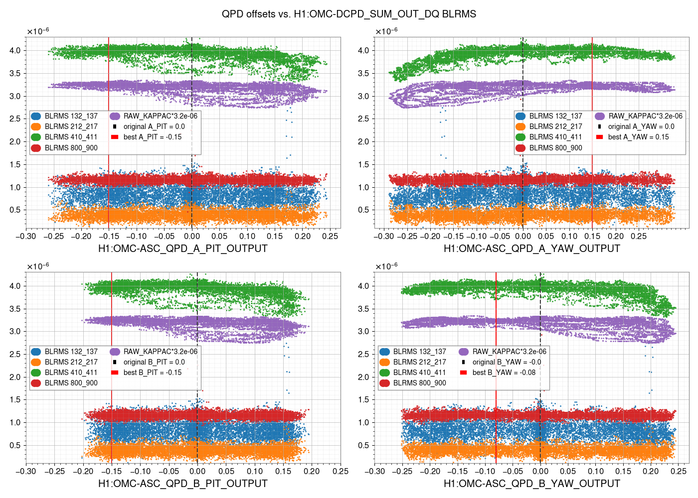
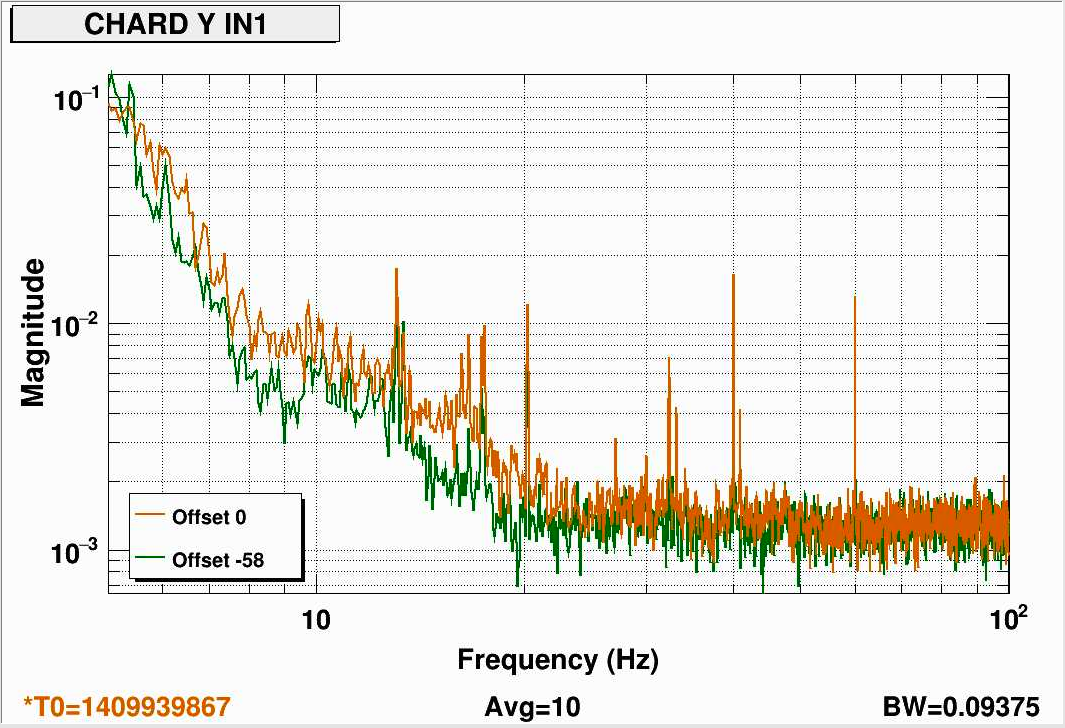
The offset reduces the noise in CHARD Y by reducing the PRCL coupling by a factor of 10. PRCL and CHARD Y coupling plot, and noise reduction in CHARD Y, CHARD Y noise
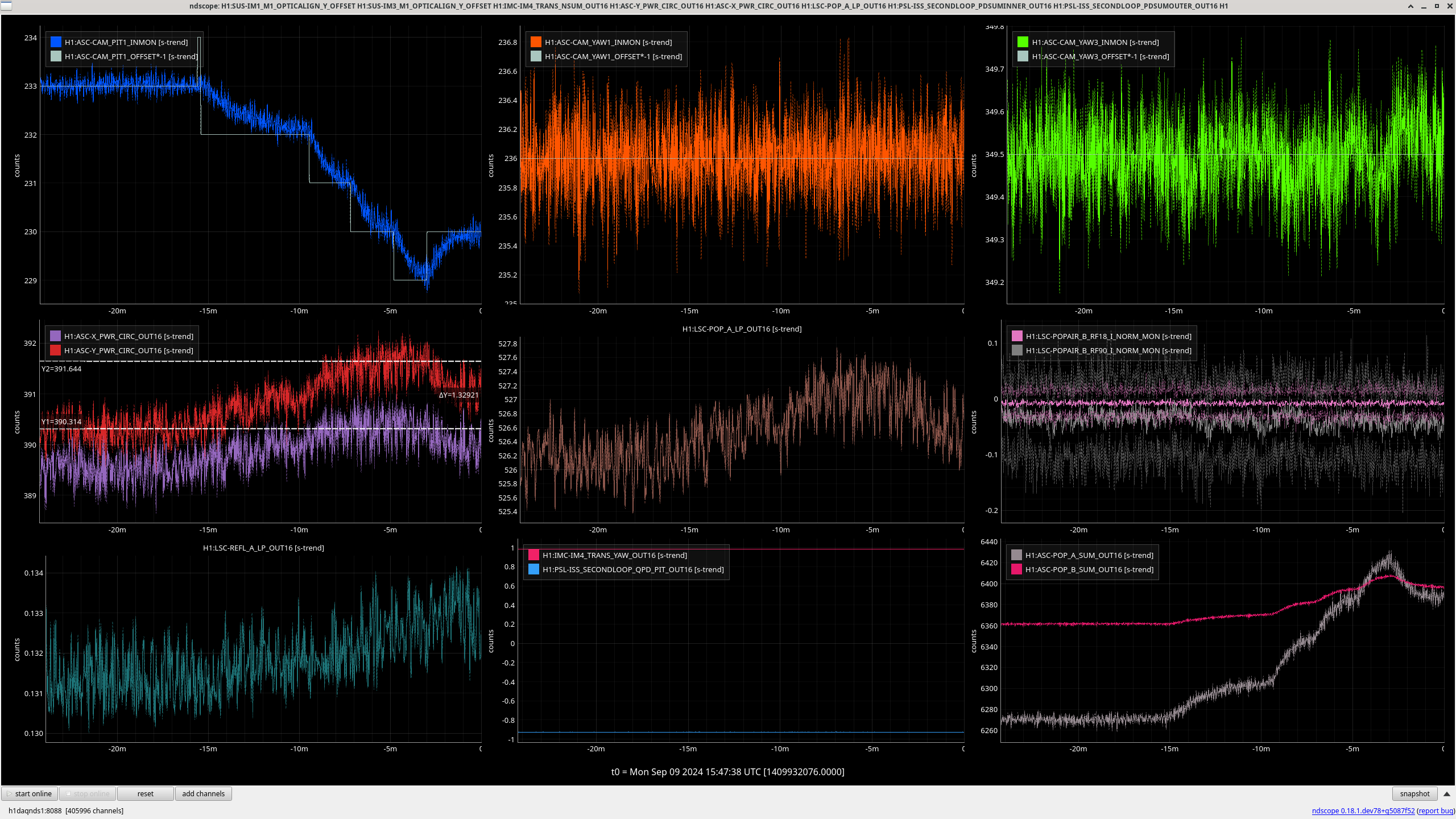
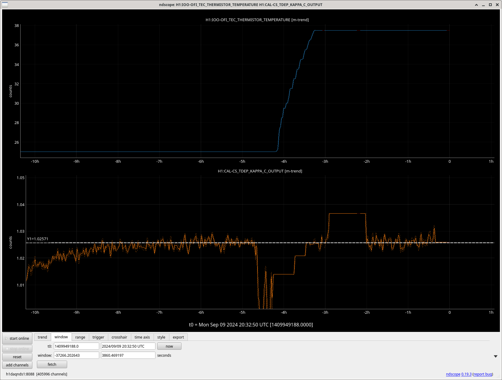
The PRCL to CHARD P coupling does not change, PRCL and CHARD P coupling plot (I was lazy and did not properly label this plot, but each trace is a different offset count similar to the other plots). However, the offset worsens the noise in CHARD P, because the offset effectively changes the amount of HAM1 noise coupling into CHARD P, CHARD P noise. We only checked CHARD P, but it likely changes the noise in INP1 P and PRC2 P as well. With this PRCL offset, I ran a HAM1 FF off time, so we could get data to retune the feedforward. (start: 1409940778, stop: 1409941096).
I think that with this PRCL offset, and with an updated feedforward, we will see some improvement in the low frequency noise. The last time we did this test, we did not check the effect on the feedforward, and this is possibly why the sensitivity did not get better, even though we are seeing the exact same reduction in CHARD Y noise as before.
Overall, we can convince ourselves that this result makes sense because the offset is changing the amount of 00 mode present at the REFL WFS.
We have made no changes yet, but I will fit new feedforward so that we can retest this offset + new HAM1 FF at the next commissioning time.
Overall, the PRCL coupling to DARM did not change much with this offset, which contradicts the idea that most of the PRCL coupling to DARM is occuring through CHARD Y.
I have fit new HAM1 FF filters that can be used when the PRCL offset is engaged. I fit new filters for INP1 P, PRC2 P, and CHARD P. There is very little to subtract for the DC1 and DC2 loops, so I recommend those FFs are turned off when the PRCL offset is engaged. All the new filters are saved in FM10 of the filter banks, and are labeled "PRCL_offset".
TJ, Vicky, Naoki, Sheila
Since the vent we haven't fully checked some of the usual offsets and settings that we might need to adjust, I started with some of them this morning.
I started with stepping the BS camera pitch offset, which I'd started in 79663 but wasn't able to finish at that time because of a lockloss. We gained a little more than 1 kW of circulating power in the arms by adjusting the offset from 233 to 230, see first attachment, this has been added and loaded in lscparams. The improvement on POP A + B may be because of an alignment shift, we are probably clipping on both of those.
Went to no squeezing and ran OMC alingment offset scan: went to no squeezing and copied Jennie's dtt template from 78616. This scan saturated the OMC pitch actuator, so I reduced the OMC ANG Y amplitude from 3 to 1 and restarted the scan at 15:53:07-16:16:29 UTC. TJ and I noticed that the strange flashing behavoir of the OMC camera was coming and going while this scan was happening.
Following up on 79719 I used the template sheila.dwyer/OMC/OMC_fringe_wrapping.xml and reduced the amplitude to 600 as Naoki did to adjust the OFI temperature. We found that the fringe wrapping shelf amplitude was reduced by increasing the temperature, we went up to 37.5C and the amplitude of the shelf dropped by a factor 3 (second screenshot attached). We didn't go hotter than this because we weren't sure how hot we would want to operate. This change in OFI temperature doesn't seem to have changed the optical gain, shown in the 3rd attachment. (template in sheila.dwyer/OMC/OMC_fringe_wrapping_after_OFI_repair.xml, ref 38 25C, ref 39 28.5C, 40 29.5C, ref 41 30.5, ref 42 31.5C, ref 42 31.5C, ref 43 32.5C, ref 45 34.5C, ref 46 35.5C, ref 47 36.5C, ref 48 37.5C. )
Vicky, Naoki and I started some alignment scans for 4 squeezer DOF (ZM5+6 P+Y) with different frequencies (similar to the OMC offsets), at 17:10 UTC- 17:34:20 UTC. (We continued OFI temperature adjustments while this was happening).
Analyzing the OMC alignment offset scan, adapting Gabriele's and Jennie W's codes from lho78616.
Script here lives in /opt/rtcds/userapps/release/omc/h1/scripts/OMC_alignment_dither_check_qpd_offsets.* Saved as both a script and as a jupyter notebook.
If running as a script, then the gps start & stop times around turning on/off the dithers can be input manually (lines 44-45), or on the command line, for example:
There are three main plot outputs:
Current offsets are all 0. Based on today's dithers, could try the following offsets:
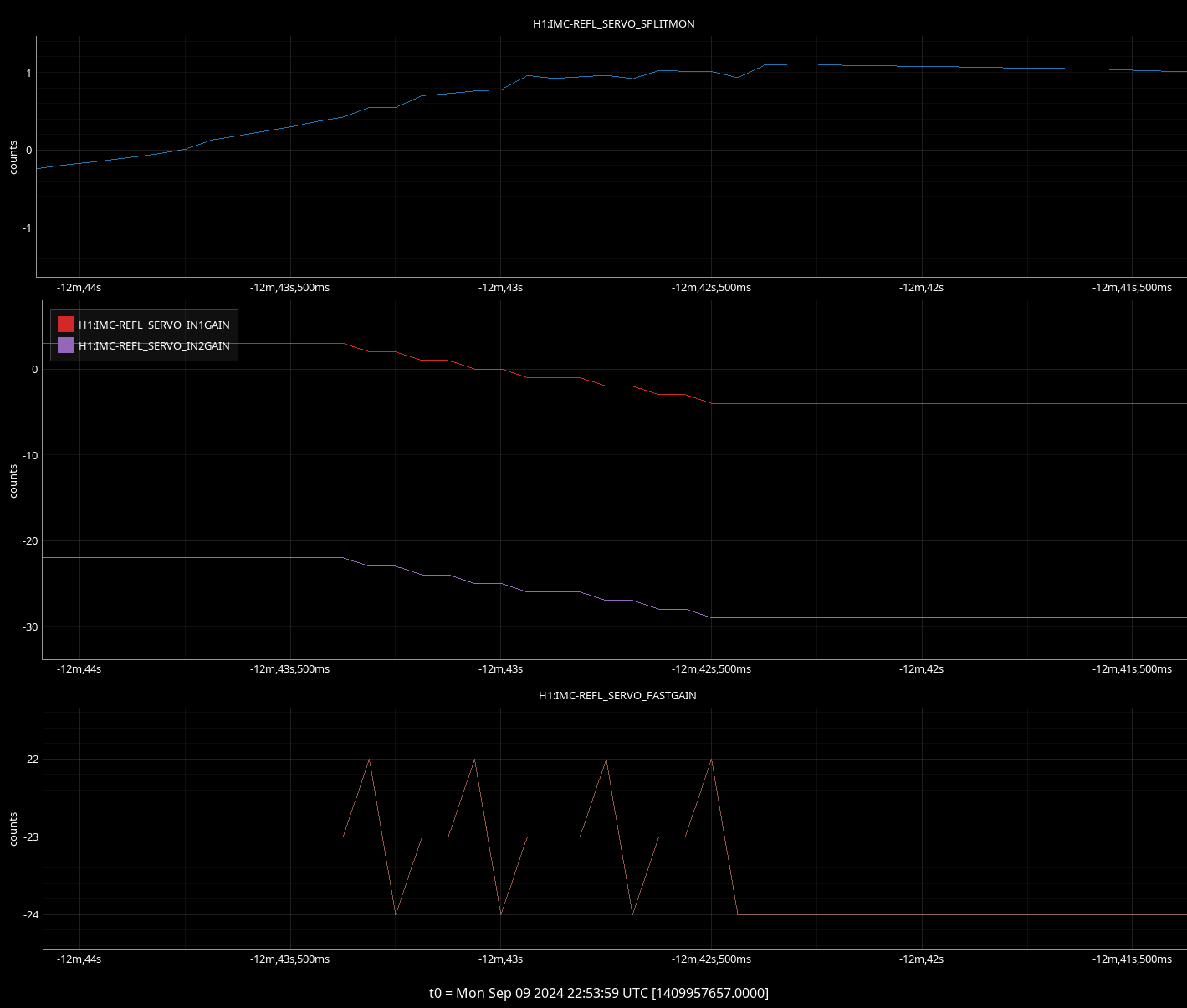
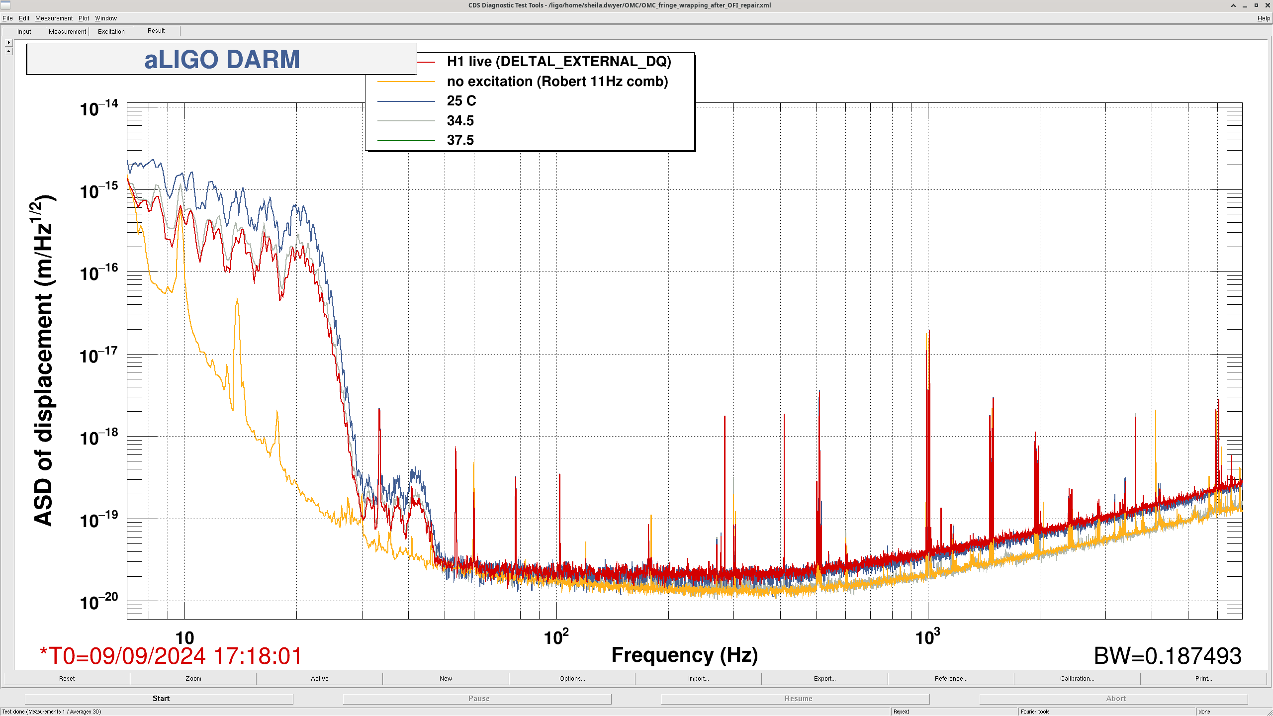
I loaded the filters earlier today, so they should be ready to go whenever we start using these new LIGODACs in-loop.