While testing out new SEI/ISI/HPI guardian code on ITMY this morning (to be logged separately later), Fabrice and I encountered what may be a bug in the watchdog code associated with the T240s in stage 1.
We had applied a large pitch offset on ITMY HPI, and were attempting to restore the system to full isolation. The large pitch offset rang up the T240, causing it to saturate (expected). The new T240 monitor (H1:ISI-ITMY_ST1_T240_MONITOR_OUT) kicked in, and guardian waited for the T240 monitor to clear before it attempted to start isolating stage 1. As soon as the T240 monitor cleared, guardian started to enage the isolation loops and ramp up the gains:
20140514_17:27:05.582 ISI_ITMY_ST1 [WAIT_FOR_T240_SETTLE] 20140514_17:37:28.138 ISI_ITMY_ST1 transitioning state: WAIT_FOR_T240_SETTLE->ENGAGE_ISO_FILTERS_HIGH_RX_RY 20140514_17:37:28.139 ISI_ITMY_ST1 calculating path: ENGAGE_ISO_FILTERS_HIGH_RX_RY->HIGH_ISOLATED 20140514_17:37:28.139 ISI_ITMY_ST1 new target: RAMP_ISO_FILTERS_UP_HIGH_RX_RY 20140514_17:37:28.139 ISI_ITMY_ST1 executing state: ENGAGE_ISO_FILTERS_HIGH_RX_RY 20140514_17:37:28.139 ISI_ITMY_ST1 [ENGAGE_ISO_FILTERS_HIGH_RX_RY] 20140514_17:37:28.204 ISI_ITMY_ST1 [ENGAGE_ISO_FILTERS_HIGH_RX_RY.run] ezca: H1:ISI-ITMY_ST1_ISO_RX_SW1S => 21508 20140514_17:37:28.330 ISI_ITMY_ST1 [ENGAGE_ISO_FILTERS_HIGH_RX_RY.run] ezca: H1:ISI-ITMY_ST1_ISO_RX_SW2S => 1537 20140514_17:37:28.455 ISI_ITMY_ST1 [ENGAGE_ISO_FILTERS_HIGH_RX_RY.run] ezca: H1:ISI-ITMY_ST1_ISO_RX => ONLY ON: INPUT, OUTPUT, DECIMATE, FM4, FM5, FM6, FM7 20140514_17:37:28.456 ISI_ITMY_ST1 [ENGAGE_ISO_FILTERS_HIGH_RX_RY.run] ezca: H1:ISI-ITMY_ST1_ISO_RY_SW1S => 21508 20140514_17:37:28.582 ISI_ITMY_ST1 [ENGAGE_ISO_FILTERS_HIGH_RX_RY.run] ezca: H1:ISI-ITMY_ST1_ISO_RY_SW2S => 1537 20140514_17:37:28.708 ISI_ITMY_ST1 [ENGAGE_ISO_FILTERS_HIGH_RX_RY.run] ezca: H1:ISI-ITMY_ST1_ISO_RY => ONLY ON: INPUT, OUTPUT, DECIMATE, FM4, FM5, FM6, FM7 20140514_17:37:28.889 ISI_ITMY_ST1 transitioning state: ENGAGE_ISO_FILTERS_HIGH_RX_RY->RAMP_ISO_FILTERS_UP_HIGH_RX_RY 20140514_17:37:28.890 ISI_ITMY_ST1 calculating path: RAMP_ISO_FILTERS_UP_HIGH_RX_RY->HIGH_ISOLATED 20140514_17:37:28.890 ISI_ITMY_ST1 new target: ENGAGE_ISO_BOOST_HIGH_RX_RY 20140514_17:37:28.890 ISI_ITMY_ST1 executing state: RAMP_ISO_FILTERS_UP_HIGH_RX_RY 20140514_17:37:28.891 ISI_ITMY_ST1 [RAMP_ISO_FILTERS_UP_HIGH_RX_RY] 20140514_17:37:28.954 ISI_ITMY_ST1 [RAMP_ISO_FILTERS_UP_HIGH_RX_RY.run] ezca: H1:ISI-ITMY_ST1_ISO_RX_TRAMP => 10.000 20140514_17:37:28.954 ISI_ITMY_ST1 [RAMP_ISO_FILTERS_UP_HIGH_RX_RY.run] ezca: H1:ISI-ITMY_ST1_ISO_RX_GAIN => 0.010 20140514_17:37:28.955 ISI_ITMY_ST1 [RAMP_ISO_FILTERS_UP_HIGH_RX_RY.run] ezca: H1:ISI-ITMY_ST1_ISO_RY_TRAMP => 10.000 20140514_17:37:28.955 ISI_ITMY_ST1 [RAMP_ISO_FILTERS_UP_HIGH_RX_RY.run] ezca: H1:ISI-ITMY_ST1_ISO_RY_GAIN => 0.010 20140514_17:37:28.956 ISI_ITMY_ST1 [RAMP_ISO_FILTERS_UP_HIGH_RX_RY.run] timer['isolating'] = 10.0 20140514_17:37:29.077 ISI_ITMY_ST1 state returned jump target: WATCHDOG_TRIPPED_DEISOLATING 20140514_17:37:29.140 ISI_ITMY_ST1 transitioning state: RAMP_ISO_FILTERS_UP_HIGH_RX_RY->WATCHDOG_TRIPPED_DEISOLATING 20140514_17:37:29.140 ISI_ITMY_ST1 calculating path: WATCHDOG_TRIPPED_DEISOLATING->HIGH_ISOLATED 20140514_17:37:29.140 ISI_ITMY_ST1 executing state: WATCHDOG_TRIPPED_DEISOLATING 20140514_17:37:29.140 ISI_ITMY_ST1 [WATCHDOG_TRIPPED_DEISOLATING] 20140514_17:37:29.203 ISI_ITMY_ST1 [WATCHDOG_TRIPPED_DEISOLATING.run] USERMSG: WATCHDOG TRIP: DEISOLATING (2)
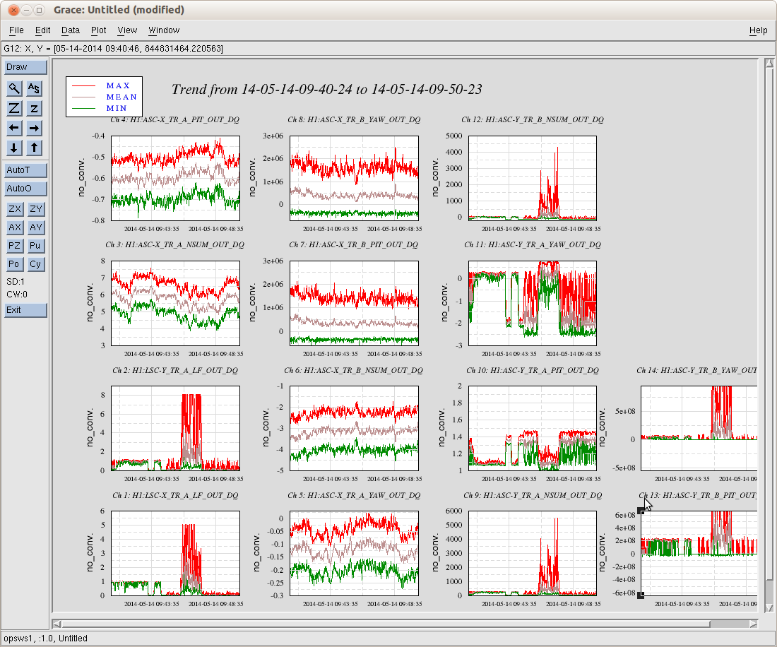
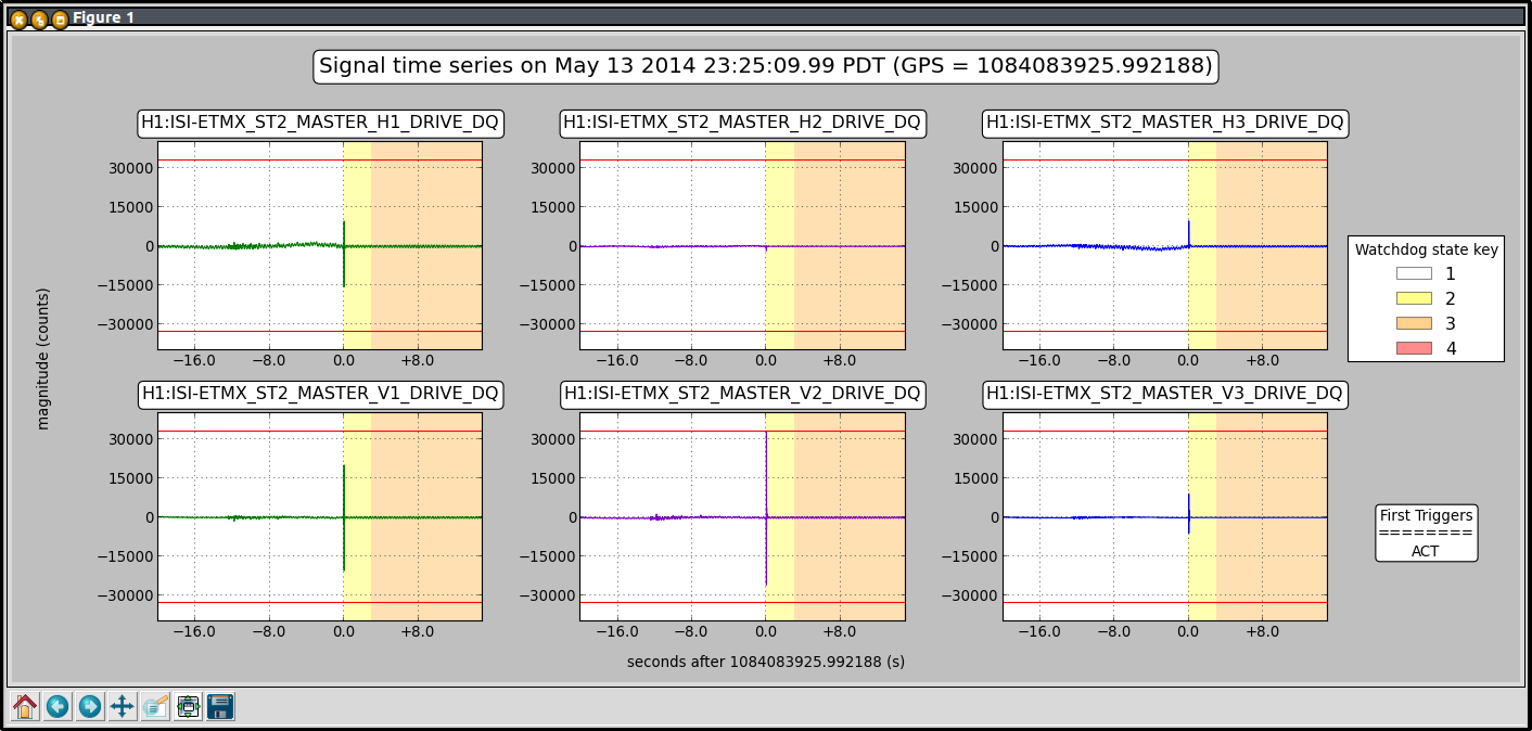
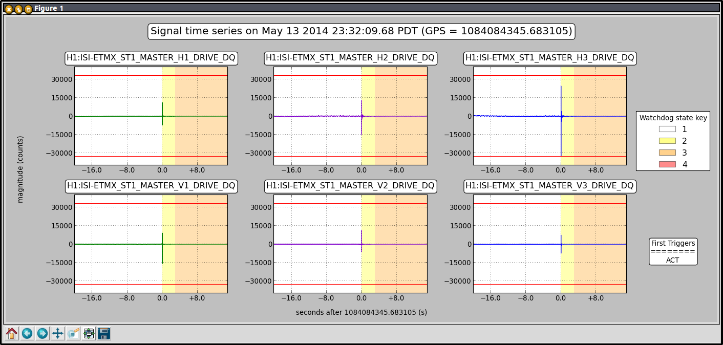
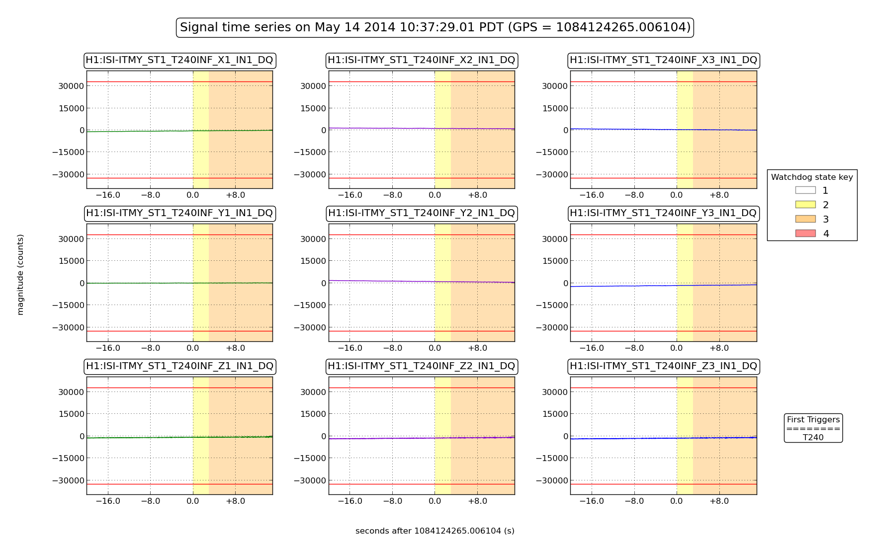
Immediately after the gains turned on, the T240 watchdog tripped. However, this appeared to not be associated with any actual activity in the T240 (see attached plot of T240 trip which shows nothing).
We suspect that this must be due to a bug in the watchdog code. A recent change activates the T240 watchdog based on the state of the stage 1 isolation loops: no T240 watchdog when the isolation loops are disengaged, and yes T240 watchdog when the loops are engaged with non-zero gain. It must be something to do with this logic. Fabrice and I are investigating.
The problem comes from the saturation counter that is not reseted:
- the T240 saturation flag turns on when we apply the HEPI offsets
- the saturation counters reach the treshold value (10 saturations)
- but the watchdog doesn't trips because the T240 are not in loop and therefore ignored by the top layer of the WD code. That's a feature we recently included so that we can turn on hepi without triping the ISI.
- as a consequence the saturation counters never gets reset
- so the WD trip when the T240 isolation is turned on, because the saturation counter flag is still on
Jamie and I have a plan to fix this. We need to modify the WD code and the simulink model. Dave says we can add those chances to work permit #4626.
I was told before that only one of the QPDs on TMSX see the IR transmission. I wanted to see how bad the problem is, so I looked at the the QPD signals for X and Y when night people were having night locking fun.
I'm disappointed to see that both of the X QPDs see nothing (attached, ch3 and ch6). QPD matrix elements and gains are correct, it's just that there's no photon. How come?
Y looks OK.
I saw an entry in the LLO log where they were able to flash the QPDs through a viewport during a time when they suspected they had a non-functional transmon QPD. If you begin to suspect the actual QPD functionality, perhaps you can try that. Otherwise, you can always give me a call and we can go over a functional check to be done chamber-side.
too far out of alignment.
Daniel told me that, after people played with X IR QPDs and saw some light, he moved picomotor of M4 (that is the harmonic separator the reflects IR but transmits green) because there was no IR on ISCTEX any more. After Daniel's treatment no IR light was seen on QPDs.
That's a long time ago.
No, Rich, I'm not suspicious about electronics.
model restarts logged for Tue 13/May/2014
2014_05_13 06:01 h1fw0
2014_05_13 10:48 h1hpietmx
2014_05_13 10:48 h1iopseiex
2014_05_13 10:50 h1isietmx
2014_05_13 10:51 h1iopsusex
2014_05_13 10:53 h1susetmx
2014_05_13 10:53 h1sustmsx
2014_05_13 11:21 h1susetmx
2014_05_13 11:24 h1susetmx
2014_05_13 11:49 h1broadcast0
2014_05_13 11:49 h1dc0
2014_05_13 11:49 h1fw0
2014_05_13 11:49 h1fw1
2014_05_13 11:49 h1nds0
2014_05_13 11:49 h1nds1
2014_05_13 13:41 h1susetmx
2014_05_13 13:51 h1susetmy
2014_05_13 13:52 h1susetmy
2014_05_13 13:57 h1iopsusey
2014_05_13 13:59 h1iopseiey
2014_05_13 13:59 h1susetmy
2014_05_13 13:59 h1sustmsy
2014_05_13 14:01 h1hpietmy
2014_05_13 14:01 h1isietmy
2014_05_13 14:06 h1broadcast0
2014_05_13 14:06 h1dc0
2014_05_13 14:06 h1fw0
2014_05_13 14:06 h1fw1
2014_05_13 14:06 h1nds0
2014_05_13 14:06 h1nds1
2014_05_13 14:09 h1asc
Tuesday Maintenance Day. Early unexpected h1fw0 restart. Many model changes with two DAQ restarts to support new configuration.
launched a TF measurement on ETMY for Arnaud at around 6:28 local.
Measurement has completed
Stefan, Kiwamu, Sheila
We have locked ALS DIFF with a bandwidth around 10Hz. The first 3 attachments are some screen shots of the configuration we had tonight when locking ALS COMM and DIFF. The ALS DIFF guardian enforces some of these settings, it doesn't control the drivealign matrices or the ESD offsets.
To get this we moved the UIM/test mass blend down to take care of the 10Hz UIM saturations, added an additional high pass to the UIM to reduce the low frequency drive, then pushed our UGF to around 10Hz. We added three low frequency boosts to DARM, after that we were approaching the VCO noise that Stefan measured earlier using a IFR in place of the DIFF PD. We added the FDD back in, which improved the noise at high frequencies. Spectra of the suspension drives are attached.
We then locked ALS COMM on the side of the fringe, and adjusted the DARM offset to bring the IR roughly half way down the fringe on the Yarm. The attached screen shot has both the ALS DIFF PLL control signal calibrated in Hz and the TRY PD roughly calibrated in Hz, with no frequency dependence (so this is not to be trusted above a few 10s of Hz). The strip tool shows the time series of this.
Then we locked both arms on IR using just ALS. The attached screenshot shows them locked and both roughly on resonance, we moved the COMM VCO set frequency by 500Hz to bring both arms off resonance, brought it back on resonance and off again.
Next we locked PRMI on the 1f signals, and adjusted the BS alignment which resulted in better IR alignment in the Y arm. PRMI power build up was 80uW in POP18 at the highest, which is pretty good.
After this we went to ISCT1 and realigned the diff beat note, we see 18.5mV rms our of the BBPD now. The attached screenshot shows the GigE cameras and the IFO align screen with this alignment.
We then locked PRMI on 3f. To do this we disconnected the power from the BBPD for Alexa's POP beat note measurement, and took the RF cable from the table to the rack back for 3f. At the rack side Kiwamu took the cable routed to POP9 back to the 3f diplexer.
We succeeded several times in locking both arms using ALS, moving them off resonance, locking PRMI on 1f. We could transition to 3f signals, but PRMI was not very stable.
The BS ISI has been tripped most of the night.
I think that the ISI trip happened before the suspension trip, this was while we were locking diff. I also thought that the T240s were green before I untripped the watchdog, but maybe they weren't because the ISI tripped again as it was isolating.
I stongly suspect that the second trip is due to the bug Fabrice and I noticed in 11888
J. Kissel I've added the linearization algorithm to H1 SUS ETMX and ETMY, as sketched out in T1400321. I have not tested its functionality, since folks needed both ETMs to get back commissioning / exploring ALS DIFF, but I've created the first-draft MEDM screens, and filled in a few of the gains such that we can start testing tomorrow morning. The algorithm has been installed with a bypass, which will be engaged for the night on both ETMs. Three notes of importance the expert user: (1) For Stuart: I've installed these modifications into the QUAD_MASTER.mdl library part (where the only change was to replace the ESDOUTF with the ESD_ESDOUTF_MASTER, and change the DAQ channel list to store the new version of the ESD Basis excitation channel names), assuming that we'll need to propagate this is to all QUADs, but I have not committed the changes to the SVN. I did have to change the ESD_OUTF_MASTER.mdl to include the bypass, this *has* been committed to the repository, since LLO is still using a more stripped down version of the algorithm, unhooked from any library parts (see LLO aLOG 12390). (2) For Dave: This is a "time-bomb" for the QUAD ITMs, given that they use the changed QUAD_MASTER, but haven't been re-compiled. However, the change involves no top-level connection changes, so the ITMs should compile happily. I've edited the generic MEDM screens, so whenever the ITMs are recompiled, reinstalled, restarted, and restored, they'll just inherent the change. Also, we don't use the ESD on the ITMs, so no one cares at this point. (3) For Kiwamu/Stefan: As described in T1400321, this algorithm assumes that we want to operate at 1/2 the maximum force, and hence there will be a DC value of V_BIAS * (1 - sqrt(2)) always output on the V_SIG channels. Eventually, we want to be able to ramp this bias over to the bias electrode for noise considerations, such that the individual quadrant voltages have a mean of 0, and only AC signals. However, currently, this algorithm can't support this. ------------ Details First assumption: we never use the ESD for angular control. Otherwise the linearization process will get messy (even more messy than it already is) really fast. Gain/units allocation: The linearization algorithm is based on using physically intuitive units: force units of desired control signal (in some order of magnitude version of [N]) on each quadrant, voltage on the bias electrode [V_ESD], and a conversion factor, or force constant between them [N / V_ESD^2]. In order to obtain such a convention, we need to surround the algorithm with buffer filter banks that change the calibration in the the appropriate units in and out of the algorithm. As such, we have three new filter banks (follow along with SUS_CUST_QUAD_L3_ESDOUTF.png): H1:SUS-ETMX_L3_ESDOUTF_FORCE -- coverts the L3 stage control voltage into force units. Since the combination of the DARM filter and the Hierarchical Design filters take out all of the frequency dependence prior to this input, we only need to convert this into force units at DC. Since ISC has done the work to convert their control signal into [um], we only need the QUAD model to get the [N/m]. Such that we can see the force coefficient on an MEDM screen, we choose the nano order of magnitude, [nN], and the gain in this bank should be (1 / 0.0026 [m/N]) * 1e-6 [m / um] * 1e9 [nN / N] = 38462 [nN / um] H1:SUS-ETMX_L3_ESDOUTF_VOLTS_DC -- converts request DC bias into voltage on the ESD bias electrode [V_ESD]. This should also be a frequency independent gain, the value which depends on the preference of the user input. People seem to prefer to have the DC BIAS already in [V_ESD], so this bank will remain and empty pass-through for now. H1:SUS-ETMY_L3_ESDOUTF_DACCT -- these convert each requested voltage back into DAC counts, since these are the fundamental units of the DAC, which we know saturates at +/- 2^17 [ct]. Each ESD driver channel should be identical, and frequency independent (up to ~2 [kHz], a pole for which we don't compensate), so again, the filter is just a DC gain. That gain should be ESD driver gain * DAC gain = (1/40) [V_DAC / V_ESD] * (2^18/20) [ct / V_DAC] = 327.68 [ct / V_ESD]. And finally, the final input to the linearization algorithm needs the unit conversion from force to volts squared, i.e. the force coefficient, H1:SUS-ETMY_L3_ESDOUTF_FORCECOEFF. From G0900956, the force coefficient for the entire four quadrants is 4.2e-10 [N/V^2] (where the [V] in the denominator are the same [V_ESD] as above). We want the force coefficient for each quadrant, so we'll divide by 4 and then scale to the up appropriate order of magnitude: 4.2e-10 [N/V^2] * 1/4 [1/nActs] * 1e9 [nN / N] = 0.105 [nN / V^2] Stay tuned, I'm sure this all change tomorrow once I get things working, and I have a discussion on this gain allocation with more people.
J. Kissel for S. Ballmer Stefan noticed that the H1 SUS ETMY UIM (L1) UR and LL Coil Driver Current Monitors (specifically the FAST_IMON) H1:SUS-ETMY_L1_FASTIMON_LL_MON H1:SUS-ETMY_L1_FASTIMON_UR_MON are unresponsive to a DC offset. We should fix this.
For info : the only test that have been carried out yet (with Phil) to understand those non responsive channels was to measure the voltage between the monitor output and the anti aliasing chassis. For the 4 channels we saw a similar voltage readback increase when sending thousands counts, meaning the problem could come from anywhere from anti alias to model wiring. More details on the pb : here
I don't understand this at all, but I noticed that changing the polarity of the bias for DC channel as well as the offset of each quadrants changes the response of ESD measured by OPLEV.
I first set DC bias to 125000 counts, set the offsets of all quadrants to 51776, injected into each quadrants, one by one at 3.2Hz, and measured the transfer coefficients from the excitation to the OPLEV. No filter in the injection path, so this is the TF from ESD digital output to the oplev. Injection amplitude is either 40000 or 20000 counts.
Then I flipped the DC bias and offsets, but without flipping the signal polarity, and repeated the measurements at 3.19 Hz. The TF polarity flipped as expected, but the TF amplitude increased overall by a factor of 1.2-ish if you look at PIT, or 1.6-ish if you look at YAW.
In the attached, left two panels show PIT response, right YAW. In in each panel, to the right is non-flipped data set, to the left is flipped.
This is highly repeatable, the measurement error seems to be 5% or less. The results don't depend on the excitation amplitude (this is expected).
From the fact that the TF polarity flipped though the excitation polarity stayed the same, this cannot be just electronics coupling into OPLEV.
Keita, Do you suppose it is simply that the force is proportional to (Vsig-Vbias)^2 ? RW
My point is that it should be proportional to (vsig-vbias)^2, but it doesn't appear to be.
Expected behavior is that when you flip the sign of vbias without flipping vsig, you will have exactly the same amplitude (which is not the case in my measurement) but with exactly the opposite polarity (which is the case in my measurement).
Since I'm not measuring vbias (I just trust the DAC counts), it could be that there's an offset in ESD driver, but the offset should be huge.
Charge?
DaveB, JimB, CoreyG, RickS We recently discovered that the PDA DC and PDB DC readouts on the MEDM screens were about a factor of ten lower than they had been. After some investigation today, we found that the gains in the filter modules had been changed from -1 to -.116 and -.108 respectively on March 18th. The safe.snap file has the -1 values. Not knowing why or how they changed, we changed them back and the MEDM screen now has the normal appearance, with the "DC" signals about 5 times the "AC" values. The voltages measured on the inputs to the ISS Servo module in the LVEA, from which the "AC" and "DC" output signals are derived, are about 1.7 V, same as the "AC" values on the MEDM screen. The servo seems to be functioning normally. Note for operators: The ISS varies the amount of light diffracted out of the PSL beam such that the "AC" output of the selected photodetector matches the "requested" REFSIGNAL value. Thus in the attached photo, the PD A Output AC value of 1.67V equals the requested -1.67 V (opposite sign). Photos attached: Left side of PSL ISS screen. Filter module before making the changes today. Filter modules after making the changes today. Matlab script for the "Cali-mean" F1 filter. Note the gain of -4.91999.
Comparing to Den's LLO alog 12590, we have about 10 times more DIFF noise at 10Hz, PLL locked, DIFF not locked. This turns out to be crucial for actuation range. So we looked at our DIFF noise using a simulated beat note, generated using an FM modulated RF source. The first two traces of the attached plot show the noise using a fixed-frequency (unmodulated) RF source. The first (red) uses the additional /10 frequency difference divider (FDD), the blue doesn't. note that the blue trace is pretty close to the noise seen at LLO. Traces 3 and 4 show the noise using an additional 0.3Hz, ~45kHz amplitude FM modulation, again with and without FDD. While the signal seems suggestively close the our in-lock signal (black), the interpretation is not straight forward. - We noticed that the hight frequency increase was at least part to an imperfect digital modulation drive of the RF source. switching the RF source to an IFR affected the noise level at high frequency. - Up to about 10Hz this seems to be an (unresolved) harmonic forest from up-conversion. Unfortunately I can't say for sure from which source - the IFR actually gave me worse noise at low frequencies.
David H and Greg G - CO2 laser on the TSCX table had run overnight, no issues with temperatures or output power. Was turned off at 1015 local time for some testing by Aidan, as he was looking at the dark noise of the ISS PDs. - Corner Hartmann table optics continued to be mounted and positioned. Minor adjustments made to the position of some on-table cables. - TCSY laser table work: continuation of alignment attempted but due to some irregularities in the positions of the first few optics (beam splitter, polarizers), with regards the relative positions of the laser and periscope, the co-ordinates of the table holes were relabeled and the table layout will likely need to be adjusted slightly. TSCX laser was turned on again at ~1715local and will run overnight. Table doors are locked. TSCY chiller and power supplies have been left running, TCSY laser is turned off.
- TCS to HWS table in LVEA - Corey to MY - Jason to HAM5 for alignment work - Jeff to HAM5 - Praxair on site - Paradise Water on site - CDS for external users going down, J. Hanks - DAQ reboots for SUS model changes - Rick going out to PSL area to look at ISS
After Sheila saw some excess angular motion caused by the length drive, I tried improving the decoupling of EX and EY UIM.
[Keita Arnaud]
Measurements live in /ligo/svncommon/SusSVN/sus/trunk/QUAD/H1/ETMX/SAGL1/Data called 2014-05-13_H1SUSETMX_L1_{L/P}2PY.xml