The "in chamber" SR2 open light values are :
M1T1 25373 1.182 -12686
M1T2 26012 1.153 -13006
M1T3 24840 1.208 -12420
M1LF 30482 0.984 -15241
M1RT 24731 1.213 -12366
M1SD 25027 1.199 -12513
M2UL 24112 1.244 -12056
M2LL 26045 1.152 -13022
M2UR 23920 1.254 -11960
M2LR 25085 1.196 -12543
M3UL 24821 1.209 -12410
M3LL 24674 1.216 -12337
M3UR 23869 1.257 -11934
M3LR 23932 1.254 -11966
A new safe.snap was made and the spreadsheet E1200343 was updated
Today while doing the PSL check I found the ISS Diffracted Power out of range (5-15%). It was about 41.6 %. With Sheila assistance I was able to fix it by incrementing the ISS Reference Signal value.
Framewriter 0 was stopped for a few minutes to move the raw minute trend directory to a different name. The raw minute trend data will be copied to the SATAboy hard disk array over the next couple of days, so older raw minute trend data will not be available from h1nds0 during that time.
I prepared two new GigE camera that are for monitoring the ALS X and Y green light. Currently the cameras and interior cables are temprarily put on the left corner in ISCT1. The external ethernet cables are not yet pulled and hence no ability to use them in the control room at this moment. The attached shows a picture of the cameras, their mounts and serial numbers of them.
The following HEPI Saturation Counters have been reset: HAM4 ITMx(BSC3 BS ITMy(BSC1) ETMy(BSC10)
Find attached the watchdogs trips summary of last week/beginning of this week. We'll discuss about it during the SEI portion of the testing meeting today.
8:15-8:35 Fred, Richard, Cyrus, Betsy, Richard, Filiberto, Aaron, Gerardo, Jeff B, Matt, Bubba, Travis, Hugh, Pablo, Mitchell, Justin, Mike, Thomas, Jeff K, Margot, etc. • TCS tables work continues. – (Matt, David, Thomas) • Contamination Control activities on HAM5 - (Margot/ Jeff B) • Getting SR3 ready for installation after reviewing the Hazard Analysis document- Jeff B • Continue Scraper Baffle work on HAM4 – (Betsy) • ESD work at End Y – Richard • Assembly work continues in Staging building – Jim • Suspension stages work continues(maintenance) – Jeff K • HEPI work (maintenance) - Hugh • Cavity baffle work in LVEA test stand - Travis/Mitchell
Crystal chiller refilled (180 ml added).
model restarts logged for Mon 05/May/2014
2014_05_05 00:37 h1fw0
2014_05_05 15:34 h1fw0
2014_05_05 16:30 h1fw0
2014_05_05 16:35 h1fw0
2014_05_05 16:39 h1fw0
2014_05_05 16:58 h1fw0
5 unexpected restarts followed by a reboot.
This morning we plan to shutter the PSL for a bit for TCS work. Richard and I put some of the Guardian managers in a paused state to prevent it from continually trying to relock the IMC. Specifically, we paused IMC, LSC, ALS_YARM, and ALS_XARM.
Stefan, Alexa, Jeff, Arnaud, Sheila
On saturday I took the FDD out of the DIFF PLL loop, this keeps us in the linear range of the sensor whenever both cavities are locked. Since this means that the VCO gain is reduced by a factor of 10, we added a factor of 10 to the DIFF PLL COntrol signal gain and reduced the PLL input gain by 20dB, it is now 6dB. The control signal noise is the same with and without the FDD in, as long as the ugf is the same.
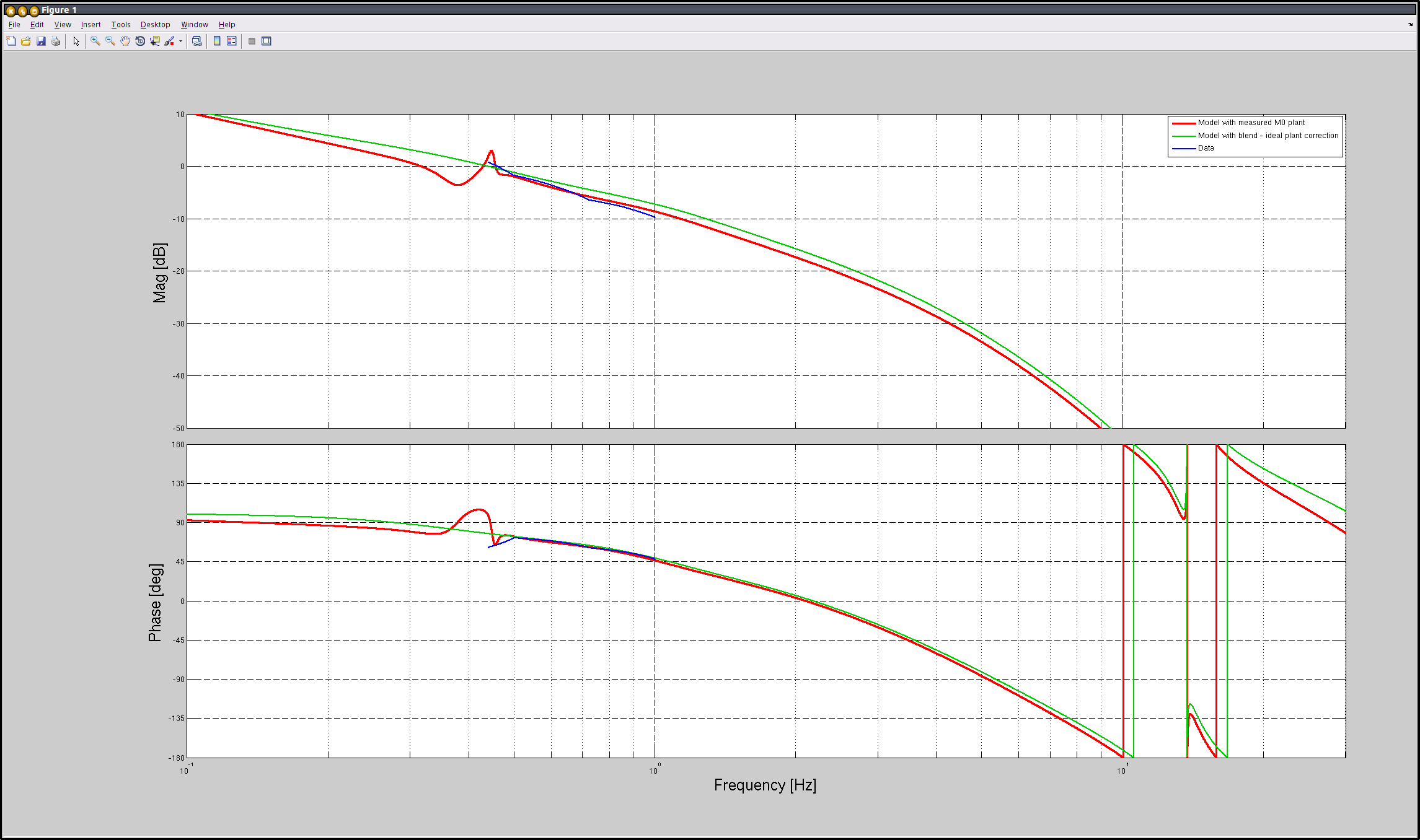
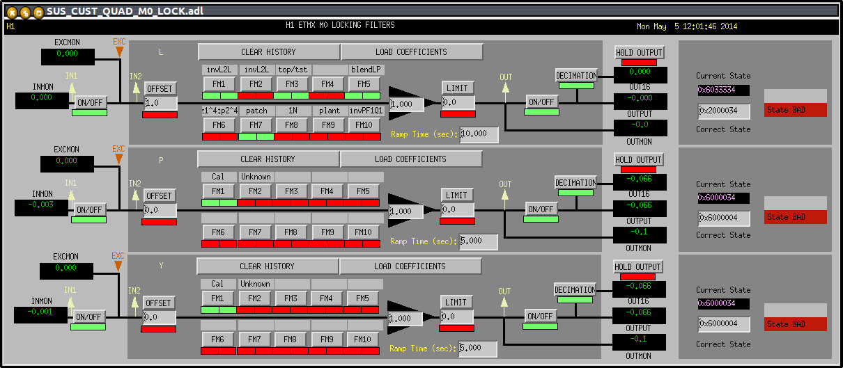
Stefan worked on making the plant inversion at low frequencies the same for the UIM as for the test mass, since the resonances below 2Hz are all common to the two stages. Arnaud fit the high frequency part of the UIM plant inversion measurement from over the weekend.
Stefan then adjusted the relative gain between the top mass and UIM by sending an injection to each stage with opposite sign and canceling the signal.
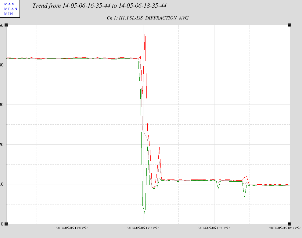
We began trying to lock DIFF. We needed to re align the beat note to get -23dBm. After that the locking went pretty smothly with only the top mass and UIM, we measured the loop gain at a few points and think that our UGF is 0.45Hz. This suppressed the fluctuations in DIFF to around 0.2um. We need to engage the feedback to the bottom mass to get more low frequency gain and a higher ugf.
We repeated the gain balancing for the ESD drive using the top two stages to balance the ESD drive, with a DC offset of 125000. When we engaged the test mass feedback, the loop rang up at around 0.3Hz.
Attached is a plot of the modelled OLG for feed-back with TOP+UIM. Red is the OLG model with the original plant data for the TOP mass, but the newer (patched) version of the inversion filters. Green is the model with an ideal plant inversion. Blue is the (5 data points of) measurement data.
Unfortunately h1fw0 could not wait until tuesday maintenance for its solaris server to be rebooted. Its daqd process went very unstable this aternoon so I decided to power cycle the solaris QFS server early to nip this in the bud.
The process is:
Lets hope this makes h1fw0 stable again. The solaris box did not crash or freeze, so I did not collect any stats. This was a preventive reboot.
LVEA Laser Hazard All Day
900 – FOM video4 found to be hung, Cyrus did some magic and then ops reloaded ST and MC cams
915 – TCS crew energizing laser at TCSX and continuing table buildup at TCSY
930 – Jeff B/AndresR installation prep at HAM4/5
1009 – Richard was in the control room when ETMy happened to trip
1030 - Betsy/Travis to EY on looking for parts
1030 - Justin/Sheila updated SUS_CUST_QUAD_OVERVIEW.adl to show the correct labelling for the lock filters
on L1 and L2
1053 – Apollo finished installing HAM arm at HAM5
1110 – Kyle to EY to look at vacuum rack
1147 – Fil to EY to work on ESD cabling
1300 – Confirmed with Sebastian that guardian manager deliberately paused for BS-ISI
1309 – Betsy/Travis to west bay LVEA
1436 – Corey taking tour to LVEA
I was looking over the PSL this morning and I noticed that in addition to the changes mentioned in Rick's aLOG from last week there was a sharp increase in the diffracted power in the ISS. From 10% to 41% diffracted power. Could this have something to do with the decrease in the transmitted (and sum) light for the PMC? The power decrease in the transmitted light from the PMC and the increase in diffracted light are both around 30%.
Travis, Betsy
Today, we finished rounding up the last few items in preparation to install the 4 baffles on HAM4 (Mitchell had a chunk of the hardware staged). We also reassembled the SR2 Scraper Baffle which had been contaminated and re-cleaned a month+ ago. It and everything we need is staged near HAM4.
IP11 was displayed as "RED" on CDS screens -> Found II422A +/- signal wires reversed on terminal strip -> corrected and "OK" or "GREEN" now indicated on CDS screens
Final alignment numbers for last weeks SR2 alignment (now that we have good TFs):
Sheila, Arnaud, Stefan Based on the model (both the sophisticated official, as well as a simple 4-mass, length only one) the transfer function ratio (TOP_L-to-TST_L)/(UIM_L-to-TST_L) is given by a simple pendulum resonance, namely the resonance of the top mass, assuming ass other masses are locked down (divided by the spring constant strength between TOP and UIM). Since we had a very good measurement of the TOP_L-to-TST_L transfer function below 1Hz, we trusted those poles and zeros, and simply updated the UIM inverse plant filter with the corresponding <1Hz poles and zeros of the TOP inverse plant. Next I copied the top mass blendLP to the UIM LOCK bank, and added a gain of -1. this allowed my to drive the nominally same signal through TOP and UIM, with opposite sign. Then I fine-tweaked the relative gain (and additional factor of 1.255 for the UIM drive), getting a drive signal cancellation of -39dB at 0.31Hz. THe same gain setting still gave me a cancellation of -26dB at 0.91Hz. I now trust the TOP/UIM blended actuator - onwards to the ESD! Attached are snap shots for the LOCK filter banks. (The UIM - the one with the gain of 1.255 - has the wrong title - the MEDM needs to be updated.)
Have noticed odd behavior with the HAM4 Dust Monitor (listed as #1). Have gotten MAJOR alarms for 0.3um particles (several hundred up to a few thousand counts!). Conversely, 0.5um particles has been virtually 0 for days. Mentioned high counts to Betsy before she went out to HAM4 today, and she mentioned that she only saw small counts out there on the floor. So there seems to be a discrepency some where.
Attached is a trend of the last 5-days. Will send an email to Jeff B.
This dust monitor looks to have fishy readings. Why are there lots of particle counts of 0.3um size but 0 counts on the 0.5um size? When I looked at the physical monitor a few times throughout the morning Friday, 0.3um always was reading ~10-30 counts, while 0.5um was reading 0. There must be some calibration diff between what reads on the actual monitor screen and what reads out in the control room trend data. Never-the-less, it's hard to think of how we could be dirty at 0.3 but not at 0.5.
Note - I asked Arnaud to recheck these since we already had the lower stage OSEMs pulled back for the IAS alignment. As well, I discovered that the top mass blade tip EQ stops are the rattle-loose kind so I need to now swap them in-chamber. So, I pulled the top 6 BOSEMs off as well - a good time to recheck the OLV settings of all OSEMs.