(Filiberto, Aaron, Thomas, Daniel)
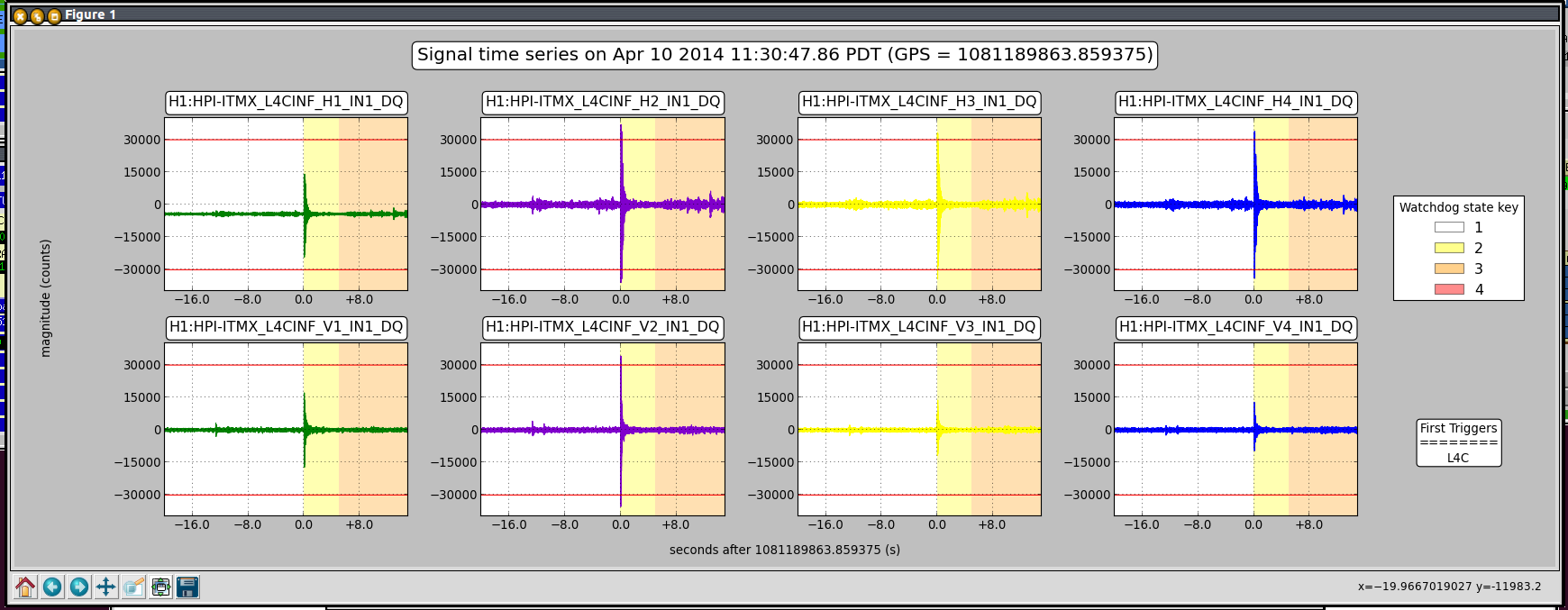
We installed the baffle PD amplifiers for ITMY. This is a new double chassis, so we replaced the old single unit. This should also fix channel 4 for the ITMX diodes. Previously, channel 4 was connected to channel 3, but now is back on channel 4. The TwinCAT system has been reconfigured to recognize the new channels.
I switched from fan 1 to fan 2 at Y end Fan 2 on at 11:39 Fan 1 off at 11:40 Fan 2 set to 12K flow
ITMX has tripped twice this morning, no known cause for the first trip, the second one we caused.
ITMX and ITMY both tripped in the last few minutes. Jim is recovereing. Phil and Aaron are pulling cables, these might be a good example of times when overly sensitive watchdogs make it difficult to commision while there is normal install activity in the LVEA.
Jim, Rich, Sheila,
several more trips, BS, both ITMs.
Rich and I tried to put ITMX into a safe state:
GS13 and L4Cs in low gain mode, all blends on Start, raise T240 watchdog threshold, Sensor correction off.
After we heard that Fil and Aaron are out of the LVEA I tried switching back to the good performance state, it trippped again while I was switching blends.
Why do these trip while switching blends? According to Rich that shouldn't happen, but it does. The second attached plot below is the actuator trip that happened while I was switching blends.
Dave H, Alastair, Thomas, Greg Quick summary of progress: TCSX: Laser was operated for a few hours on Monday with an output power of ~58.5W. Optics have been mounted and placed in position on the table. This table is now ready for alignment. TCSY: Optics/mounts have been staged, and are ready for table installation. Cabling is almost complete. Attempts were made on Wednesday to operate the laser/test the output power, however this was unable to be performed due to a fault with the paddlewheel flow meter (amongst other interlock/laser controller issues that are still to be tracked down). Some additional cabling is still to be installed. TCSX/Y periscopes have been partially assembled, still to track down one last component. Socket head cap screws with lower profile heads have been ordered, as it was observed that the cap screws for the periscope base sit proud.
TCSY paddle wheel flow sensor power checked and settings confirmed. Still unable to display water flow value. Will need to remove from system and check operation on the bench and/or replace.
DavidH/Greg : Paddle wheel flow sensor removed, tested and was found to be working as expected. Reinstalled/reseated and now appears to be working correctly. As per installation instructions, for this install no teflon tape was used... previously used tape was removed.
Power watchdog trip, Gerardo is making plots to investigate.
Threshold raised
model restarts logged for Wed 09/Apr/2014
2014_04_09 07:27 h1fw1
2014_04_09 12:17 h1hpiham4
2014_04_09 12:17 h1hpiham5
2014_04_09 12:17 h1iopseih45
2014_04_09 12:17 h1isiham4
2014_04_09 12:17 h1isiham5
h1fw1 unexpected, all others due to power down of h1seih45.
No touching, please.
Yesterday, Scotty and I were able to populate the 400+ 1/4-20 hardware into the stage 2 closeout plate cover, as well as attach the back and side ribs. Today, I made a cable kit for 3IFO BSC unit 2. Unit 3 will need 4 cables tested before it is a complete kit. All bolts connecting the closeout plate and closeout plate cover were torqued to spec. Locker sub-assemblies have begun. General cleanup and shelf organization is also ongoing.
9am Justin HAM2 area working on laser barriers
9:15 DaveH & Alastair to LVEA for TCS work
9:30 Hugh HAM4 HEPI work
9:30 Fil & Aaron to EY for camera install
10:30 Bubba to EX
10:30 Ark Roofing on site
10:45 Corey to LVEA looking for cameras
12:00 Fil & JimB powering down HAM4/5 rack for fix BIO cabling
I didn't hear from anyone after lunch, so I'm assuming all work stopped about then.
(Alexa, Pablo)
We examined the noise spectrum of REFL_DC_BIAS in several configurations. The first was in the nominal setting. We then placed an ND filter along the PSL reference path on ISCT1 after the shutter. Finally, we placed the ND filter along the x-arm green transmission path (before ALS-BS5). We saw that the beatnote signal appropraitely decreased by 3dBm (or Sqrt(2) in amplitude) with the ND filters placed. This signal was taken from the RF MON readback; I confirmed that this was consistent with an RF anaylyzer after the RF pre-amp.The 1/f noise changed by the same amount regardless of which path the ND filter was placed in. Surprisingly, the noise increased by a factor of 4. One would imagine only an increase by sqrt(2). This increase is also higher compared to what we saw when we did this measurement yesterday (alog 11221).
REF # | ALS-C_TRX Cnts | Beatnote Signal | |
No ND Fiilter | 4,5(RMS) | 0.85-0.93 | -14.6dBm |
ND Filter in x-arm trans path | 6,7(RMS) | 0.35-0.48 | -18dBm |
NF Filter in PSL ref path |
2,3(RMS) | 0.80-0.94 | -18dBm |
While on the table, I noticed that there is clipping in the PSL reference path. The beam is clipped at the bottom of the PBS. I have not done anything to fix this clipping yet. This will affect our mode matching and our noise.
Just for the record, plots attached to show the problem we saw on the horizontal corner1 HEPI actuator. The first and second plot shows the unmatched response slopes to the H1 drive. The third plot shows an acceptable result although it might be nice to normalize/overlay the traces but we are also looking at the calculated slopes so we aren't just sticking a thumb up and seeing if it looks ok, but almost. These acceptable slopes range from 1.75 to 2.00cts/ct. The first plot H1 slope is low at 1.35 and the second is too high at 2.6cts/ct. The PTB haven't given an explicit criteria, so, executive decision: if you have to look closely to see if the slopes are much different then they are ok.
A magnitude 8 earthquake coming from Chile tripped all the BSC-ISIs on 04/01/14. Sheila's wd plots show that the ISIs tripped on the actuator watchdogs. We suspected that the servo loops were trying to compensate for the common mode seen by the BSC-ISIs at both ends of the arms, thus saturating the actuators. We studied the ground motion recorded by the ground STS at the corner station (BS-STS) and the ground T240 installed at EX (EX-T240) at the GPS time provided by Sheila, in order to find out.
On the attached document:
We could considerably reduce the amount of signal sent to the BSC-ISI actuators during a major earthquake (factor as big as 6), and thus reduce the risk of saturating the actuators, by removing the common mode from the signal we feed to the servo loops of the BSC-ISIs.
Data, plots and scripts are commited to the seismic SVN:
/ligo/svncommon/SeiSVN/seismic/Common/Data/2014_04_01__Chile_Earthquake_Data/
Note 1: X and Y had to be swapped on EX data, and a minus sign was also added to the new x-axis EX data. It is likely that EX T240 is mis-oriented.
Note 2: The calibration of EX-T240 was still the one that JeffK made, at the time we looked at. RichM updated it since.
Units were updated.
Plots and script were commited to the svn.
We Left ETMX running over night (it wasn't very windy so this should probably count as a quite time, I need to make a tool that will tell me that kind of thing). Sensor correction was installed in three degrees of freedom last night and running. This is ground to stage 1, using Ryan's filter which is targeting the first suspension mode at 0.45Hz. I've attached three sensor correction plots on/off, blue is sensor correction off the other colors are sensor correction on with various gains. The X direction gain ended up at 1 (which is what it was designed to be) Y and Z came out to be 0.6, which is very weird. There are also three performance plots from last night, with the GS13 and T240 curves. In general we are buried in the GS13 noise above 0.5Hz (red vs green) except at the BSC pier resonance, we do not have the HEPI L4C feed forward filters installed yet. GS13 rY and rX tilt coupling (yellow line) explains most of the low frequency gs13 signal. There is clearly some room to relax rZ loop to reduce the gain peaking below 0.2Hz and again none of this is Stephen's fault I can't figure out how to change the login to me Rich Mabey I hope that I now have the correct plots
I added the projected motion at the suspension point (Longitudinal), where we aren't noise limited we are completely dominated by table X motion, which of course at low frequency is completely dominated by rotation motion (rY).
Yaw motion only couples to table rZ so I didn't plot that
added ETMX and ITMX optical lever signals
Latest curve. 11 days shown.
loglog plot also attached - note that the BSC6 annulus was probably vented until day 8. There may be a slope change after this date.
Here is a check list for setting up/working with the ground STS2s (or T240)
Before touching a STS2 the THREE test masses should be locked using the special non-magnetic screw driver, the T240s do not have locks and are more rugged
After you are done mucking with it
Make sure that it is aligned using the swizzle stick
Make sure that the instrument is levelled (bubble level on the sensor)
Make sure that the feet are locked (unlocked feet are not stable)
For STS2s unlock the masses using the special screw driver
Restore the thermal insulation (exactly what we need is not clear, but we know that at least an enclosure is important)
Zero the mass positions (this happens at the electronics racks) and read mass positions to make sure that it was successful
------------------------------------'
Eventually it is nice to take a transfer function from the ground instrument to a set of ISI platform instrument to check the alignment
Jim B, Filiburto, Jim W, Dave
we powered down h1seih45 computer and its IO Chassis. Filiburto installed a fourth binary cable to the output port of the second Contec card (HAM5's card). He disconnected HAM4's CN-B from the upper 32 channel input of the binary-output chassis and connected HAM5's CN-A to this port.
We powered up the system, verified that the new logging script worked.
Jim W verified binary output switching for both HAM5 and HAM4 is working correctly.
reboot log shows the startup as:
Activated the ETMY baffled diode amplifier in TwinCAT.