Displaying reports 721-740 of 88356.Go to page Start 33 34 35 36 37 38 39 40 41 End
Reports until 09:07, Wednesday 13 May 2026
H1 SPI
jeffrey.kissel@LIGO.ORG - posted 09:07, Wednesday 13 May 2026 (90223)
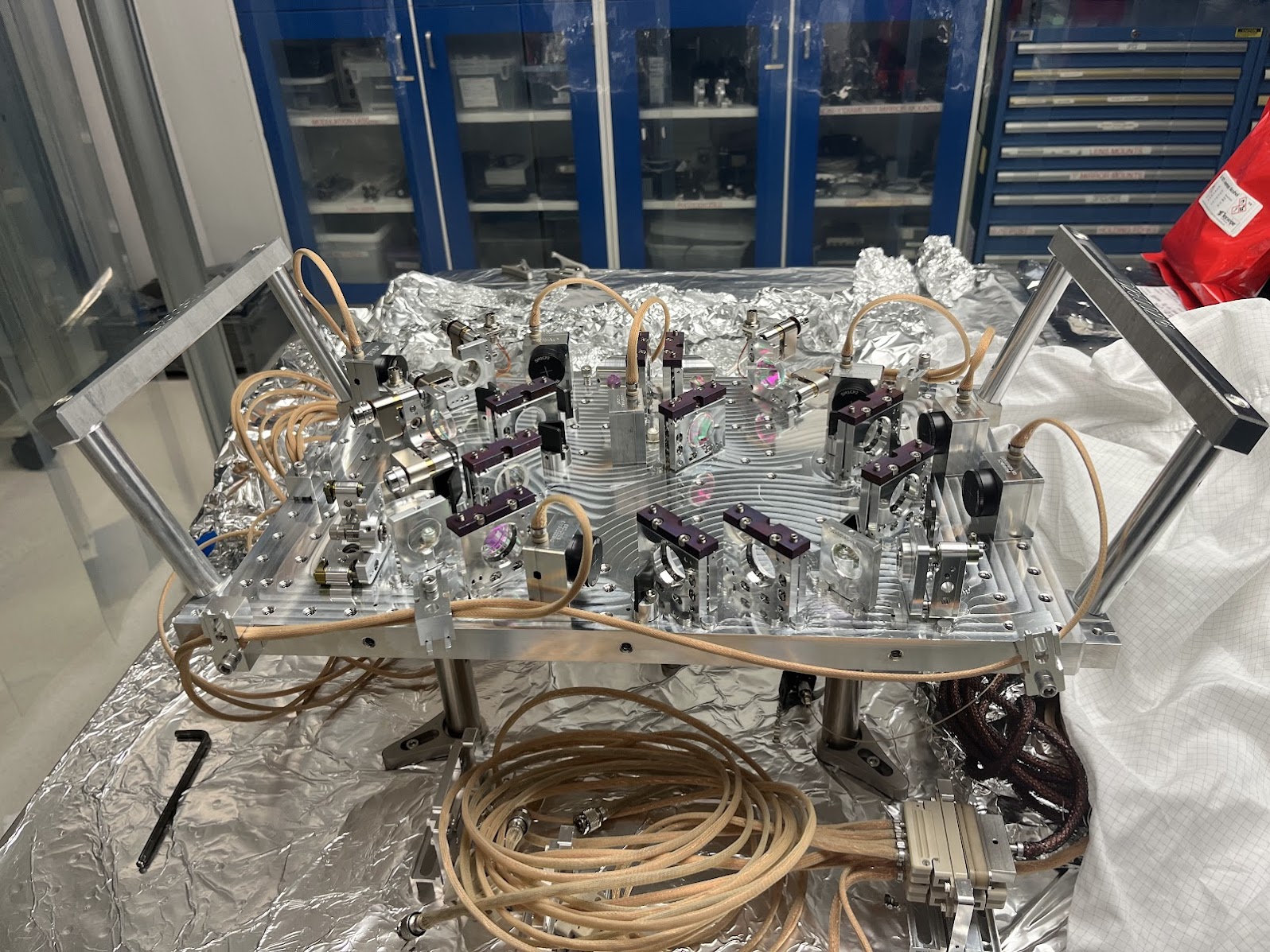
SPI Installation Handles Fit Check
J. Kissel
ISIK Transceiver Assembly D2400107-v5
ISIK Installation Handle Assembly D2500215-v2

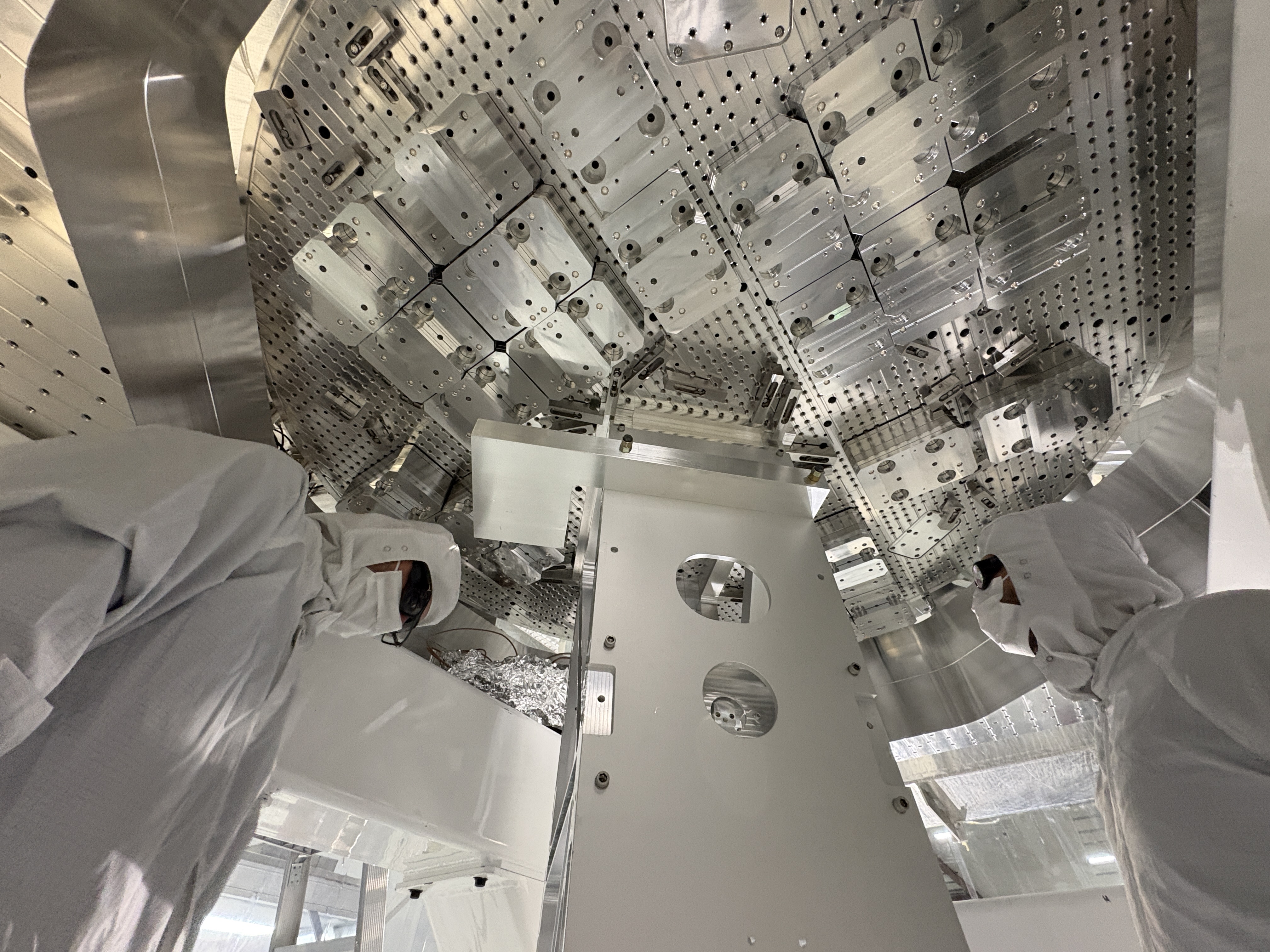
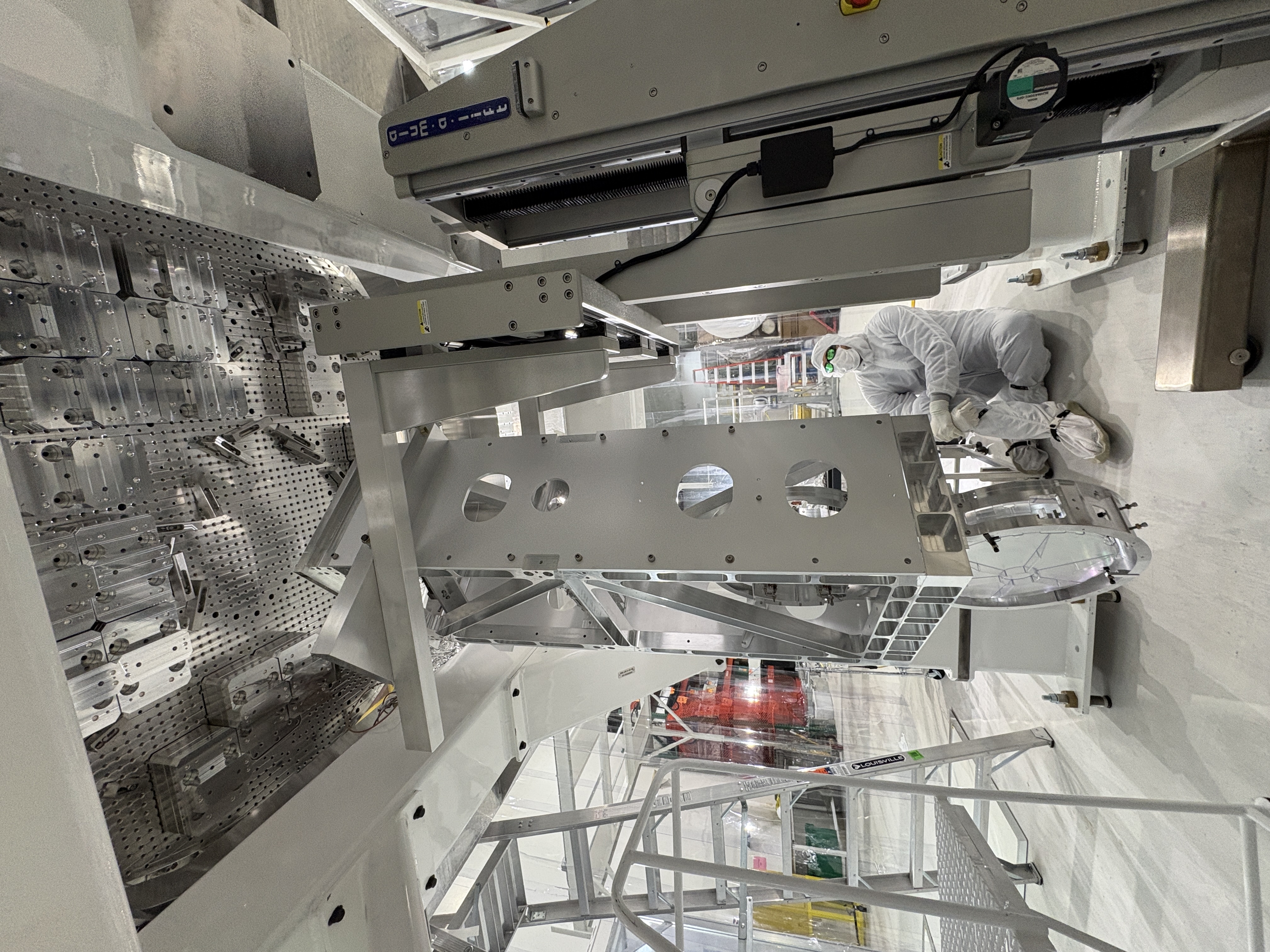
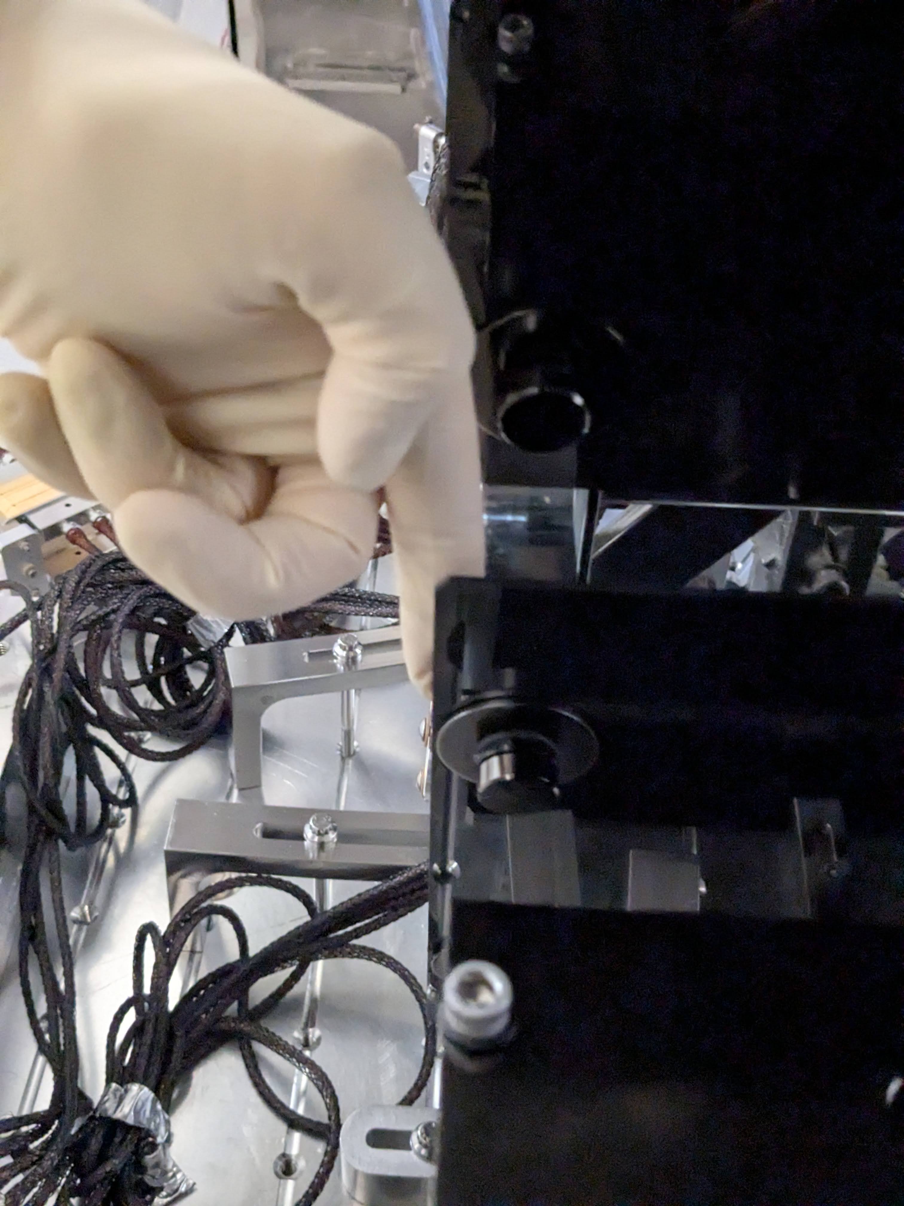
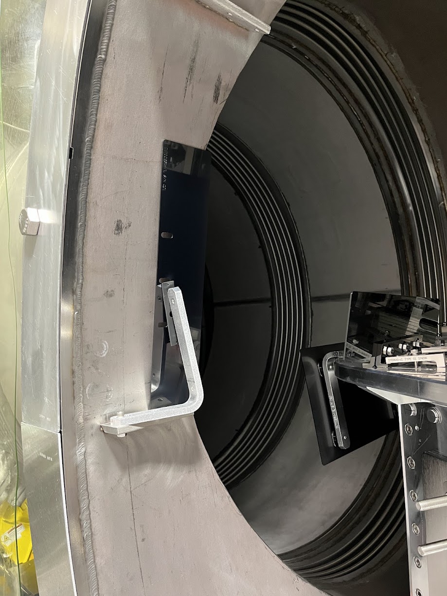
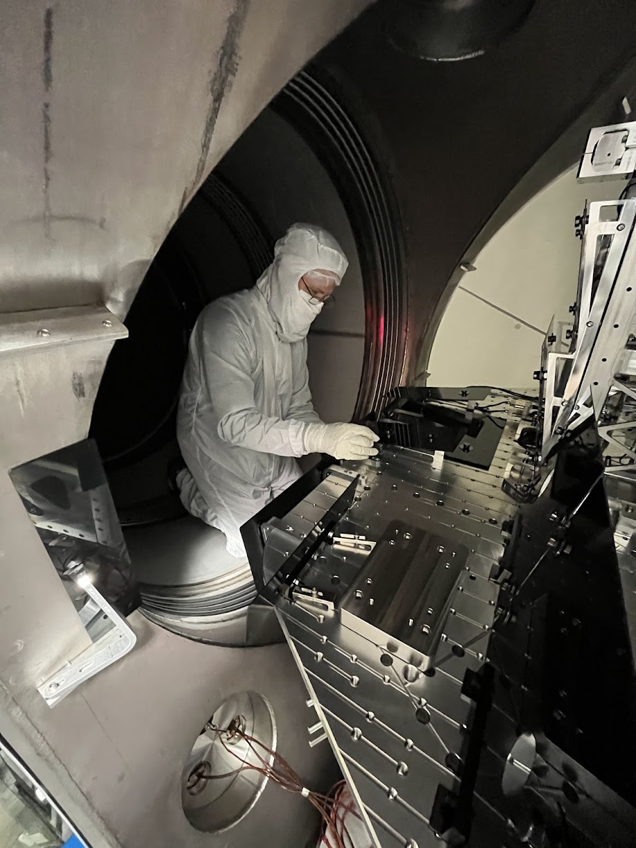
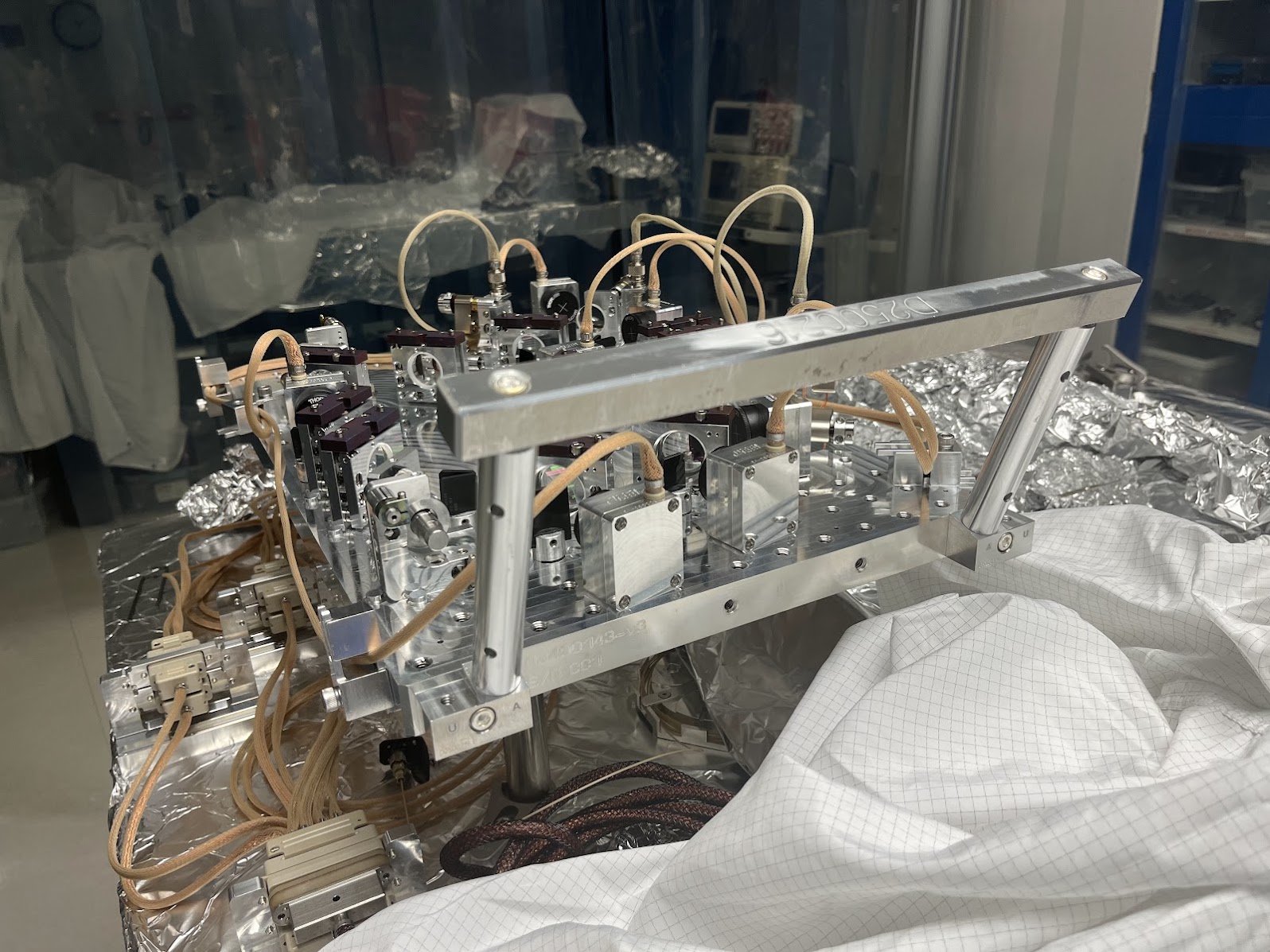
In prep for moving the old version of the SPI pathfinder's ISIK transceiver (D2400107-v4) with CVM100 mounts to the side, I assembled and fit-checked the (Class-B) ISIK Installation Handle Assembly D2500215. It fit! The only detail that required clock cycles was understanding which hardware went to which hole, so I made some redlines and posted them to D2500215-v2.

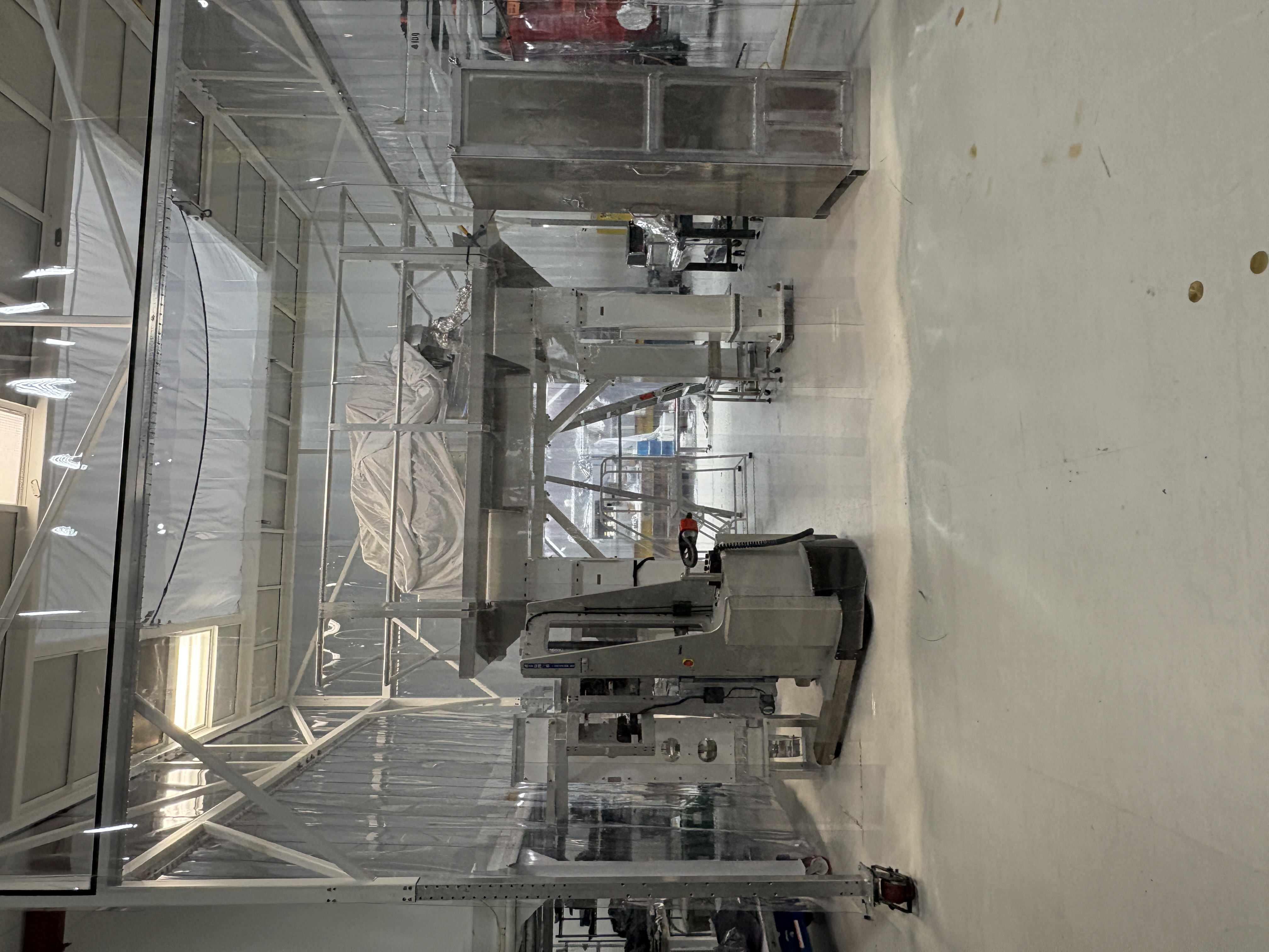
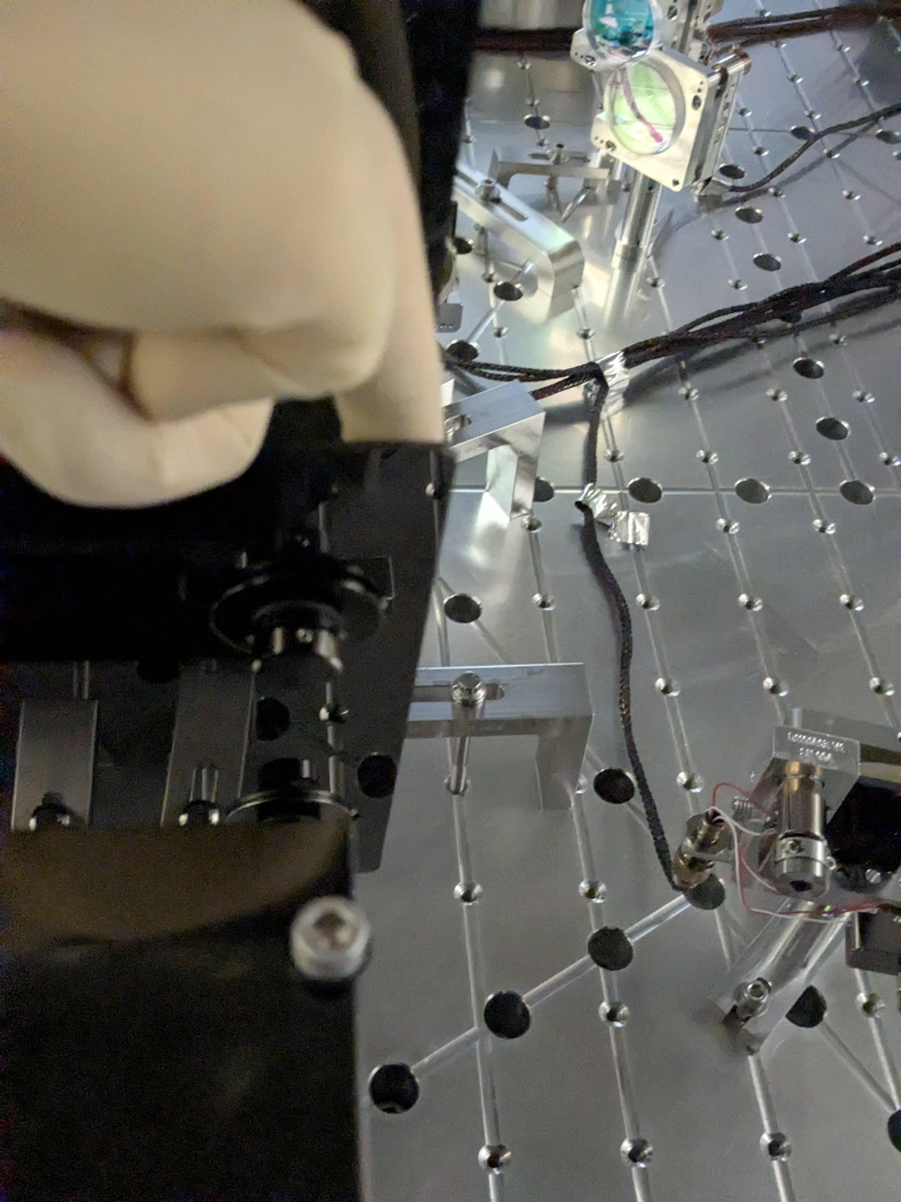
Attached are pictures before moving ye ol' 'board.

Nice work ANU!
Images attached to this report
LHO General
corey.gray@LIGO.ORG - posted 07:36, Wednesday 13 May 2026 (90221)
Wed DAY Ops Transition

TITLE: 05/13 Day Shift: 1430-2330 UTC (0730-1630 PST), all times posted in UTC
STATE of H1: Planned Engineering
OUTGOING OPERATOR: None
CURRENT ENVIRONMENT:
    SEI_ENV state: MAINTENANCE
    Wind: 19mph Gusts, 13mph 3min avg
    Primary useism: 0.04 μm/s
    Secondary useism: 0.10 μm/s 
QUICK SUMMARY:

ISS PD Array + LVEA Laser Hazard will continue.  BBSS work continues at the Test Stand.

Rainy & windy morning (just had quick wind storm with gusts reaching almost 50mph just passed...forecast is for a windy day).

H1 IOO
keita.kawabe@LIGO.ORG - posted 00:54, Wednesday 13 May 2026 - last comment - 10:19, Monday 18 May 2026(90219)
ISS path alignment: Not much progress on Tuesday due to distraction/confusion (Elenna, JennieW, Keita)

We started with yesterday's alignment. I checked flashes in ISS array PDs and didn't like that the balances between them were very much different from how they were when IMC was locked back in March.

Then we started changing IM2 and IM3 to see if we can get back, but I was appalled that the flashes became stronger and stronger on array PDs as we aligned, which probably means that the beam was almost falling off of the PDs when we started. 

That shouldn't have stopped us because we don't know where the beam was on the array PDs when MC was locked (people gave up optimizing that path because things didn't make sense), it could have been falling off of the diode (because each diode is 2mm,  QPD is 3mm, the beam size is ~250um or so, and the beam was almost in one quadrant of the QPD). But I started thinking about many what-ifs and wasted time.

After all, since IM4 TRANS and ISS array QPD are both reasonably close to March 2026 position, we know that the beam position as well as angle of the beam injected into ISS path from IM4 are already close to those when IMC was good in vacuum.

What we should do is this:

Other things to note:

This is not required for the alignment but it's helpful to know how much we can move the beam on QPD. In an unlikely event where we somehow lose the beam in vacuum on the array QPD after IMC is locked, we might be able to scan IM3/IM2 to regain the beam on QPD, and slowly move IM3/IM2 back to the nominal position while pico-ing so the beam isn't lost on the QPD. If the beam is not clipped, the beam displacement on the QPD is ~3mm per 1mrad of IM3 rotation using parameters collected from various documents, see attached script.

The same script shows you that the Gouy phase separation between two pico mirrors is 10 degrees (if we use the beam parameter in Matt Heintze's alog 12537, which was probably obtained by the measurement of the bypassed beam) or about 20 degrees (if we use IMC eigenmode parameter propagated to the ISS path using D1200693).

Another thing is, if we believe the design eigenmode number rather than the measured bypassed beam in Matt's alog, the beam waist will be smaller and at about 20cm upstream of the PDs. The beam size on the PDs is about twice as large as it should be (470um rather than 250um). I cannot measure the beamsize of the flashes so we won't do anything, but that's something to remember. If IM3 has enough actuation range, we can later lock the IMC, scan the beam across the PD until the beam falls off, see how sharp the fall-off is, and use the diameter of the PD (3mm) to determine the size of the beam. Maybe a good project for a fellow.

Non-image files attached to this report
Comments related to this report
keita.kawabe@LIGO.ORG - 09:10, Wednesday 13 May 2026 (90224)

One of the things that bothered me (that isn't directly related to ISS alignment) is the fact that we had to rotate JM3 by a huge amount, i.e. negative 200um in PIT to "center" the MC2 trans QPD. This is the equivalent of the negative YAW rotation of the beam in IMC's coordinates (clockwise seen from the top). Since the distance between MC2 and JM3 is ~19m according to E2400218, this means that the MC2 beam position was moved by about ~7.6mm in -Y direction on MC2. This seems to roughly corroborate with the pictures in alog 90203 ("before" picture and  "after", hard to tell how much it actually moved due to parallax but there's no doubt that the motion was large).

What if this is because something is wrong with the MC2 trans path? Like the pico mirror in front of the QPD was bumped (by a huge amount, however unlikely it is). My conclusion is that we can lock IMC in vacuum, use WFS with MC2 centering, measure the centering on MC2 using dither, and figure it out. If QPD center is grossly off from the MC2 center, we can pico.


keita.kawabe@LIGO.ORG - 10:19, Monday 18 May 2026 (90265)

Sorry the script in the above alog didn't work because it was missing one line.

Attached is a working version. You need a la mode matlab package https://github.com/nicolassmith/alm.

Non-image files attached to this comment
H1 SEI
jim.warner@LIGO.ORG - posted 16:43, Tuesday 12 May 2026 (90217)
Prep for CRS assembly in H2 PSL anteroom

Shoshana, MichaelR, Jim 

This morning we started moving parts into the lvea to start doing CRS assembly in the H2 PSL enclosure. We should have parts for 2 complete sensors right now (minus HOQIs), and should be getting the remaining parts out of clean and bake soon. We spent a lot of time trying to debug the H2 fans and hvac, but it seems not everything is fully functional yet. HEPA units are running in the anteroom however, which should be enough for us to keep parts clean while we assemble. I put a dust monitor in on a table and took counts, they stayed the in 50-100 range while I was watching. Parts are set on one of the stainless shelving units, we can use the stainless table in the anteroom for assembly for now. 

Images attached to this report
LHO General (OpsInfo)
thomas.shaffer@LIGO.ORG - posted 16:30, Tuesday 12 May 2026 (90209)
Ops Day Shift End

TITLE: 05/12 Day Shift: 1430-2330 UTC (0730-1630 PST), all times posted in UTC
STATE of H1: Planned Engineering
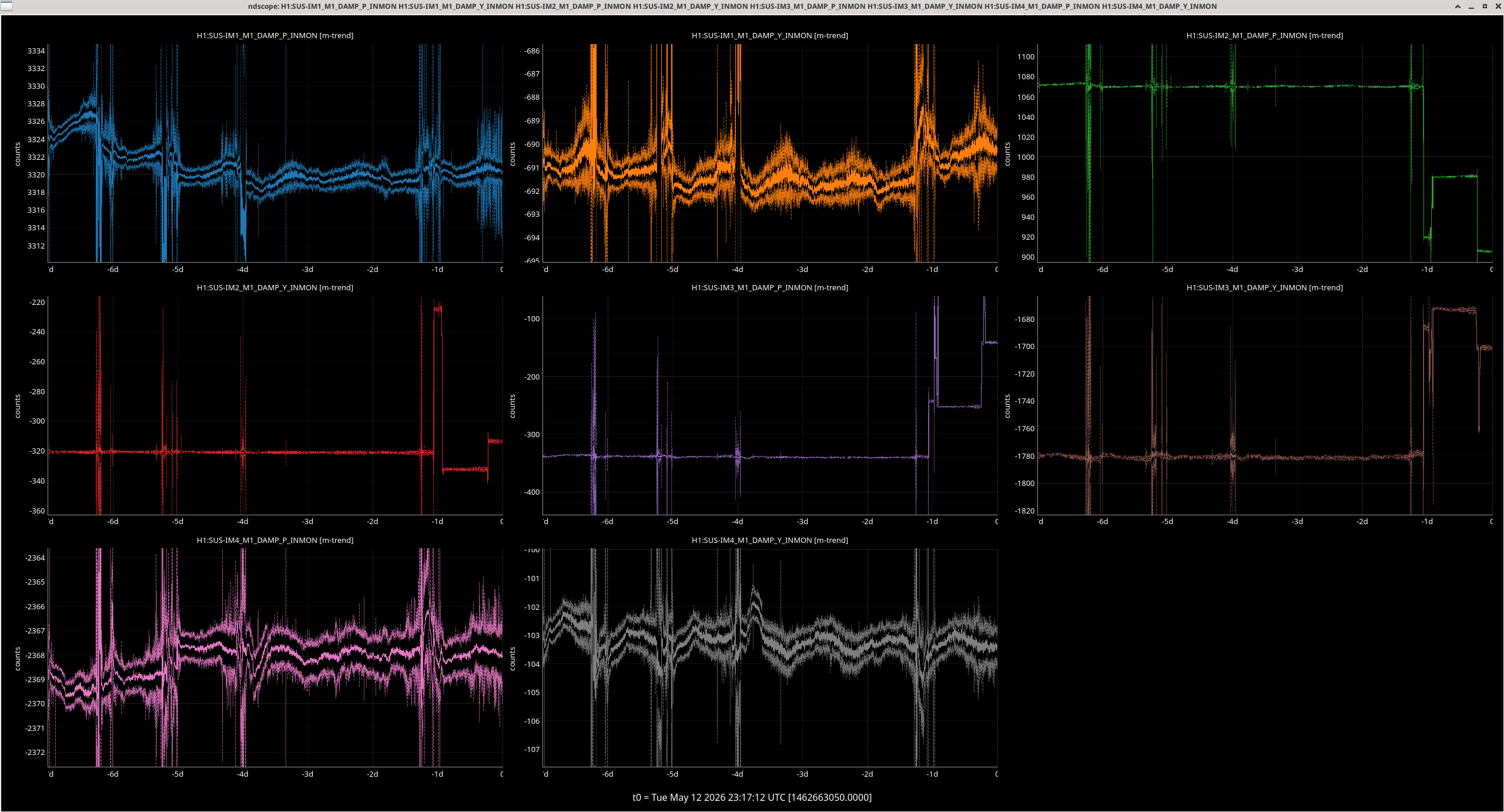
SHIFT SUMMARY: The BS suspension was removed from the ISI that it hung from today. The LVEA continues to be in laser hazard for the ISS swap work, which will continue on for another day or so. Alignment trends attached, no surprises with the ongoing ISS work.

Operators - It looks like the LVEA temperature has been trending up over the last week (see screenshot). We should keep an eye on this to verify that it comes back.


LOG:                                                                                                                                                     

Start Time System Name Location Lazer_Haz Task Time End
19:43 SAF LVEA IS LASER HAZARD LVEA Y LVEA IS LASER HAZARD 12:03
15:14 FAC Kim LVEA yes Tech clean 17:05
15:17 IAS Ryan C LVEA yes Warm up Faro 15:33
15:20 FAC Randy LVEA yes Setting up lights at test stand 15:58
16:05 FAC Randy LVEA yes Prep and setup 16:36
16:20 SUS Betsy, Rahul LVEA yes BBS bonding and sus prep 18:46
16:27 SAF Keita LVEA YES Opening light pipe 16:44
16:31 FAC Chris MY n Bringing battery charger 17:31
17:01 SUS Ibrahim LVEA yes BBS work 18:56
17:03 SUS Randy LVEA yes Assist with BBS 18:38
17:17 PEM Robert EX n Magnetic coupling investigation 19:31
17:31 SEI Jim, Michael, Shoshana LVEA yes Moving CRS into the H2 PSL enclosure 19:03
17:34 IAS Jason, Ryan C, Stephen LVEA yes Monument search and error hunt 19:56
17:54 FAC Kim LVEA yes Tech clean 18:48
19:32 SPI Jeff Opt Lab n SPI assembly 21:56
19:33 SUS Ibrahim LVEA yes BBS work 22:03
19:43 SUS Randy LVEA yes BBS work 22:03
19:46 SUS Betsy LVEA yes BBS work 22:03
19:57 CDS Marc, Josh LVEA yes SUS R2 rack testing out SPI electronics 21:42
20:27 SUS Rahul LVEA yes BBS work 20:35
20:28 SUS Travis LVEA yes Bringing out hardware 20:33
20:50 FAC Tyler LVEA yes Inspect scaffolding 21:05
21:02 NCAL Tony, Michael, Shoshana EX n Spin up NCAL 22:13
21:05 SEI Mitchell ends n HEPI FAMIS checks 21:46
21:22 PEM Robert EX n Magnetic coupling invesitgation cont. 23:23
22:28 SEI Jim, Michael, Shoshana LVEA y H2  anteroom CRS build (M & S out @2300) 23:07
Images attached to this report
H1 CDS
david.barker@LIGO.ORG - posted 15:55, Tuesday 12 May 2026 (90216)
FMCS Well Pump Monitor EPICS IOC

Jonathan, Erik, Dave:

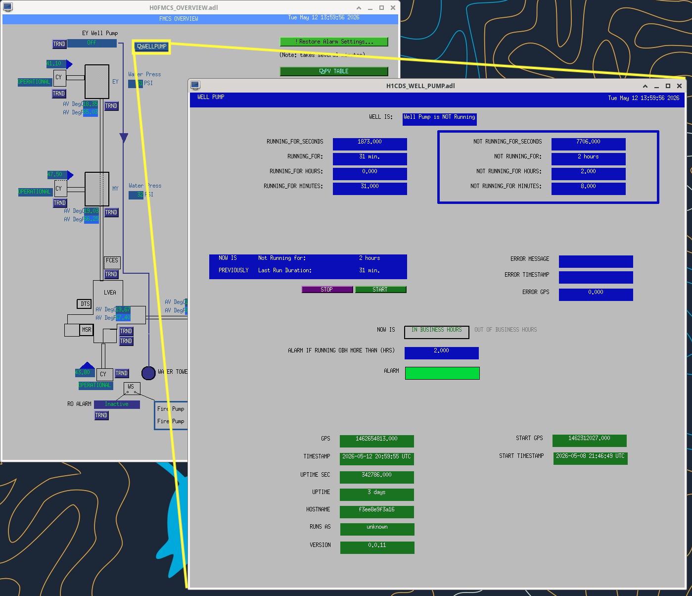
The EY well pump is now being monitored by an EPICS IOC which will report if the pump runs long outside of business hours. The well pump status is available on a MEDM, which can be launched from the FMCS overview MEDM (see attached). If the pump runs for more than 2 hours outside of standard hours (07:00 - 17:00 Mon-Fri) an alarm will be raised.

Images attached to this report
H1 SUS
ibrahim.abouelfettouh@LIGO.ORG - posted 15:14, Tuesday 12 May 2026 (90214)
BSFM lifted off of test stand/ISI

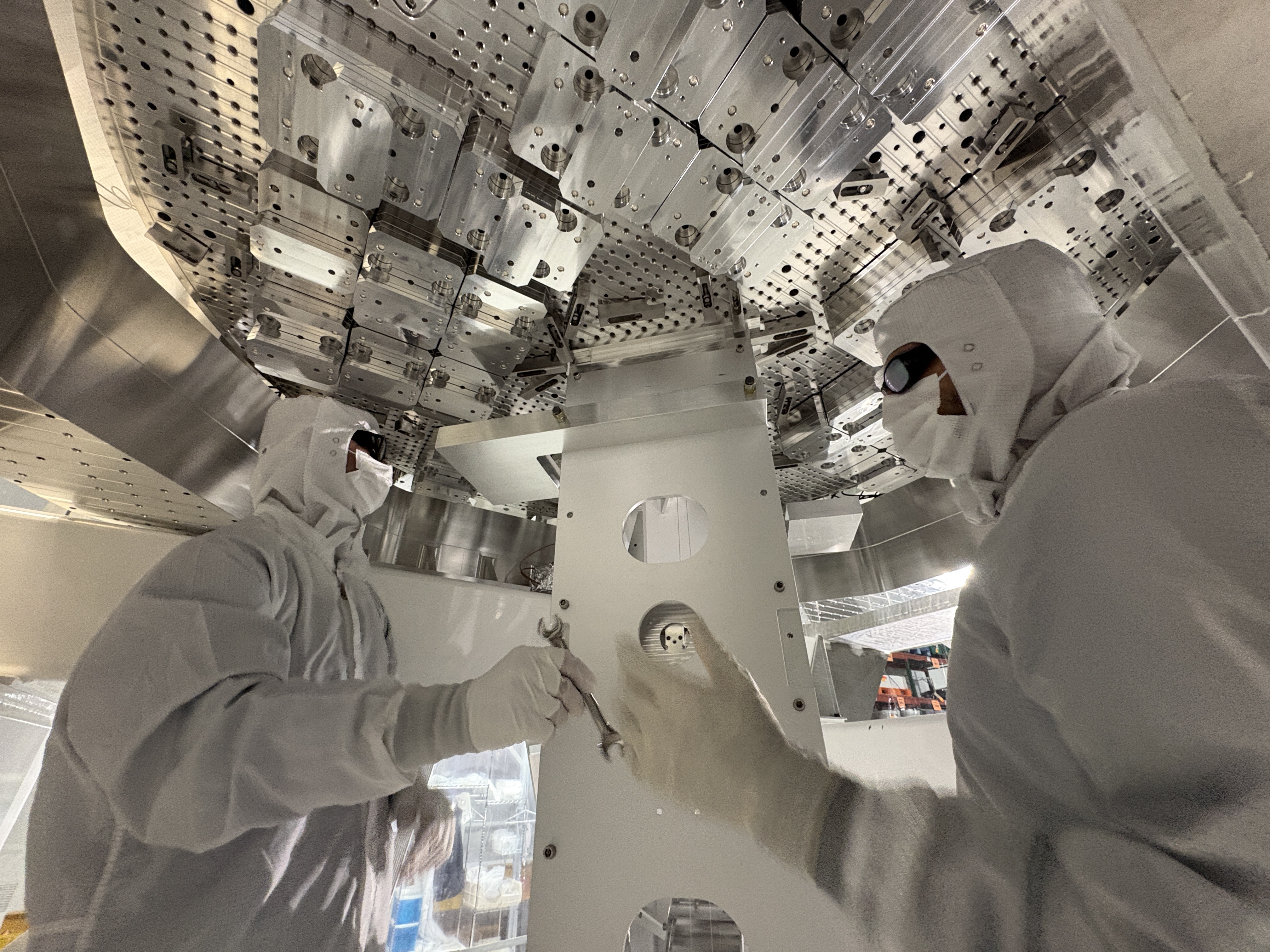
Ibrahim, Randy, Betsy, Rahul

Today, we:

See pictures


Images attached to this report
H1 SUS
oli.patane@LIGO.ORG - posted 11:01, Tuesday 12 May 2026 (90154)
BBSS SUS medm infrastructure filled in

I've gone through and filled in most of the infrastructure for the BBSS (found under BS/ITM on sitemap as BBSS temp). Values and filter settings have been saved to sdf and filters added have been committed in H1SUSLO12.txt as r35219. For the majority of the filters banks, I turned any filters that are shown as being on in whatever I referenced them from, but all filter banks have INP and/or OUT OFF, so no signal can pass through.

Infrastucture filled in:

All stages
OSEM2EUL / SENSALIGN / EUL2OSEM Matrices
Filled out according to matrices calculated in /ligo/svncommon/SusSVN/sus/trunk/BBSS/Common/MatlabTools/make_susbbss_projections.m. The Y direction matrix elements for M1 OSEM2EUL have been left blank for now

M1
OSEMINF Filter Banks
- _{F1,F2,F3,LF,RT,SD}_{X_RAW,Y_RAW,SUM} have satamp compensation filter of zpk([0.145],[720e-6],1) installed in FM1, called 0.15:7e-4
- _{F1,F2,F3,LF,RT,SD}_{X,Y} have a conversion from counts to um with a gain(250) in FM5, called to_um. This value was found by using the conversion from Tom of 4000 counts / meter, and then converting meters to um.
- Tom said that we will not need any offsets, and the QOSEMs are calibrated so we don't need any special gains in the filter banks, so I've set the filter banks to gains of 1.
WATCHDOG Filters
BANDLIM Filter Banks
- Same filters as in OSEMINF, plus acBandLimiter
RMSLP Filter Banks
- 10 second LP added into FM1
LOCK Filter Banks
- Copied over from BSFM M1 for now
DAMP Filter Banks
- Copied the damping filters from BSFM M1 over for now
COILOUTF Filter Banks
- Copied over from BSFM M1 for now

M2
OSEMINF Filter Banks
- Satamp precise compensation filters inserted into FM1 according to the installed satamp for M2, plus conversion to_um in FM5
- Offsets and gains need to be re-done for BBSS M2
WATCHDOG Filters
BANDLIM Filter Banks
- Same filters as in OSEMINF, plus acBandLimiter
RMSLP Filter Bank
- 10 second LP added into FM1
LOCK Filter Banks
- Copied over from BSFM M2 for now
OLDAMP Filter Banks
- Copied over from BSFM M2 for now
VRDAMP Filter Banks
- Copied over from BSFM M2 for now
COILOUTF Filter Banks
- Copied over from BSFM M2 for now

M3
OSEMINF Filter Banks
- Satamp precise compensation filters inserted into FM1 according to the installed satamp for M3, plus conversion to_um in FM5
- Offsets and gains need to be done for BBSS M3
WATCHDOG Filters
BANDLIM Filter Banks
- Same filters as in OSEMINF, plus acBandLimiter
RMSLP Filter Bank
- 10 second LP added into FM1
OPLEVINF Filter Banks
- Copied over from BSFM M3 for now
LOCK Filter Banks
- Copied over from BSFM M3 for now
COILOUTF Filter Banks
- Copied over from PR3 M3 since they have the same electronics for M3

LHO General
thomas.shaffer@LIGO.ORG - posted 07:35, Tuesday 12 May 2026 (90208)
Ops Day Shift Start

TITLE: 05/12 Day Shift: 1430-2330 UTC (0730-1630 PST), all times posted in UTC
STATE of H1: Planned Engineering
CURRENT ENVIRONMENT:
    SEI_ENV state: MAINTENANCE
    Wind: 4mph Gusts, 1mph 3min avg
    Primary useism: 0.01 μm/s
    Secondary useism: 0.09 μm/s 
QUICK SUMMARY: IPC errors on h1susMC2 and h1seiproc, dackill on h1iopseib2. All sus aligned and damped except PR2 which is in safe (looking into this), SEI in state captured by the whiteboard. Temps look good and dust counts look good in the LVEA. More laser hazard work planned for the day in the LVEA.

H1 CDS
erik.vonreis@LIGO.ORG - posted 05:08, Tuesday 12 May 2026 (90207)
Workstations updated

Workstations were updated and rebooted.  This was an OS packages update. Conda packages were not updated.

H1 IOO (INS, IOO, ISC)
keita.kawabe@LIGO.ORG - posted 18:24, Monday 11 May 2026 - last comment - 09:19, Tuesday 12 May 2026(90203)
Restoration of IMC alignment continues (Elenna, Sheila, Jenne, Keita)

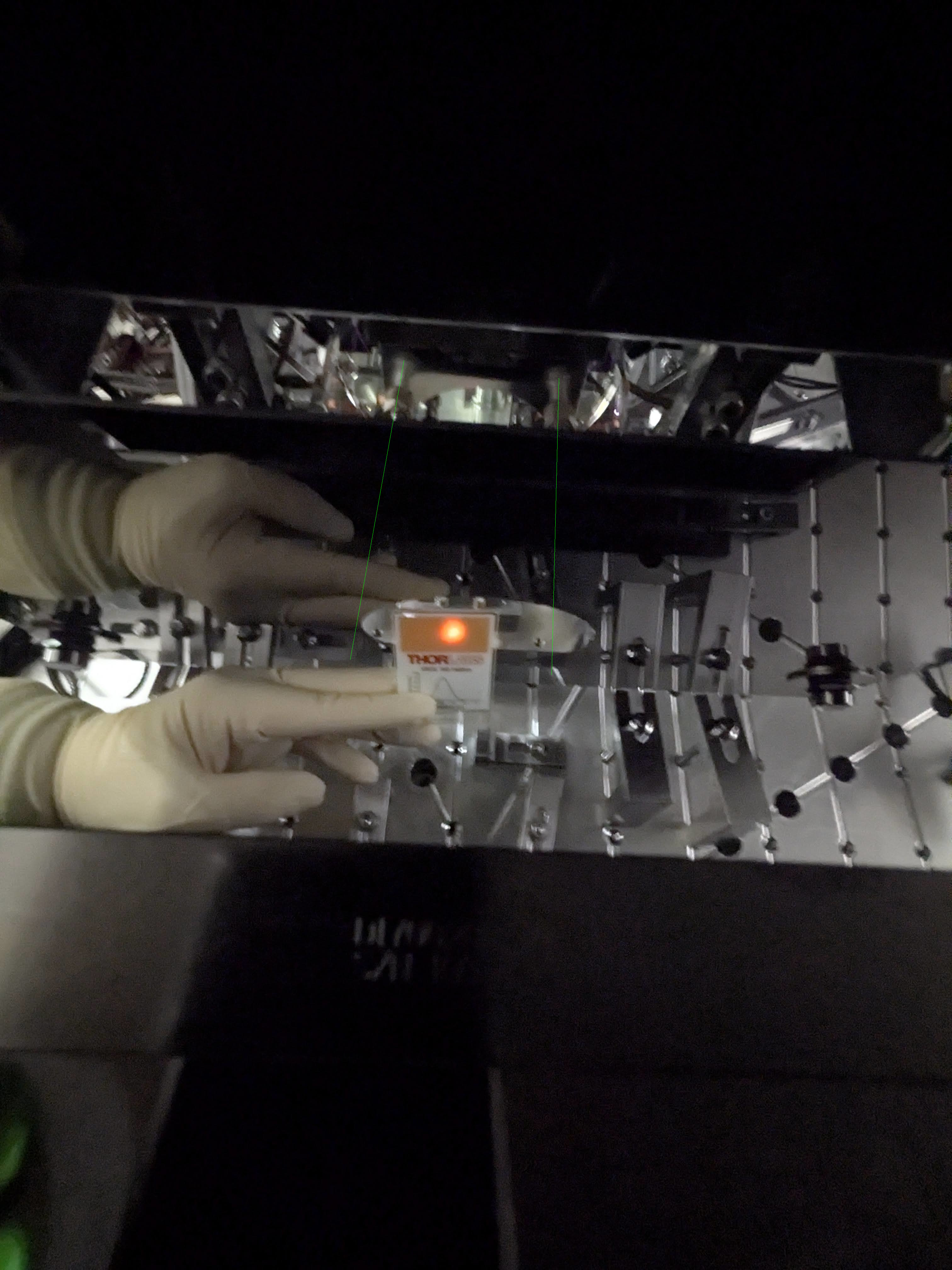
I went to HAM3 to see that the MC2 beam position wasn't crazy. See the first photo, the beam is to the left (+Y direction) relative to the baffle on the HR side but the baffle itself is offset in -Y direction relative to the cage.  Green lines are extension of the EQ stop screws to guide your eyes.

I also opened the ISCT1 and moved the mirror in front of the REFL BBPD out of the way and directed the beam to IFO REFL camera (because I couldn't see the beam at all without moting the mirror).

While manually aligning the IMC, we found that somehow things are in such a bad state that the MC2 TRANS SUM decreases when IM4 TRANS SUM increases, and vice versa. Improving the IMC alignment using IM4 TRANS as well as IFO REFL camera made the flashes stronger to the point that we can see 00 mode once in a while. I was also able to see the beam in the ISS path. But MC2 TRANS was nowhere near centered. Attempts to resolve this by incremental changes failed.

We wondered if something behind MC2 was bumped and changed the alignment into MC2 trans. I looked at the path and didn't see anything obvious. The beam transmitted through MC2 was visible using a card and a viewer, it was not clipped by the baffle behind MC2 nor the BS for the beam dump. I could not see the transmission of the BS, though, it was too weak, so I cannot confirm if the steering mirror in front of the QPD was bumped or not.

Elenna started making big changes for JM3 in PIT (to make big YAW changes in the beam injected into IMC, remember that YAW and PIT are flipped between JAC and IMC, IMC WFS takes care of this but that won't help when you're manually aligning JM3) and moving MC2 and MC1 so that the IMC follows the input beam. Repeating this in YAW anShe successfully centered the beam on MC2 trans. 

At this point I looked at the MC2 beam position again, see the second picture. Apparently the beam moved in YAW by a few mm to the right (i.e. -Y direction).

Elenna will post which optic was moved by how much in which direction.

Jenne is now trying to put IM4_TRANS and ISS QPD beam position back where they used to be using IM2 and 3.

Images attached to this report
Comments related to this report
keita.kawabe@LIGO.ORG - 18:14, Monday 11 May 2026 (90204)

We found that people opening BSC door cover(?) somehow disturbs IMC whether or not HAM3 and HAM2 door covers are on. The IMC fringe becomes super fast and it almost becomes impossible to align anything. Purge air seems to go to strange places to do strange things.

OTOH, when people are out of BSC, we had to put 0.2Hz 150cts excitation to MC2 M1 drive align L2L so the IMC goes across the entire FSR.

elenna.capote@LIGO.ORG - 18:29, Monday 11 May 2026 (90205)

At first, I only moved some combination of MC1, 2 and 3 because we believed that the pointing into the IMC was fine. However, as Keita summarizes above, this was a futile process and veru confusing because it sometimes seemed as if the camera, MC2 trans QPD and IM4 trans QPD all gave differing directions.

However, although Keita said that the beam hit MC2 in a good place, he did clarify this was within mm, so this gave us room to move around JM3 by many microradians. Then, we had this whole realization that JM3 pitch and yaw are flipped relative to IMC pitch and yaw, so some of our other confusion about what we were walking (and why it wasn't really working) started to make sense.

In the end, this is the process that worked: move JM3 a large amount, follow up with MC2 move and some MC1 move in opposite dof (so JM3 pitch goes with MC2/1 yaw). At first, I relied only on IM4 trans, but then the flashes on MC2 trans started to improve, so this became a much more useful signal to follow.
Below, I compare the OSEM readbacks of each suspension from before we started moving to now at the end of the day:

JM3 pitch (IMC yaw): -177 urad

JM3 yaw (IMC pitch): -93 urad

MC1 pitch: -186 urad

MC1 yaw: +83 urad

MC2 pitch: +58 urad

MC2 yaw: -62 urad

MC3 pitch: + 12 urad

MC3 yaw: +21 urad


We should probably put some note next to the JM3 sliders that the pit/yaw dofs are flipped compared to IMC pit/yaw, or I predict that we will recommit this mistake many times over!


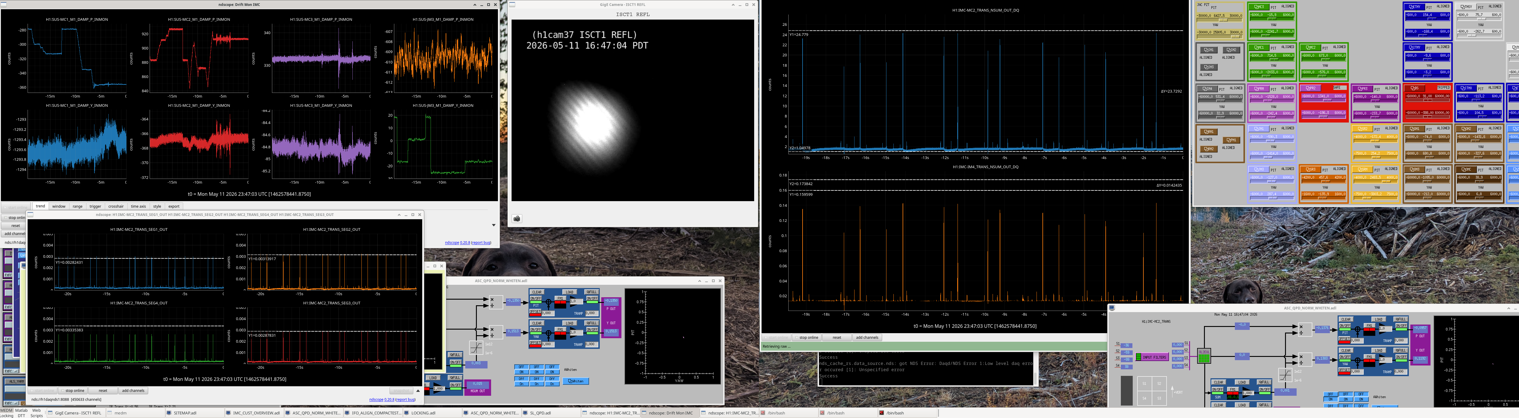
Attached is a screenshot of the IMC aligned in air with associated signals (and dog)

Images attached to this comment
jenne.driggers@LIGO.ORG - 18:39, Monday 11 May 2026 (90206)

Once Elenna had the IMC nicely aligned, we moved on to setting the pointing of the beam headed to the IFO.  We need this to be roughly correct, so that we can use it to align the ISS array.

Back in March when the IMC was locked, Elenna found the locations of the beam on IM4 Trans and ISS QPD:

  • IM4 Trans Pit (March 2026): 0.22
  • IM4 Trans Yaw (March 2026): -0.06
  • ISS QPD Pit (March 2026): -0.92
  • ISS QPD Yaw (March 2026): 0.94

We then worked to move IM2 to get to the right spot on IM4 trans, and then IM3 to get to the spot on the ISS QPD.  The tricky thing is that, since we can't lock the IMC (IOT2 is away from the chamber, so no IMC REFL PD, so no IMC locking), we're just looking at flashes.  So, the spot on the QPDs has to be calculated by looking at peak heights when we get a flash, and doing the matrix math to go from segments to pit and yaw.

.....After 23 different iterations of setting IM2 and IM3 based on an educated guess of where they should go, calculating the QPD spots, finding that we weren't quite right, and then tweaking again, we're leaving the IMs such that we're back to the March location on IM4 trans, but we're less on the edge for the ISS QPD.  Current spots (calculated from the peaks of IMC flashes):

  • IM4 Trans Pit (May 2026): 0.2
  • IM4 Trans Yaw (May 2026): 0.05
  • ISS QPD Pit (May 2026): -0.53
  • ISS QPD Yaw (May 2026): 0.85

This helps assure us that we've got a pretty reasonable beam headed toward the ISS array, and that even if we didn't get the IMC alignment quite right earlier, we should be in a pretty reasonable place and we can use this beam to replace the ISS array.

One final thing we could do as a last check is to calculate the spots on POP A and POP B QPDs (or, at least the one that is used for initial alignment and acquisition), and make sure that we can move IM4 to get to that spot.  That would mean that IM4 trans QPD and POP QPDs are both correct, which sets the pointing of the beam into the PRM and into the IFO, so if that line is correct in air and we use it to align the ISS array, then we will certainly be in a good place when we pump down.  Again, this would just be a check that the IM1+IM2+IM3 position that we've got right now to give us good pointing to the ISS array is compatible with some IM4 pointing to the POP QPD.  The individual segments aren't _DQed, so we'll have to check this tomorrow when the light pipe is open again.

Keita closed the light pipe for the night.

keita.kawabe@LIGO.ORG - 09:19, Tuesday 12 May 2026 (90210)

During the work noted above, I disabled IMC-IM4_TRANS whitening OFF (only one stage was on) because the fringe velocity was big-ish and made flash peaks of some quadrants distorted, which means either the whitening/dewhitening mismatch was a problem (likely) or the ADC was railing (unlikely).

Also, I held the output of H1:IMC-IM4_TRANS_SUM (to avoid dividing P and Y by a tiny number, but of course it was useless). NSUM wasn't changed.

Whitening is still OFF but I turned off the holding of H1:IMC-IM4_TRANS_SUM this morning.

I'll turn one stage of IM4_TRANS whitening back ON after we're done with ISS.

H1 SQZ
sheila.dwyer@LIGO.ORG - posted 17:19, Friday 08 May 2026 - last comment - 16:54, Tuesday 12 May 2026(90186)
looking at SQZ beam profile data from last summer

I had a look at some of the data from Leo Schrader's SURF project, in particular the measured overlaps of the sqz beam with the OMC posted 86485 and the measured q parameters on SQZT7 posted in 86365.  

I first took the measured q parameters, and using finesse propagated them to the OMC and calculated overlaps, which are plotted as sqrt(vertical overlap * horizontal overlap).  The attached scatter plot shows the predicted overlaps compared to the measured overlaps as the ZM4 + ZM5 strain guage voltages vary.  You can see that for the nominal O4 settings of -0.4V ZM5, 6.2V ZM4, the measured q agrees pretty well with the measured overlap.  Moving away from the nominal values, some of the measured qs do not seem very compatible with nearby measured overlaps.  (note, these measurements cover the whole PZT range of 0-200V for both psams, the strain gauges just have different ranges.)

I then tried to use the overlap data to take a gues at what this means for the actuation range of ZM4 + ZM5 psams.  I used the following information from Camille to estimate the ROC of ZM4 and ZM5.  

I used these estimates for optical power with 0V on the PZT and varied a linear slope of optical power per strain guage voltage.  Assuming a slope of mD/V for each psams, I estimated the ROCs of each mirror.  For any set of psams slopes, I estimated the q before ZM4 by using the measured q for the nominal strain guage values of 6.2 and -0.4V. I flipped the sign of the real part and propagated it back to before reflection off ZM4 using the estimated ROCs for that slope, then flipped the sign of the real part again to reverse propagation direction. (Thanks Keita and Disha for help understanding how to flip the qs).  I then propagated that estimated q back through the ZMs allowing the strain gauge voltage to vary and calculated overlap with the OMC.  This approach garantees that the nominal strain gage of 6.2V -0.4V the contour will match the 2.3% mismatch estimated from the measured q there. It would be nice to do an actual fit, and also allow the ROCs at 0V on the PZTs to vary, to see if we can get a better match to the dataset that way.  

In the example contour plot I've put ZM4 at -10mD/V strain gage, which means -0.36mD/V PZT, and the O4 nominal ROC would be -25.6meters.  ZM5 is at -13mD/V strain gage, which means -.47 mD/V pzt and nominal ROC of 2.99 during O4.  

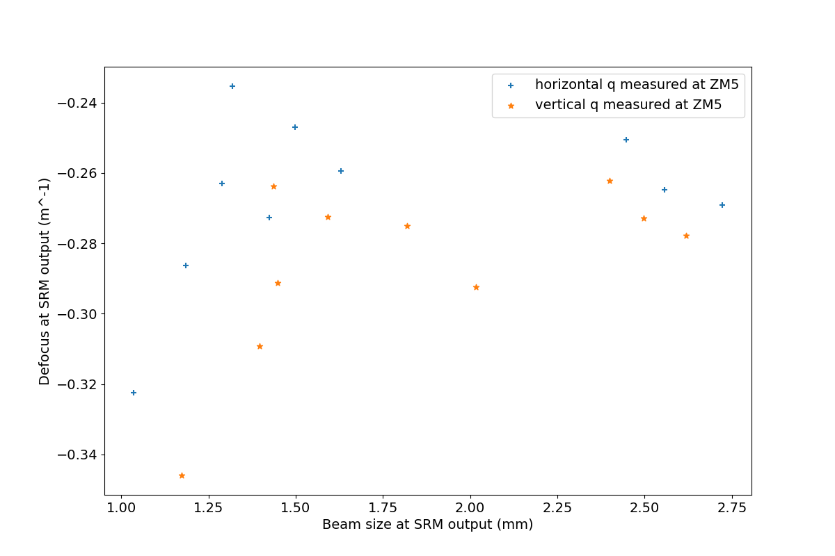
Lastly, I made a plot of propagation of the measured qs to the output of the AR side of SRM, that we can compare to Evan Hall's much nicer plots of SEC and arm cavity modes at SRM.  

The script used to make these plots can be found in the commissoning-modeling-repo here.

Images attached to this report
Comments related to this report
sheila.dwyer@LIGO.ORG - 16:54, Tuesday 12 May 2026 (90218)

Evan and Camille both pointed out that I made an error with the signs in estimating the ROC of the psams after the pre-load change. 

ZM4 has a negative ROC, adding pre-load to ZM4 should make it more curved, having a more negative optical power or a smaller negative ROC. For ZM4 with 0V on PZT, -106 - 2.4*29 = -175.6 mD, or ROC of -11.4 meters. DpV on the strain gage should be a negative number.

ZM5 has a positive ROC, adding more preload should make it less curved, so smaller positive optical power, larger positive ROC. ZM5 before preload change was 667mD, after preload change it should be 667 -2.4*27 = 602mD, or ROC 3.32 meters.  DpV on the strain gage should still be a negative number.  

Correcting this in the script changes the plot of the overlaps slightly, new version is attached.  

ZM4 nominal O4 ROC -9.2m, actuation -0.36mD/Vpzt
ZM5 nominal O4 ROC 3.7m, actuation -0.47 mD/Vpzt

Images attached to this comment
LHO VE (VE)
gerardo.moreno@LIGO.ORG - posted 08:34, Thursday 07 May 2026 - last comment - 19:17, Thursday 28 May 2026(90152)
CP1 Soft Regeneration Update

(Jordan V., Dave B., Gerardo M.)

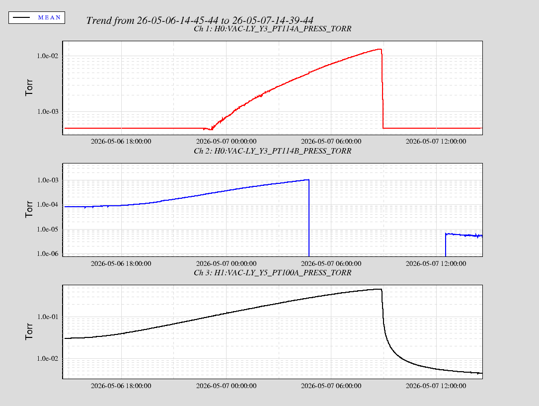
The internal pressure to CP1 turned around overnight signaling that the process of emptying the trap is complete, now we'll continue to monitor and pump on the cryotrap volume.until good pressure is achieved.

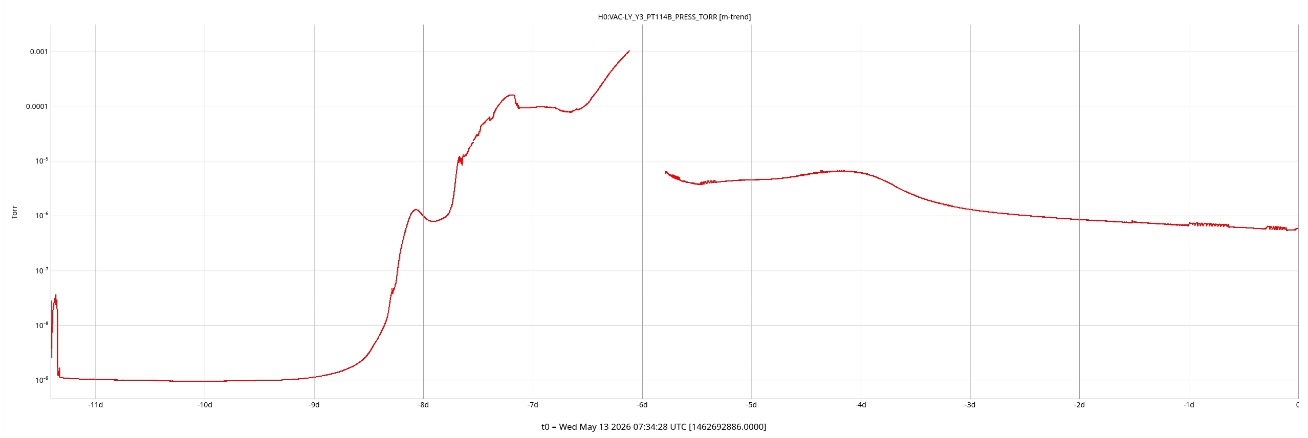
A side note, I manually turned off the CC for PT114B last night at 9:44 pm (local time) as the pressure was rising a bit high, then turned it back on this morning at 5:33 am local time.

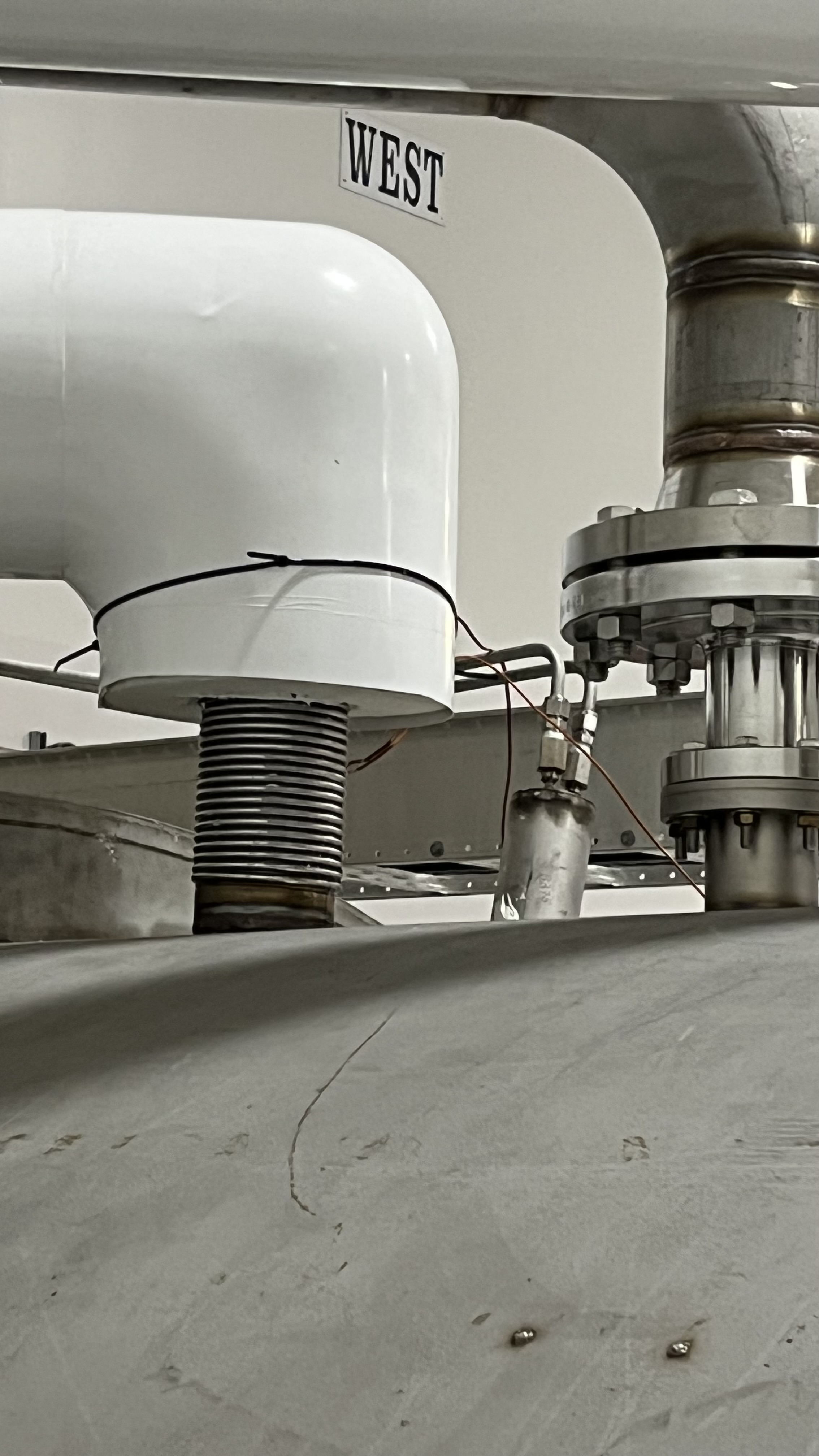
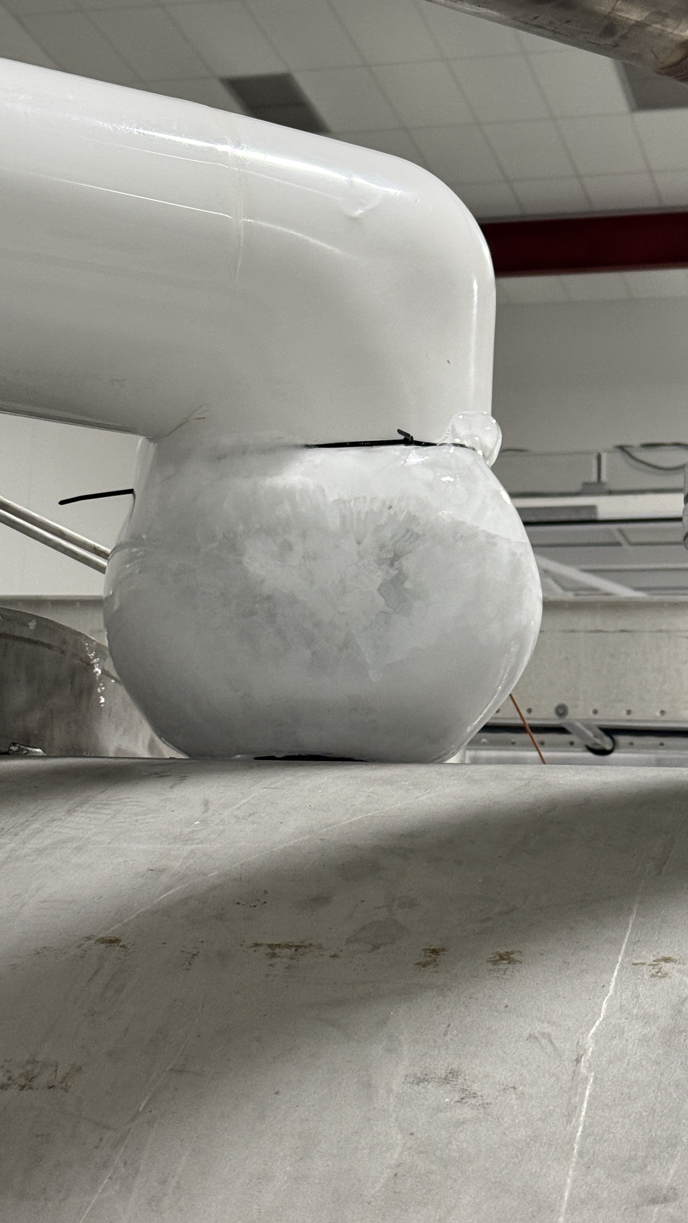
Attached is a snapshot of one day trend data of pressure behavior regarding the soft regeneration for CP1.

Process started here.

Images attached to this report
Non-image files attached to this report
Comments related to this report
gerardo.moreno@LIGO.ORG - 00:44, Wednesday 13 May 2026 (90220)VE

(Jordan, Travis, Gerardo)

CP1 soft regeneration update, CP1 pumpdown continues, system is currently pumped down by the SS500 cart, one turbo pump and one scroll pump.  Yesterday we visited the sensing line and we injected high purity nitrogen gas, we removed the lower sensing line near the Rosemount sensor to be able to inject the nitrogen gas, no issue introducing the gas, lower sensing line appears clear.

To be done, leak check CP1.

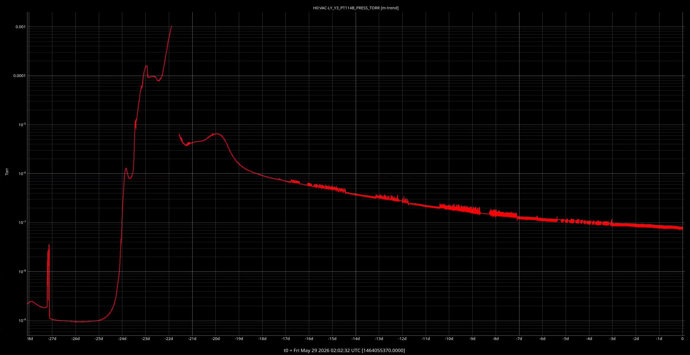
Attached is a plot of the pressure internal to CP1, the plot is for the total ongoing soft regeneration.

Images attached to this comment
gerardo.moreno@LIGO.ORG - 04:03, Thursday 14 May 2026 (90240)VE

(Jordan, Gerardo)

We leak checked CP1, specifically the bi-braze joints, we introduced He to both sensing lines (we disconnected the lines before the 3 way valve -X marks the spot - , this is less disruption to the shape of the metal tubing lines), we started with the bottom or low sensing line, we introduced 1 psi of flow into the line for about 35 seconds, no signal was detected by the leak detector attached to the exhaust of the turbo pump.  We did the same test with the high sensing line, no signal was detected.  Since we had the setup on hand we also decided to spray all the bellows, given that now they are free of ice, sprayed helium for about 35+ seconds, no signal was detected by the leak detector at any of the points sprayed.

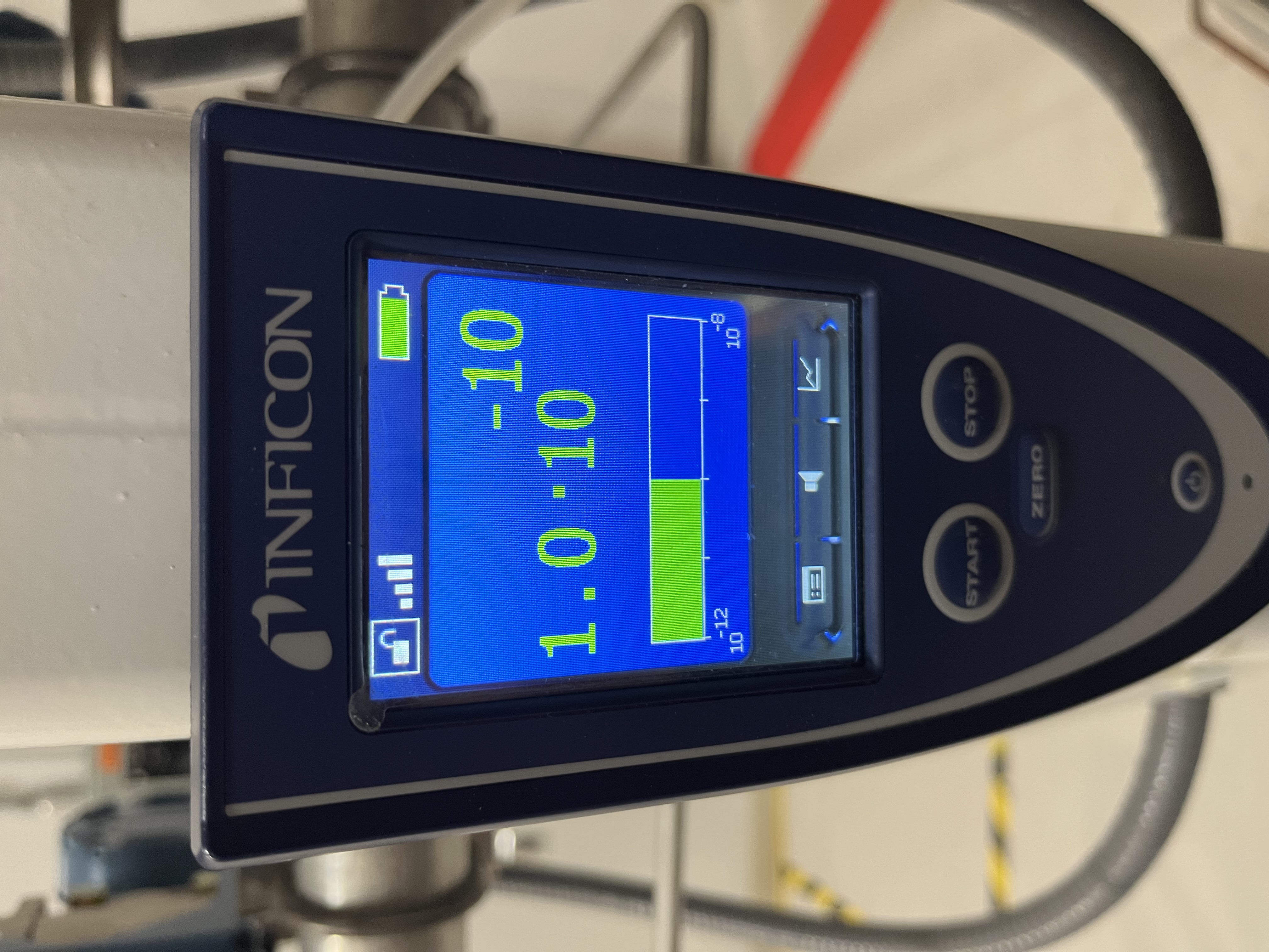
During all the tests performed the He background at the leak detector was 1.0X10⁻¹⁰ Torr*L/Sec.

Images attached to this comment
gerardo.moreno@LIGO.ORG - 19:17, Thursday 28 May 2026 (90376)VE

CP1 pumpdown continues, no issues to report.  However, we had the aux-cart connected to the GV5 annulus trip, but we don't know how it happened, we noted only one tiny slithery critter around the area.

Attached is a plot of the total pumpdown.

Images attached to this comment
H1 SPI (CDS, ISC, SEI, SPI)
jeffrey.kissel@LIGO.ORG - posted 14:50, Wednesday 06 May 2026 - last comment - 11:22, Wednesday 13 May 2026(90139)
First In-vac Components for SPI Pathfinder Installed!! ISI HAM2 (ISIJ) Reflector Assembly Installed and Cabled up to Feedthrus
J. Kissel, J. Warner
ECR: E2400026
WPs: 13237, LHO:13238
Final Design Doc: T2400145
Relevant Systems Level Drawings:
    . Mechanical Assemblies
        :: ISIJ Reflector D2400102
        :: HAM Table Baffles D1700335
        :: HAM2 Systems Layout D0901083 (not yet-inclusive-of-SPI)
    . Electronics Wiring Diagram 
    . Cable Routing In-vac Cable Routing Plan from G2401479 (pages )
    . Flange Layout D1002873-v11

Executive summary:
    - Removed ISIJ +X-side, center, HAM2 ISI table baffle from D1700265-v4 Type 2 
        :: Bracket mounting bolts left screwed into ISI optical table for this will eventually become a D1700265-v4 Type 3 and remounted.
    - Installed ISIJ Reflector + QPD Assembly D2400102 on +X ISI side wall (D071057-v2), with its shroud (D2500030) in place
        :: We didn't weigh it, but the SW Assembly predicts a mass of 1.96 [kg], which we can likely round up to 2.0 [kg] with the shroud installed.
    - Routed and connected QPD read-out cable system to D3 flange, F10 spigot.
    - Routed and connected picomotor cable system to existing D1101515 quadrupus leg Cable #3, J4 
        :: Cable #4, J5 is connected to IO PM5 mirror, Cables #2 J3 and #1 J2 were reset in neat coil with connectors floating to avoid electrical grounding as before.
    - Nudged make-shift baffle system using D1700261 ballast mass baffle mounted vertically on the +X / +Y / Beam Height corner of the chamber wall upon entry into beamtube.
        :: the will DEFINITELY need a technically-minded reset.

In at 10:30a PT and out by 12:30a PT. It's so lovely when everything goes to plan!

Pictures and further info to follow in the comments below.
Images attached to this report
Comments related to this report
jeffrey.kissel@LIGO.ORG - 14:56, Wednesday 06 May 2026 (90140)
Removing Center ISI Table Baffle

Not much to say more here -- removal was easy. We tried "just" removing the panel using the the coated/capped screws, but these didn't budget upon several attempts with Jim's fingers and grunts. So, elected to fight that battle outside the chamber and removed the whole assembly at the table mounting point.

The full assembly is wrapped in dry-wipes, foil, and ameristat bagged and in Mitch's office while it waits for the Type 03 version of the panel to come out of clean-n-bake.
Images attached to this comment
jeffrey.kissel@LIGO.ORG - 15:01, Wednesday 06 May 2026 (90141)
Installation of ISIJ Reflector itself

Also not much to say, other than the great joy that the drawings of the D071057-v2 ISI Side Wall have the irregular positions of the 1/4-20 utility holes accurate enough that Bram's CAD-informed-only mounting holes for the ISIJ reflector's baseplate of the reflector lined up without issue. *phew*

Also -- the D2400102 drawing doesn't highlight which length 1/4-20 bolt should be used for mounting, so we used 1/4"-20 x 0.625"L (5/8"), which was "just enough."

Pictures from the main entry are the best "big picture" views, but here I attach a few more in case the need arises.
Images attached to this comment
jeffrey.kissel@LIGO.ORG - 15:14, Wednesday 06 May 2026 (90142)
QPD Cable Routing

We didn't get dedicated pictures of this QPD cable routing but,
    - it follows the plan on page 22 of In-vac Cable Routing Plan posted to G2401479-v3,
    - You can see the ST1 portion of it well-enough in the above pictures,
    - Jim did the routing, so I trust that there's a healthy loop in the jump from ST1 to ST0, and
    - I attach a picture here of the record that we've connected it to D3-F10, and a copy of the "F-Type" (D2000225-v1) counting from page 18 of the above mentioned cable routing plan.
Images attached to this comment
jeffrey.kissel@LIGO.ORG - 15:19, Wednesday 06 May 2026 (90143)
Picomotor Cable Routing BEFORE INSTALL

Just because we knew little about the details of this cable system ahead of time given how ancient the PM5 picomotor actuated mirror system, I got a lot of good "before" pictures. Mostly, I confirm that PM5 does use the Cable #4 J5 leg of the D1101515 quadrupus, and all the other legs were neatly cable-tied up and away.

 
Images attached to this comment
jeffrey.kissel@LIGO.ORG - 15:27, Wednesday 06 May 2026 (90144)
Picomotor Cable Routing AFTER INSTALL

Here're photos of the routing of the two 72 [in] length D2400316 picomotor extension cables connected in series and routed to all the way around from the ISIJ reflector on the +X face to the -X / +Y corner of the table where CB-9 and the D1101515 quadrupus lives. 

I paid particular attention to the connectors and made sure they were left floating and not shorting to anything metal.

I also re-bundled up Cable #2 J3 and Cable #1 J2 in coil similar to the before pictures, again ensuring that the connectors are floating in both space and electrical connection.
Images attached to this comment
jeffrey.kissel@LIGO.ORG - 15:29, Wednesday 06 May 2026 (90145)INJ, PEM
The Nudged Chamber Wall Baffle

Some pictures of the baffle that we nudged that will likely need re-alignment.
Images attached to this comment
corey.gray@LIGO.ORG - 10:28, Friday 08 May 2026 (90175)EPO

tagging for photos.

jeffrey.kissel@LIGO.ORG - 12:08, Tuesday 12 May 2026 (90212)
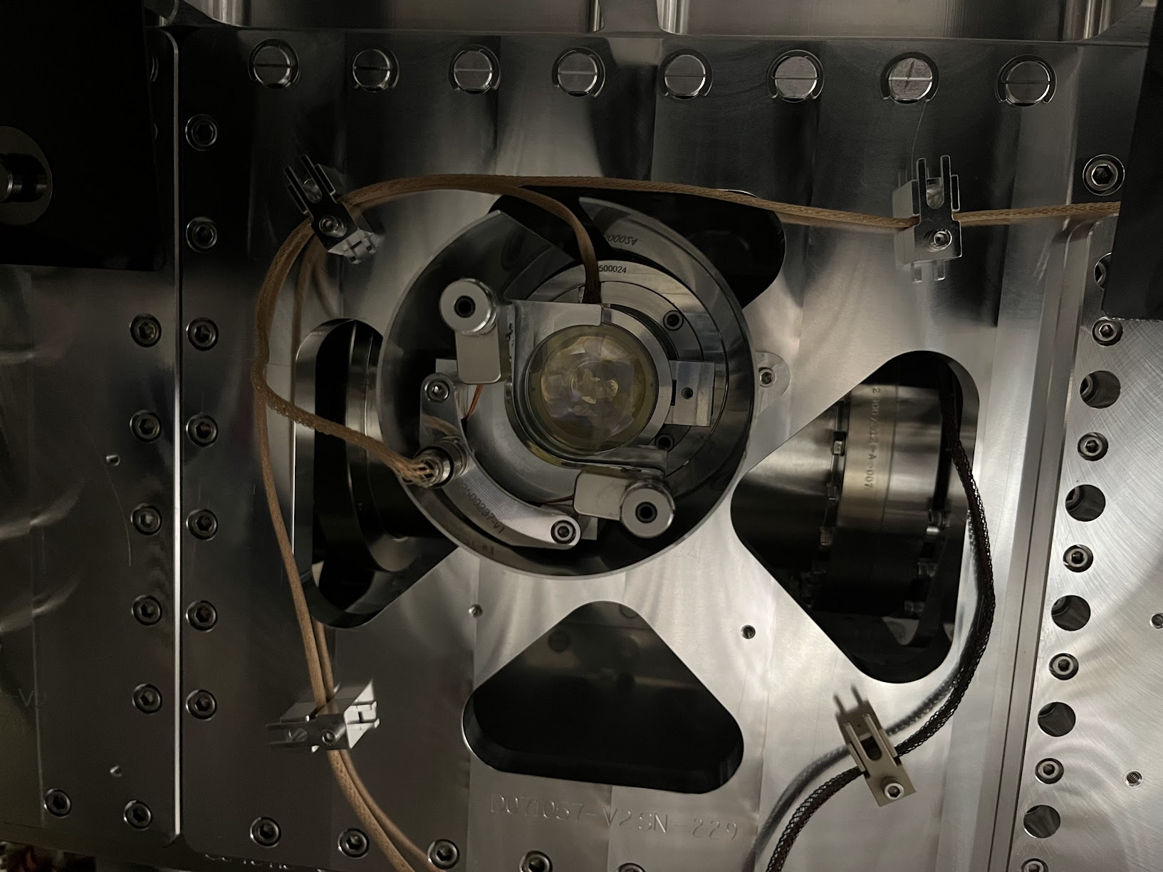
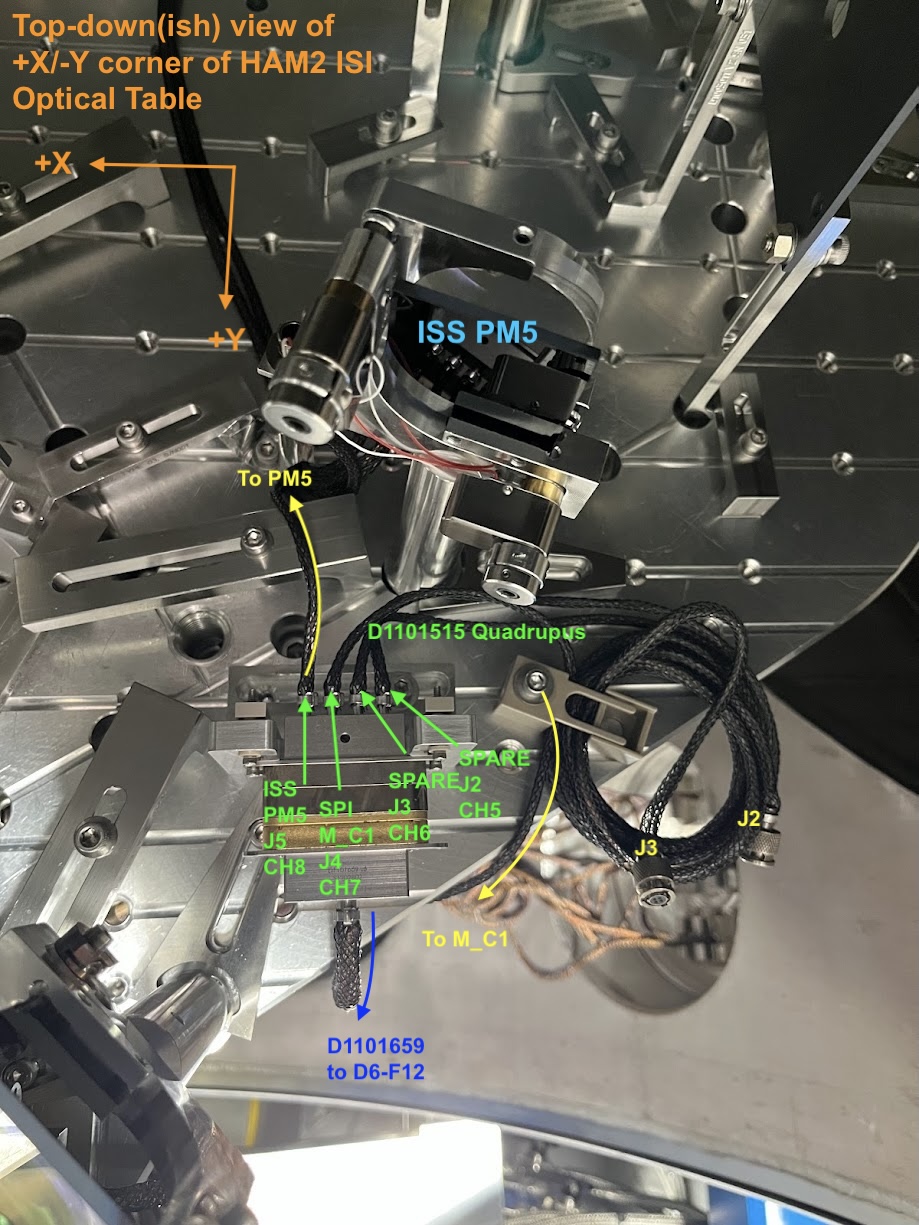
On the new channel assignment of HAM2's SPI ISIJ picomotor, and why I'm confident it's CH7:

Per D1000581-v13, page 13 and then D1900511-v12 page 17, I'm quite confident that the quadrupus cable and up in CH5-8 of the controller on IOT2L, called "PICOMOTOR 5" in D1900511, which I guess becomes "Picomotor B / Slot 2" on page 2 of the ECAT System Diagram D1100683-v11. 

This is corroborated with opening up the picomotor MEDM screen -- sitemap > LSC > picomotors > "HAM 2 + oplev" button (that has "controller 5" and "PICO B" next to it), and clicking through the channels and seeing that CH8 is called "PSL ISS QPD/PD (PM5)."

Here's a labeled picture that makes things more clear.
Images attached to this comment
jeffrey.kissel@LIGO.ORG - 11:22, Wednesday 13 May 2026 (90230)
Belated aLOG on in-vac cable routing of the ISIJ QPD A PD and serial number assignments:

Path       PD Name    PD SN          Monopus            D9-to-D25 Monopus
                      |----------D2600002--------|
                      D1600083 Type 3     D2400340      D2300128
OL ISIJ    QPD A      S2401092            S2500517      S2500511


Images attached to this comment
H1 SUS (SUS)
rahul.kumar@LIGO.ORG - posted 14:01, Thursday 01 February 2024 - last comment - 15:11, Wednesday 01 July 2026(75677)
ZM4 (P-SAMS in HAM7) preload adjusted to change the radius of curvature of the mirror

Camille (CIT), Austin , Rahul

This morning we went to HAM7 chamber and changed the preload on ZM4 (P-SAMS) suspension as per the document E2300463_V1. This changed the RoC of ZM4 mirror without the PZT actuation. Given below are the details of our work - Camille will add pictures later on.

- After setting ZM4 into SAFE state we locked all three stages of the suspension. We had already taken healthy TF measurements before starting our work.

- The bottom mass cable was disconnected and carefully re-routed so that it stays away from the fixture plate.

- four add-on masses (basically 1/4-20 screws with washers) attached to the bottom mass was then removed.

- bottom mass Fixture plate (D2100121) was attached to the structure using six 8-32 screws.

- The bottom mass (already locked using EQ stops) was then further clamped using four 1/4-20 screws through the fixture plate. We had to adjust the height of the bottom mass to the align the threads with the holes on the fixture plate.

- Once the bottom mass was securely clamped, we removed the three set screws on the preloader.

- Using a torque wrench we increased the preload on the bottom mass by ~29 in.lb. (Total preload from torque after increase was 75 in.lb).

- We then followed all the above steps backwards (i.e set screws, add on mass put back, fixture plate removed, cable re-connected and the suspension set free).

- Once all done, we started damping the suspension and checked for any BOSEM flag changes - looked all fine.

- We took the transfer function measurements and ZM4 looked healthy.

Hence we took all the tools out and put the curtains back on HAM7 chamber.

Next, we will go into laser hazard with SQZ team and check for any changes in beam alignment and make adjustments as required.

Comments related to this report
camille.makarem@LIGO.ORG - 14:42, Thursday 01 February 2024 (75679)AWC
1st image: PSAMS locked in place with EQ stops.
2nd image: PSAMS locked with bottom mass fixture plate.
3rd image: Removal of set screws.
4th image: Preload adjustment with torque wrench.
5th image: Preload adjustment with torque wrench.
6th image: Torque wrench dial with the blue needle showing the total torque on the preloader (75 in lbs.)
Images attached to this comment
michael.zucker@LIGO.ORG - 08:21, Friday 02 February 2024 (75692)

Excellent! 

rahul.kumar@LIGO.ORG - 13:41, Friday 02 February 2024 (75710)SQZ, SUS

ZM5 offloaded as well, see LHO alog 75709.

sheila.dwyer@LIGO.ORG - 17:20, Friday 01 May 2026 (90092)

This is ZM4 SN1, so it's original charachterization data (before this preloading) is in E2100289, where with 0 V applied to the PZT the optical power is -106mD (or ROC is -18.877m).  

According to T2300426, changing the preloading changes the optical power by 2.4mD/in.lb.  So, after this preloading the optical power with 0V on the PZT should have been -36mD, or the ROC should be -55.5meters.  

sheila.dwyer@LIGO.ORG - 14:55, Tuesday 12 May 2026 (90213)

Evan and Camille noticed that I flipped a sign here:

The preloading should make the magnitude of the optical power larger, so it should be increased to -106mD - 2.4mD/in lb * 29 in lbs = -175.6 mD with 0 V on the PZT.  ROC = 1/-175.6e-3 = -11.4 meters

camilla.compton@LIGO.ORG - 15:11, Wednesday 01 July 2026 (90860)

In 90859 we've used measurements to find the new ROC. 

Displaying reports 721-740 of 88356.Go to page Start 33 34 35 36 37 38 39 40 41 End