[Alexa and Kiwamu]
As a preparation for the upcoming HAM1 installation work, we applied some modifications on ISCT1. ISCT1 is now ready for the HAM1 in-vacuum work.
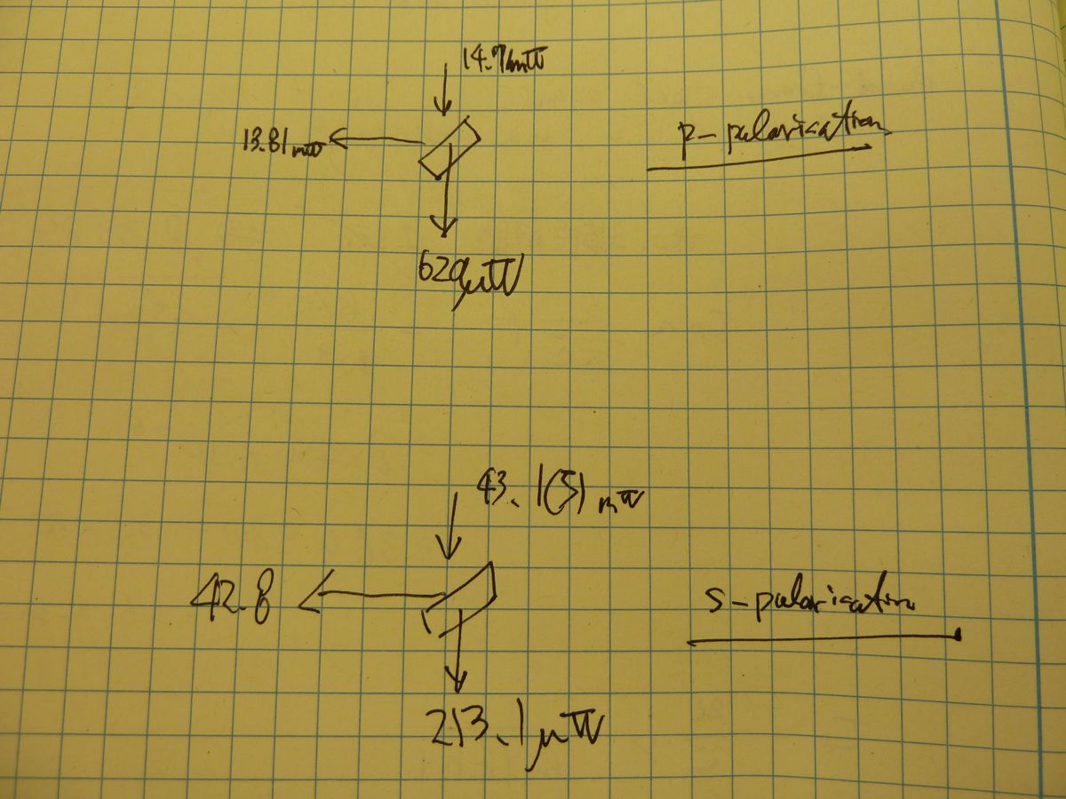
Replacement of a top periscope mirror with a dual-wavelength mirror
We replaced the upper mirror of the middle periscope by a 2" dual-wavelength mirror so that it reflects both 1064 and 532 nm at once. Note that we had three periscopes on ISCT1 (see D1201103-v13 for the diagram) and the one we modified today is the middle one which used to reflect only green light. The mirror we newly put is E1000425-v3 which we took out of the LSB clean room.
Installation of an infrared bottom periscope mirror
We installed a 2" infrared high reflector. This will take care of the PSL doubling infrared light directed by the upper mirror of the middle periscope. Unlike the usual bottom periscope mirror this one simply stands on the optical table instead of being attached on the periscope structure. We stole one of the 2" infrared mirrors from the rightmost periscope and then mounted it for this bottom mirror. Note that we are not going to use the rightmost periscope mirror any more for steering the PSL doubling light and therefore we removed it (see below).
Removal of the rightmost periscope
We removed the rightmost periscope which had been taking care of the PSL doubling light. The periscope is now put nearby the entrance of the squeezer bay.
Removal of a light pipe
We removed the light pipe which was for the lower right viewport of HAM1 since we are not going to use this port any more. The yellow cover and the lexan guillotine were put back to protect the viewport.
Removal of lexan protection plates (a.k.a. guillotines)
During the removal of the rightmost light pipe, we noticed that the rest of two light pipes somehow still had the lexan guillotine in. This is not great because we know the lexan plate does something bad (see for example alog 6073). We are not sure if they had been there all the time during HIFO-Y. We took them out and put the metal cover on the slot because there is no point to keep them in there.
Had been valved-out last week during RGA scanning
On friday, the IO Chassis for SEI was replaced. Second DAC card had offset voltage on some channels without any excitation signals. The offsets were also present with the front end computer off. Tried re-seatting DAC card and even replaced second DAC card, which gave same results.
Attached are plots of dust counts requested from 4 PM September 19 to 4 PM September 20.
I am running conlog-1.0.0 in 'screen' on h1conlog over the weekend as a stability test. The binary is named 'conlog' and is in /ligo/apps/linux-x86_64/conlog-1.0.0/conlog/bin/linux-x86_64. It is currently monitoring 86,948 of the 97,697 process variables listed in /ligo/lho/data/conlog/h1/pvlist_1379718940_no_HPI-PUMP. As of 6:50 PM there are 179,869 rows in the h1conlog.data table.
This morning, from the outside, it appeared to still be running. The EPICS status channels are still there, and the keep alive is updating in the database. However, logging into the server reports that there is 1 zombie process and there are no terminals listed with the 'screen -ls' command.
I've restarted the computer and started it from the local terminal instead of in 'screen'.
Cabling at End X – Corey Work on Seismic Coil Driver at End X –Filiberto Squeezer area Transitioned to Laser Safe status - Alexa Annulus Ion pump work by BSC2 – Kyle Floor repair at End Y - Craftman Getting Baffle parts ready for installation at LVEA – Thomas/Gerardo/G2
Utilized snorkel Genie lift and Main Crane
I've made some changes to the CDS wireless access points, they will now only allow a certain list of known CDS computers to connect (this is in addition to the authentication already in place). If you come across a *CDS* computer that is not working and you think it should be, let me know. In addition, 802.11n data rates are enabled on all of the access points now that all the old OS X installs that caused issues with these data rates have been removed. This should make things a little faster for wireless clients on the network.
Yesterday I was asked by Keita to measure the reflectivity of a beam splitter which will be installed in HAM1 next week. This is called M14 in D1000313. I measured it at the OSB optics lab.
According to my measurement :
R = 99.4 +/- 0.1 % for S-polarizing beam at 1064 nm 45 deg.
R = 94.8 +/- 0.9 % for P-polarizing beam at 1064 nm 45 deg.
Some details :
I used the laser which was already setup for the reference cavity and squeezer experiment in the OSB lab. Conveniently there was a PBS already setup after a Faraday on the table and I used it for specifying the polarization of the beam. I put a pick off high reflector in both the transmitted and reflected sides of the PBS so that I don't destroy the existing setup. Then I directed these beams aside and put the BS that I wanted to measure. The incident angle of the beam should be pretty close to 45 deg with an accuracy of 1 deg or so. This was established by comparing the ray trace with the hole locations on the table. Also I put an ND1 attenuator to reduce the power to less than 100 mW so that my power meter can handle.
I measured the power of both reflected and transmitted light of the BS using the Ophir handy power meter. I assumed that loss is very small.
For S -polarization I obtained the following two numbers (also as shown in the attachment ):
R = 42.8 mW / 43.1 mW = 99.3 % and R = 1 - 213.1 uW / 43.1 mW = 99.5 %.
Therefore a plausible reflectivity can be
R = (99.3 % + 99.5%) / 2 = 99.4 %.
The estimated deviation of this mean value is
sqrt( (99.3 % - 99.4%)^2 + (99.5% - 99.4%)^2 ) / sqrt(2) = 0.1 %.
In summary R at S-pol is 99.4 +/- 0.1 %
I applied the same procedure for P-pol and obtained 94.8 +/- 0.9 %
. This number is close to the specification which is "95 % P-pol".
I have added this result in DCC as a supplimental document. See E1000871-v1.
After some communication with Cheryl, I put away the items left in the staging area of the small cleanroom by HAM1 so that Apollo could move it for next week's entry. There were four bins of items. Cheryl and I will sort through it next week.
The installer came to finish the trim today. He was able to finish the side trim. Unfortunately, he did not bring the trim needed for the end so he'll be back one more time...
Attached are plots of dust counts requested from 4 PM September 18 to 4 PM September 19. Pablo says the spike in counts at dust monitor 8 may be due to the removal of the clean room from over it. This would have been the small clean room between HAM2 and HAM3. I have not been out to check if that is the case.
Still investigating on tilt correction.
I started a measurement for the night. Should be done by tomorrow morning.
*** HPI ***
Undamped
*** ISI ***
750mHz blend on all the DOFs (ST1 & ST2)
Control lvl1 engaged
*** SUS ***
Damped
Jim, Sebastien
We made good progress on the ISI-ETMX testing today. All the sensors have been tested and react properly. Actuator side, we noticed an unwanted ouput voltage coming out of the corner 3 coil driver. We should be able to fix this issue with Richard tomorrow. Except corner 3, all the actuators behave properly.
I've started a set of L2L measurements for corner 1 and 2 tonight. If everything goes well, I'll complete this set tomorrow night.
Tonight measurement should be done by 6am tomorrow morning.
DougC and RickS On Tuesday, we measured the minute trends of the environmental channels over the past week (see attached figure). Ch. 16 is (supposedly) the particle counter in the H1 Diode Room. Either the dust monitor is malfunctioning, or we are having a lot of dust events at the 100,000 count level.
Bugzilla ID 413 has been opened to address this apparent H1 Diode Room dust glitch issue. Attached are two plots, the first the trend of the particle counter (supposedly in the H1 Diode Room) over the past week and the second a detail of one of the glitches.
Did anyone enter the diode room and look at this dust monitor?
I replaced the RAID card in cdsfs1 with a new one. While I had the chassis open, I took the opportunity to vacuum out all the bugs and check the interior cable connections. Even so, upon booting with the new card installed, was greeted by an I2c bus error from the RAID controller. So powered off the server and found a loose connection to the disk backplane, which I either missed earlier or knocked loose when addressing another loose cable earlier (it may also never have been connected properly, once reconnected the RAID controller showed temperature sensors previously not shown on the old controller). On reboot the RAID controller was now happy. But once the server booted the root drive mounted read only due to EXT4 filesystem journal errors. So rebooted once again, which forced a full fsck after which the root filesystem was happy. The RAID controller is now in the process of verifying the RAID; this is a slow process that will take at least a day. So far the system looks healthier, but the RAID verification process should provide a good burn in period.
The RAID verification process was complete when I arrived this morning. I then unmounted the /raid filesystem* so I could force an fsck on it, to verify the integrity of the file structure itself. The fsck passed, so I remounted /raid. It should now be ready to run rsyncs/backups again. I also started the battery backup test on the RAID controller, this takes 'up to 24 hours' to complete. During this time, if the entire system loses power without a clean shutdown, the contents of any data in flight in the RAID cache will be lost; the system is on UPS power so this is a low risk. * I had to modify /etc/exports first to remove /raid, then run exportfs -ra to update NFS; otherwise you get 'filesystem busy' messages. Then the reverse of course when the fsck was finished.
The battery backup test passed with an estimated capacity of 255 hours; so the controller can maintain data in the cache for roughly 10 days without external power. I also checked the controller logs, and so far they are clean with no errors.
(Jeff, Kiwamu, Stefan) With the H1:LSC-REFLAIR_A_RF9_I calibrated in Hz, and the open loop transfer function measured, here is the noise it sees: Input Mode Cleaner transmitted frequency noise. Also plotted is dark noise (shutter closed). We do not know yet what the ugly noise ~1/f^3 noise is.
The loop transfer functions are attached: Open loop gains: CARM_OLG_RED.txt CARM_OLG_GREEN.txt Closed loop gains: CARM_CLG_RED.txt CARM_CLG_GREEN.txt Inverse closed loop gains CARM_iCLG_RED.txt CARM_iCLG_GREEN.txt Inverse closed loop gain with a factor of 1/2 gor Green Hz to Red Hz conversion: CARM_iCLG_RED_g2r_special.txt
S. Ballmer, J. Kissel We had made an estimate for the coil driver noise in low-noise mode (State 3, ACQ off, LP ON), and ruled it out. However, I've checked the state of the Binary IO switches, and MC2 is running in State 2, ACQ ON, LP OFF, and and MC1 and MC3 are running in State 1, ACQ OFF, LP OFF. We'll try for this measurement again, with the coil drivers in their lowest-noise mode.
I've plotted the above-attached, red and green, open loop gain transfer functions (see *_full.pdf attachment). Through trial and error, I figured out that the text file columns are (freq [Hz], magnitude [dB], phase [deg]). And remember these are IN1/IN2 measurements, so it's a measurement of - G, not G (which is why the phase margin is between the data and 0 [deg], not -180 [deg]). Also, because the data points around the UGF were so sparse, I interpolated a 50 point fit around the UGF to get a more precise estimate of the unity crossing and phase margin. See _zoom.pdf for a comparison of the two estimates. I get the following numbers (rounded to the nearest integer) for the raw estimate and the fit estimate: The raw CARM UGF is: 136 [Hz], with a phase margin of: 33 [deg] The Fit CARM UGF is: 146 [Hz], with a phase margin of: 30 [deg] The raw CARM UGF is: 169 [Hz], with a phase margin of: 35 [deg] The Fit CARM UGF is: 170 [Hz], with a phase margin of: 34 [deg]