Displaying reports 75961-75980 of 83434.Go to page Start 3795 3796 3797 3798 3799 3800 3801 3802 3803 End
Reports until 17:19, Tuesday 10 September 2013
LHO General
cheryl.vorvick@LIGO.ORG - posted 17:19, Tuesday 10 September 2013 (7716)
OPS"


Kyle - replace transducer at EX

TMSX measurements lst night

TMSX - Keita and Corey in AM - Betsy, Jeff, Andres in PM - gone now - TF running

BS - alignment in LVEA test stand - some alarms

IMC - Jamie working on Guardian, IMC has drifted out of alignment, WFS won't engage, left off waiting fix

H1 SUS
arnaud.pele@LIGO.ORG - posted 16:14, Tuesday 10 September 2013 (7705)
BS phase 3b M2 TF

After modifying the signs of the gains from the medm, I took a new set of transfer functions of phase 3b (under vacuum) M2 mass of the beamsplitter over the last week end (cf alog 7677 and 7693). During the measurement, the ISI was damped. The plots of the attached document are described below :

- H1 SUS BS M2-M2 undamped transfer functions phase 3b with corrected gain signs (Sept 06th 2013 19:00, in black) compared against H1 SUS BS M2-M2 undamped tf (Sept 06th 2013 15:00, in orange) against the model in blue.

The last measurements are showing a very good match with the model

Non-image files attached to this report
LHO VE
kyle.ryan@LIGO.ORG - posted 16:10, Tuesday 10 September 2013 (7714)
X-end instrument-air "Lead" compressor not running
Will fix tomorrow (after wasp hive relocated)
H1 SEI
vincent.lhuillier@LIGO.ORG - posted 16:03, Tuesday 10 September 2013 (7709)
6.18Hz hunt on ITMY - Source found + Fix in progress

Last Friday, I was mainly searching for the 6.18Hz in the HEPI and ISI actuators/sensors. There was no real conclusion from the study except that the 6.18Hz was not coming from HEPI and it was visible mainly in the vertical degrees of freedoms.

Then, the SUS was suspected. Few tests were done:
- The damping loop and the coil drivers were unplugged. The 6.18Hz didn’t show up in the ISI spectra.
- The coil drivers were re-plugged. The 6.18Hz didn’t show up in the ISI spectra.
- Then, the damping loops were turned on independently. It appears that main chain damping loops using the left and right OSEMs create the vertical motion at 6.18Hz. Then, this motion is transmitted to the ISI and spectra show a 6.18Hz feature.

Two MO OSEM sensor spectra are presented in attachment. In both cases, the ISI is isolated.
- Without SUS Damping (first figure)
- With SUS Damping

J.K and A.P are taking open loop transfer functions.

During the hunt, I saw some excess noise on R0 OSEM RT

Images attached to this report
H1 CDS
david.barker@LIGO.ORG - posted 15:55, Tuesday 10 September 2013 (7710)
Tuesday Maintenance

Added h1iscex channels to the DAQ. 

Stopped h1fw1 writing frames and un-mounted disk system. Dan then replaced both controller cards on the MSR SATABOY RAID. Once the file system was available again, I re-mounted and restarted h1fw1. The data gap on this frame writer is from 11:33 to 13:43 local time. h1fw0 was writing frames the whole time.

Created a new MEDM screen to show GPS diagnostics for the Timing Master unit. It was attached to the SITEMAP via a new SYS related display button. On the next DAQ restart these channels will be added to the frames.

Restarted the h1fe-cds EPICS gateway to see if this sped up the reconnection of MEDM to the Guardian IOCs. It did help somewhat but the reconnection is still slow.

LHO General
bubba.gateley@LIGO.ORG - posted 15:38, Tuesday 10 September 2013 (7708)
Apollo crew
At End X, we relocated the garbing clean room back to the E-module, replaced the curtains and restocked.
Tyler assisted Thomas Vo and Lisa Austin with Ham 4 & 5 baffle assemblies.
H1 AOS
keita.kawabe@LIGO.ORG - posted 14:18, Tuesday 10 September 2013 - last comment - 09:07, Thursday 12 September 2013(7704)
TMSX ISC cable test: Done

We're done with in-vac cable test.

Tomorrow Corey needs to re-rout the cables on ISI back to the intended position (i.e. closer to the real feedthrough).

Comments related to this report
keita.kawabe@LIGO.ORG - 15:35, Tuesday 10 September 2013 (7706)

IR QPDs:

Connected a dirty DB25 cable with a breakout board via dummy feedthrough.

No short circuit, no ground loop.

Used the diode check mode of the DVM to see the continuity of the quadrants, and they are all conductive only from anode to cathode. DVM didn't beep but it showed 500 Ohm-ish number.

Connected a handheld QPD tester and a breakout board, used a strong flash light (Stinger), and the voltage across anode-cathode dropped by about a volt or so when there was a light for all quadrants for both QPD1 and QPD2. Note that the common cathode was biased at +5Volt by the QPD tester, so this was more like the change from 5V to 4V. The drop itself depends on the load impedance of the tester which I don't know and I'm too lazy to look it up. But the basic message is that everything is good.

keita.kawabe@LIGO.ORG - 15:58, Tuesday 10 September 2013 (7711)

Green QPDs:

Diode test mode of DVM didn't work, DVM told that nothing was connected to anything.

The cable section between the ISC table and the feedthrough was exonerated after using this section for the IR QPDs and confirming that IR QPDs looked good.

Swapped the cable back to original configuration, connected the handheld QPD tester, used a flash light, and all quadrants responded to the light correctly. Seems like everything is working.

Disconnected the tester, "measured" the resistance by using DVM though this is in DC and the number the DVM reports doesn't mean much.

In each of the anode-cathode pair in a single QPD, in one direction it was pretty much 1 MOhm and in the other it was about 2 MOhm for both of the two QPDs.

Also, for some cathode pairs in a single QPD, it was about 500kOhm. Doesn't make sense, but I don't know how the DVM sets the voltage and the internal load either.

The green QPDs (Perkin Elmer C30845EH ) are silicon diodes with 8mm diameter while IR QPDs (OSI Q3000) are InGaAs with 3mm diameter. It might be that the photocurrent against ambient light, which is higher in the green ones, was enough to throw off anything done by DVM, or something else is going on that I don't know of.

Bottom line is, the QPD tester result looks good, and probably it's not a good idea to rely on DVM without using the QPD tester. If the handheld tester was the only thing I used (which was the case in EY) I would have said that everything is perfect. 

keita.kawabe@LIGO.ORG - 16:00, Tuesday 10 September 2013 (7712)

Beam diverter:

No short circuit, no ground loop. Reed SWs work. Coil measured to be about 12Ohm.

  "Right" reed SW "Left" reed SW
Beam diverter open open closed
Beam diverter closed closed open
keita.kawabe@LIGO.ORG - 16:04, Tuesday 10 September 2013 (7713)

Picomotors:

Connected the picomotor driver to the air side of the feedthrough via a flipper cable.

Used the picomotor test interface to manually control each picomotor.

Everything worked.

The only thing to remember is, "motor 1" of the controller is connected to the picomotor labeled "D",  2 to C, 3 to B and 4 to A. I'll wait until Sheila comes back next week to see how things were wired in Beckhoff world at EY.

corey.gray@LIGO.ORG - 09:07, Thursday 12 September 2013 (7739)

Ok, I just noticed Keita added all of these sub-entries.  But I just made a picture of the oddity with labeling of the Picomotor cable & Driver assignment.  Oh, and it's also useful to know where each picomotor is where on the Table.  Anyways, it's attached.

Images attached to this comment
H1 FMP
jodi.fauver@LIGO.ORG - posted 13:17, Tuesday 10 September 2013 (7703)
Y End Flooring
I spoke to the folks at Craftsman today. The trim pieces have been ordered and are due in next Tuesday, 17 September. Installation is scheduled for that day as well.
H1 SUS
arnaud.pele@LIGO.ORG - posted 12:33, Tuesday 10 September 2013 (7700)
ITMX TF

Transfer functions of the ITMX at the test-stand have been running overnight yesterday, after last alignement. The attached plots are showing :

(1) M0-M0 undamped transfer functions for the 6 dofs, compared against  "wire rehang" model

(2) R0-R0 undamped transfer functions for the 6 dofs, compared against "thincp" model

Main chain was showing source of rubbing (all dofs of first attachement, except yaw). It turned out that during those measurements, an EQ stop was touching the top of the M0 test mass (main chain). It has been pulled back this morning. Reaction chain looks similar to the model, except for pitch, which we assume

(3) Spectra of ITMX in euler basis for main and reaction chain :

-after alignement of main chain, reaction chain not aligned (blue curve Sept 04th )

-after alignement of main and reaction chain, EQ stop touching the test mass (green curve Sept 10th)

-after alignement of main and reaction chain, after pulling back the EQ stop (red curve Sept 10th)

Looking at the vertical dof of main chain for eg, page 9, we can see that the frequency of the first mode of vertical (0.55Hz) reappeared after the EQ has been moved. 

Data, script and result files will be commited on the svn after this entry.

Transfer functions for ITMX will be running again overnight

Non-image files attached to this report
H1 SEI
filiberto.clara@LIGO.ORG - posted 12:18, Tuesday 10 September 2013 (7702)
ITMY SUS ISI
ITMY Coil driver outputs were disconnected from field satellite units to help Vincent with 6.18Hz noise search at noon. See alog:
https://alog.ligo-wa.caltech.edu/aLOG/index.php?callRep=7609
LHO VE
kyle.ryan@LIGO.ORG - posted 12:10, Tuesday 10 September 2013 (7701)
Replaced instrument-air transducer @ X-end


LHO General
patrick.thomas@LIGO.ORG - posted 11:38, Tuesday 10 September 2013 (7698)
Ops Summary (morning)
Dave B. added h1iscex model to the DAQ, DAQ restart
10:26 Dave B. restarted the EPICS gateway between the ops and fe LANs to diagnose the guardian software.
11:07 Cyrus R. changed HVE-EX:INSTAIR_PT599.LOW to 55
11:33 Dave B. restarting fw1 for disk repair
H1 AOS
jason.oberling@LIGO.ORG - posted 11:26, Tuesday 10 September 2013 (7699)
ITMx Cartridge Alignment
IAS: J. Oberling
SUS: B. Weaver, T. Sadecki
 
Over the last couple days we've been fighting the CPx alignment.  This was "finalized" yesterday until Arnaud's transfer functions showed main chain rubbing (reaction chain good).  Travis found and corrected the rubbing this morning and I took another set of pitch/yaw measuremnts of the ITMx to confirm we are still good.  We are.  The position errors remain unchanged from alog 7638.  Pitch/yaw errors and ITMx/CPx gap are as follows:

To be on the safe side, I left the IAS equipment set up at the test stand until we get a good set of transfer funtions.

LHO VE
cyrus.reed@LIGO.ORG - posted 11:06, Tuesday 10 September 2013 (7697)
Updated h0veex instrument air alarm settings
I've updated the low level alarm level settings on h0veex at the request of Patrick/Kyle for channel HVE-EX:INSTAIR_PT599.  The old value was '59', the new value is '55' for 'HVE-EX:INSTAIR_PT599.LOW'.  The DB file has been modified on vxboot to preserve this setting across VME boots, in addition to changing the current value via caput.
H1 SUS
arnaud.pele@LIGO.ORG - posted 08:47, Tuesday 10 September 2013 (7696)
TMSX

TMSX transfer functions are showing a bad coherence (see the attached snapshot of the dtt session for the pitch to pitch transfer function). Excitation was uniform white noise of amplitude 2500 from 0 to 50Hz, with a 0.01Hz bandwidth for Pitch

I told Corey and Keita to go ahead for cable testing, I will try new settings when they will be done.

Non-image files attached to this report
H1 ISC
alexan.staley@LIGO.ORG - posted 20:48, Monday 09 September 2013 (7695)
ISCTEY information

(Kiwamu, Alexa)


 With the ISCTEY Prometheus laser set as follows,

PPKTP Crystal @ 32.27 C

NPRO Crystal @ 24.00 C

Diode A @ 23.00 C

Diode B @ 21.00 C

we measured the Current (A) vs Power(W) out of the laser aperature for the 1064nm beam (see pdf file).


We found the optimal configuration for the laser to be,

PPKTP Crystal @ 33.81 C

NPRO Crystal @ 24.00 C

Diode A @ 23.00 C

Diode B @ 21.00 C

Current 1.503A

such that at the aperature, the power of each beam was,

1064nm: 1.371W

532nm: 40.1mW


In this optimal configuration, we measured the power after the quarter-wave plate (QWP), half-wave plate (HWP), and Faraday Isolator (FI) for the 1064nm beam, and found it to be 1.282W. Thus, we deduced that the throughput of the FI was about 93%. Then we proceeded to examine the beam profile with the nanoscan.

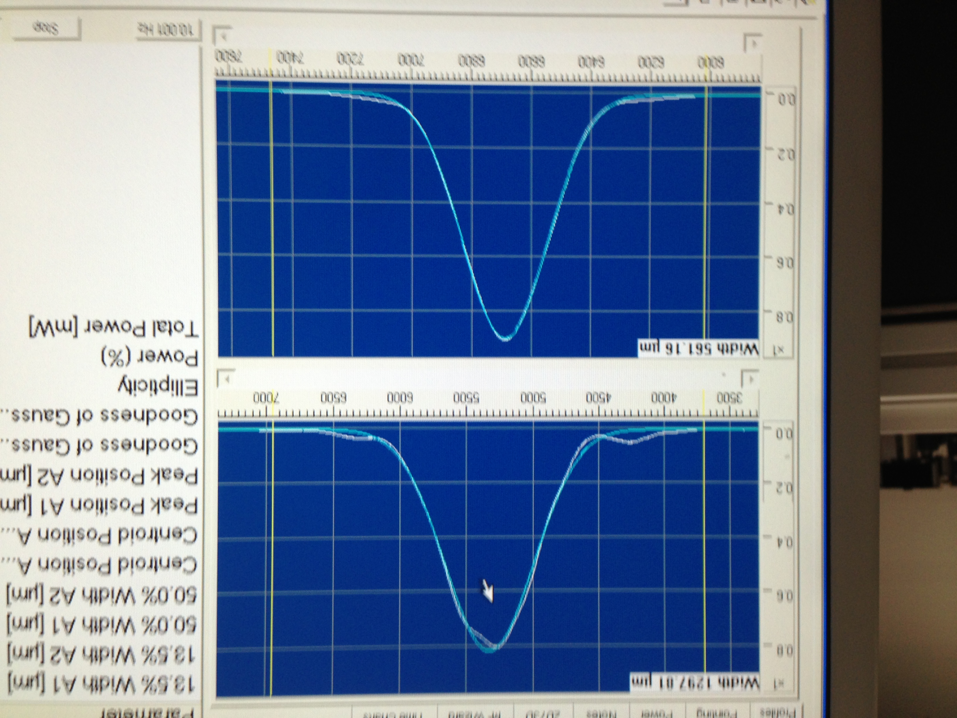
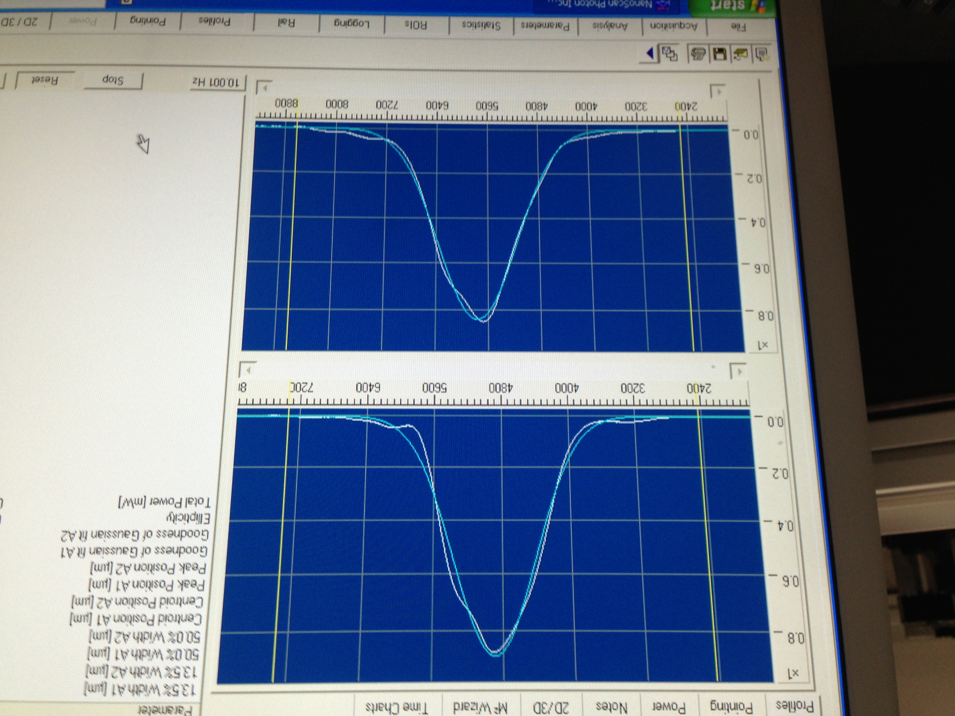
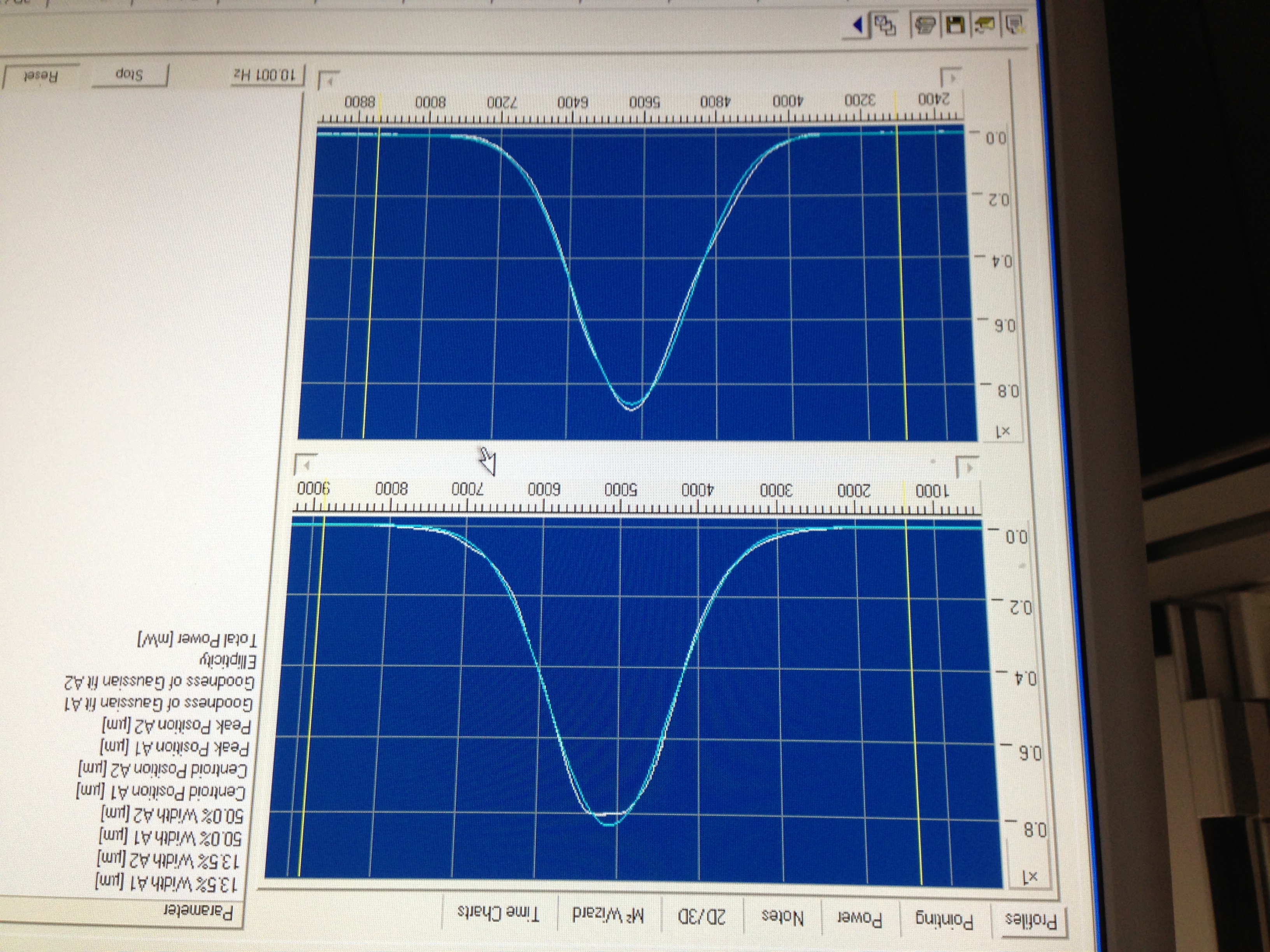
The first picture (1064nmNoFI.pdf) shows the beam profile immediatly following the aperature of the laser.

The second picture (1064nmFILowCurrent.pdf) shows the beam profile after the FI with the current set to 0.803A (about 10mW of power)

The third picture (1064nmFIFullCurrent.pdf) shows the beam profile after the FI with the current set to 1.503A (about 100mW of power)

In these images, the top graph is of the horizontal profile and the lower graph is of the vertical profile. Immediatly after the laser aperature, we see a nice gaussian profile for the vertical profile. As expected, the horizontal profile does not fit a guassian as nicely. After the FI, the vertical profile deviates from the guassian shape. We attempted to adjust the FI alignment in order to improve this profile; however, it only worsened the profile. (Tomorrow I will collect raw data of the beam profiling after the FI).


(Note: See D1100607-v13 for table layout as a reference)

(Note: Temporary shin was placed below FI to obtain 4in required height)

Images attached to this report
Non-image files attached to this report
Displaying reports 75961-75980 of 83434.Go to page Start 3795 3796 3797 3798 3799 3800 3801 3802 3803 End