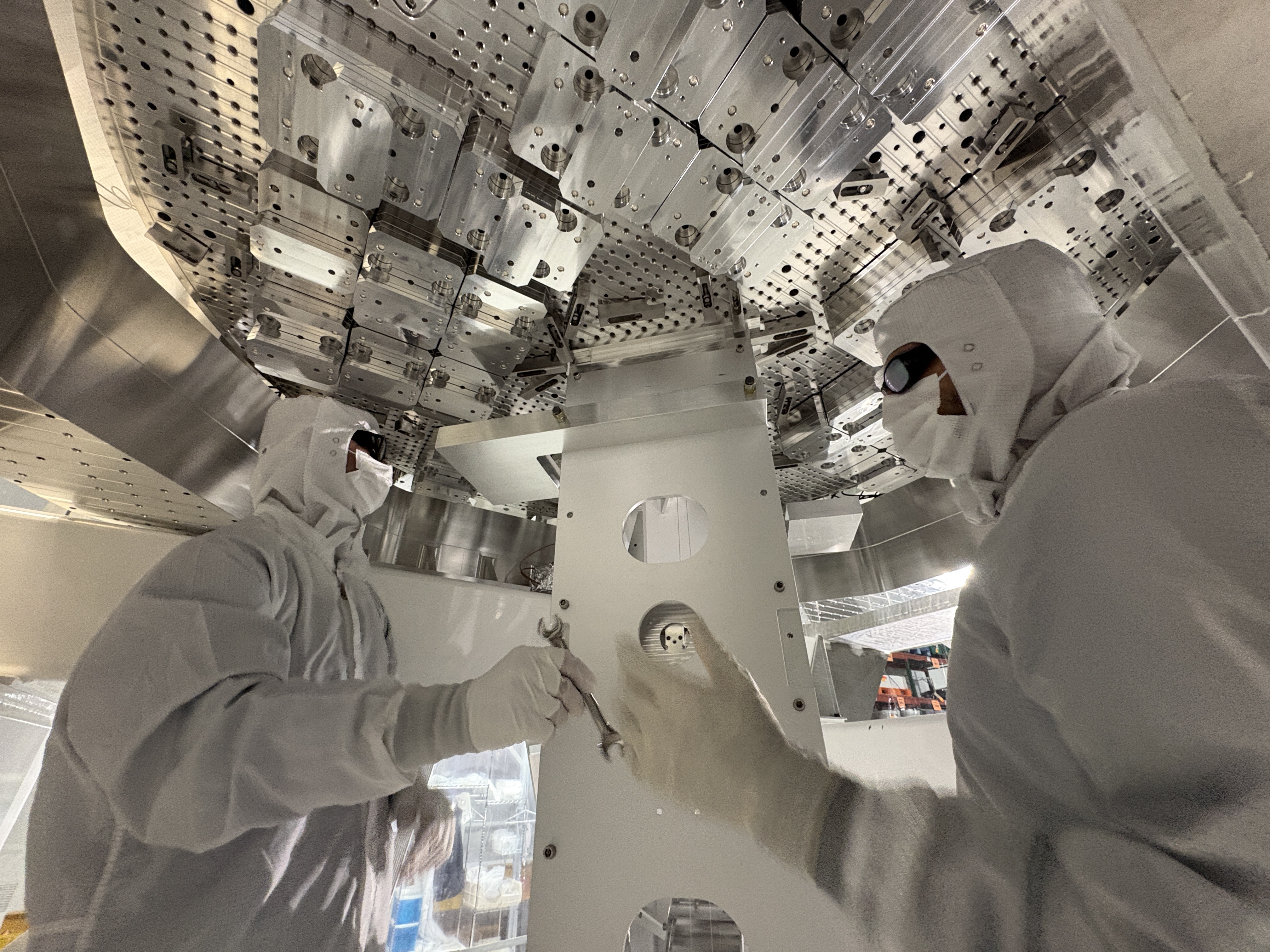
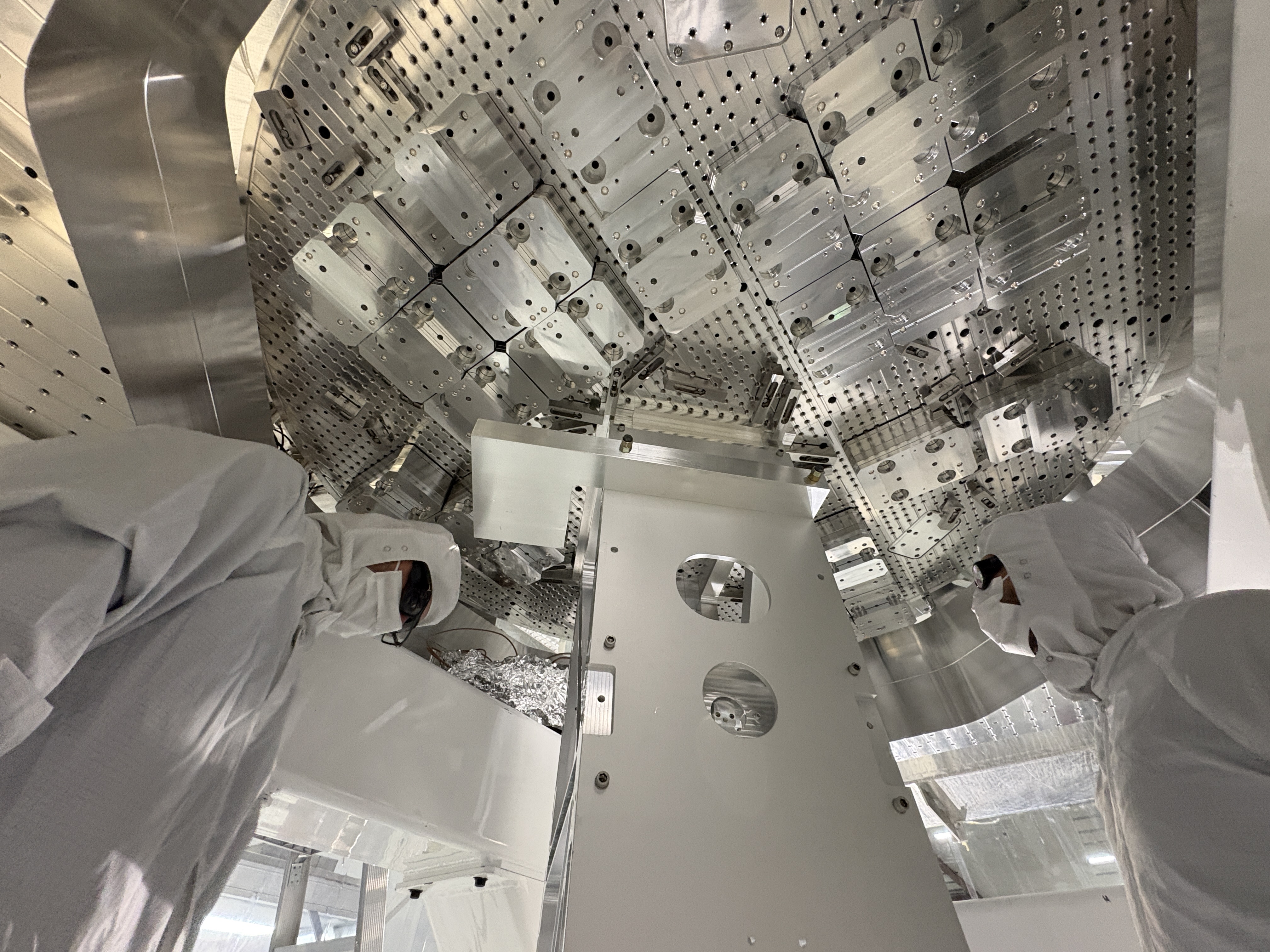
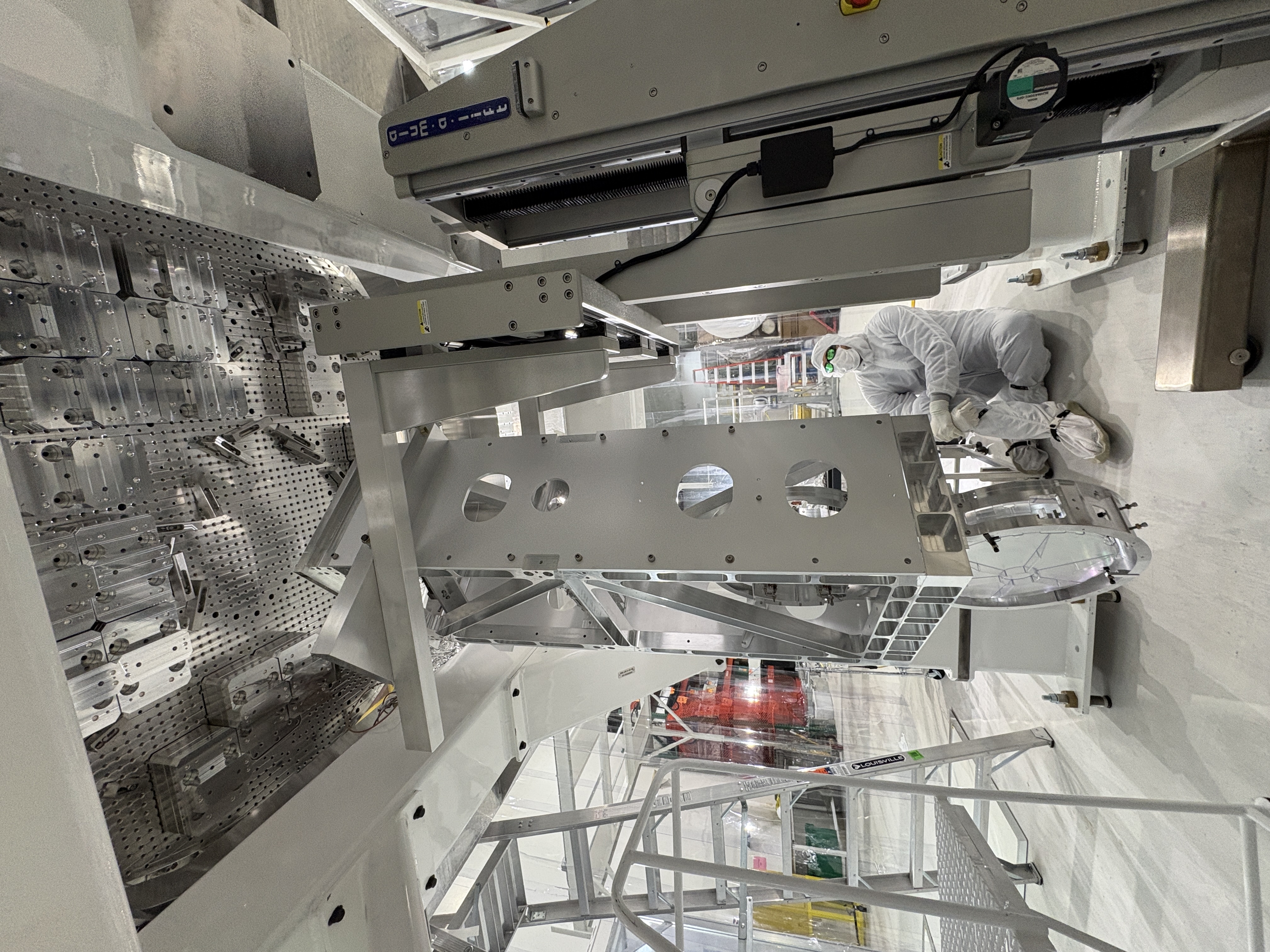
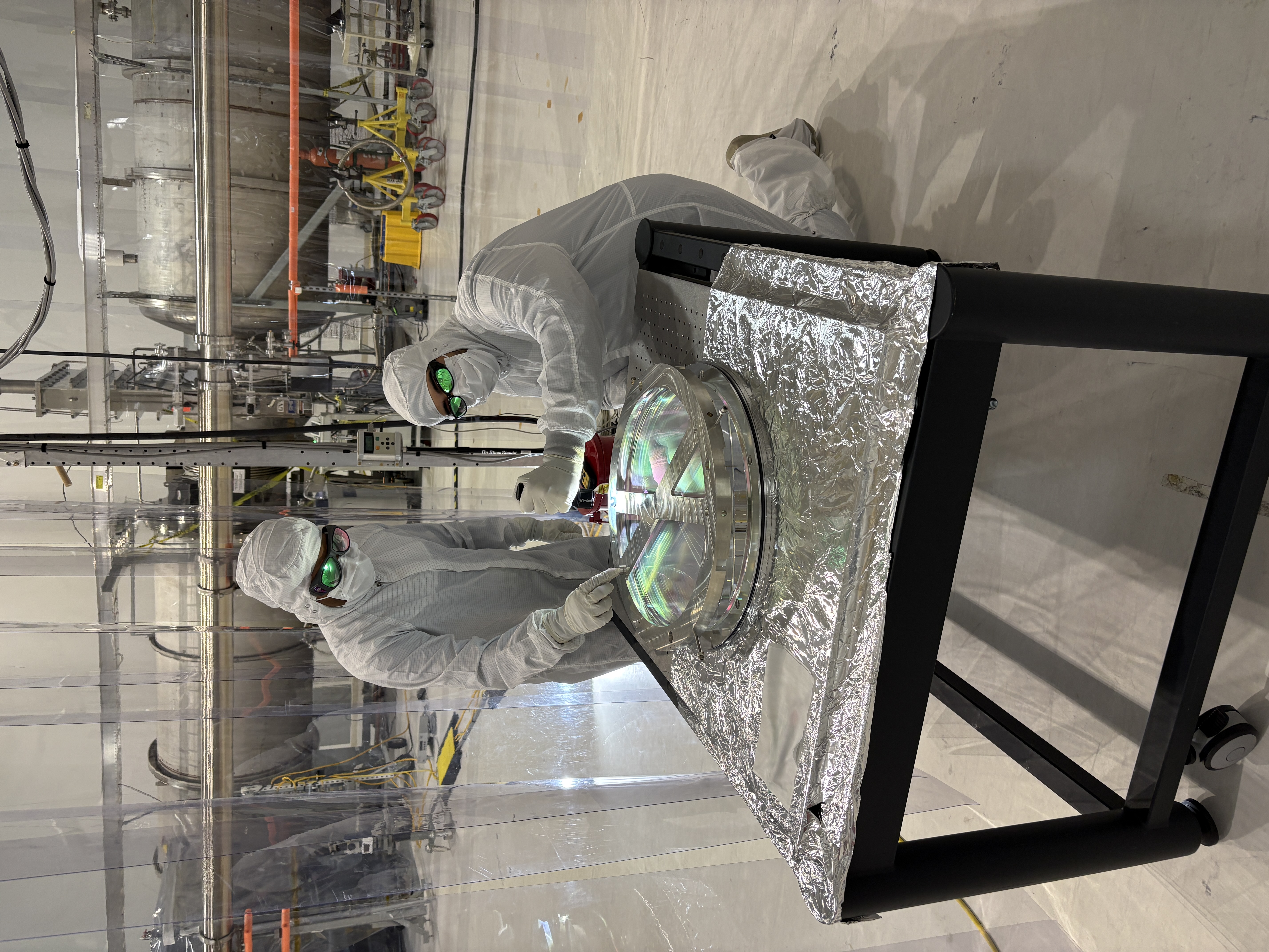
Ibrahim, Randy, Betsy, Rahul
Today, we:
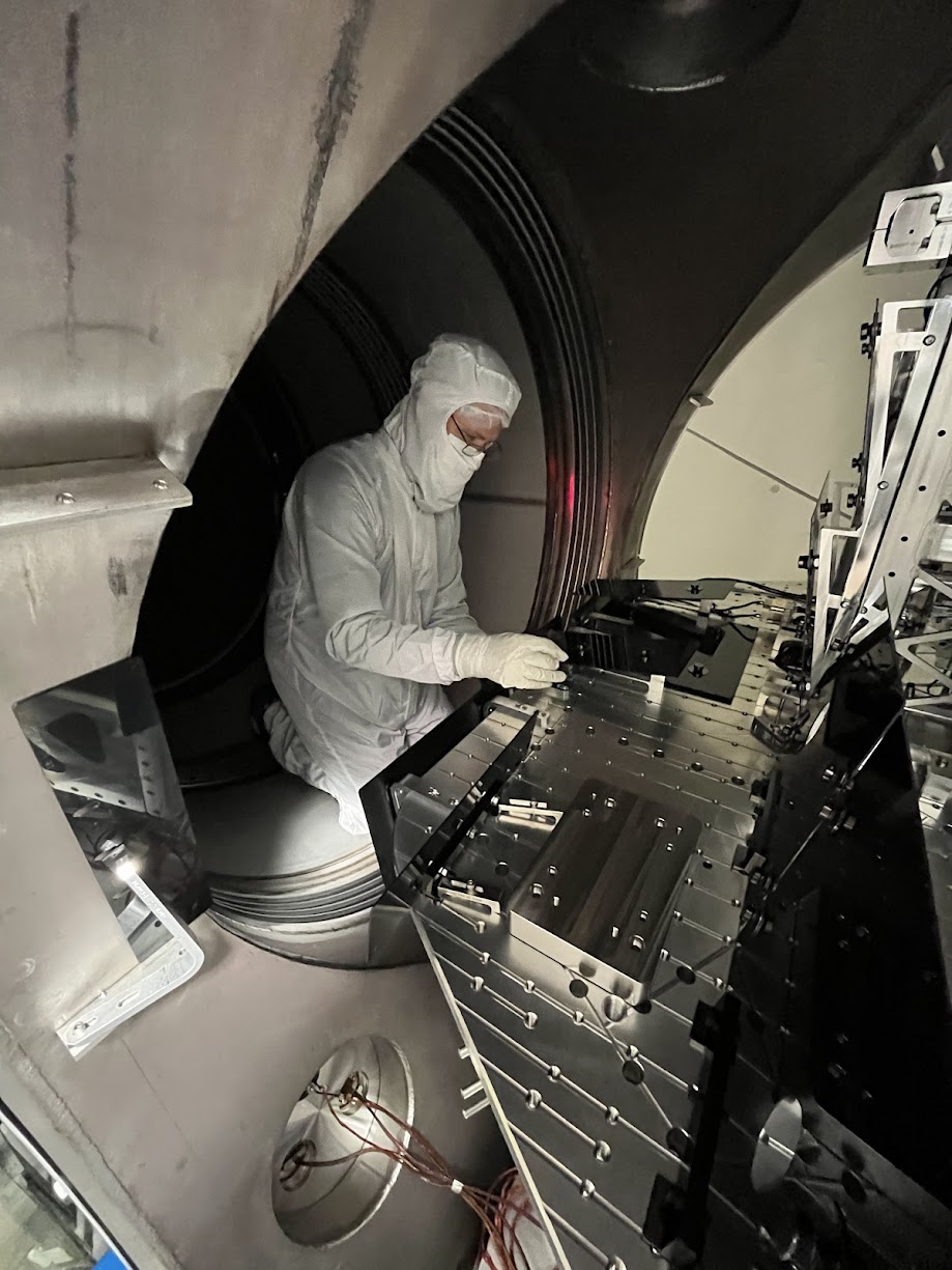
See pictures
I've gone through and filled in most of the infrastructure for the BBSS (found under BS/ITM on sitemap as BBSS temp). Values and filter settings have been saved to sdf and filters added have been committed in H1SUSLO12.txt as r35219. For the majority of the filters banks, I turned any filters that are shown as being on in whatever I referenced them from, but all filter banks have INP and/or OUT OFF, so no signal can pass through.
Infrastucture filled in:
All stages
OSEM2EUL / SENSALIGN / EUL2OSEM Matrices
Filled out according to matrices calculated in /ligo/svncommon/SusSVN/sus/trunk/BBSS/Common/MatlabTools/make_susbbss_projections.m. The Y direction matrix elements for M1 OSEM2EUL have been left blank for now
M1
OSEMINF Filter Banks
- _{F1,F2,F3,LF,RT,SD}_{X_RAW,Y_RAW,SUM} have satamp compensation filter of zpk([0.145],[720e-6],1) installed in FM1, called 0.15:7e-4
- _{F1,F2,F3,LF,RT,SD}_{X,Y} have a conversion from counts to um with a gain(250) in FM5, called to_um. This value was found by using the conversion from Tom of 4000 counts / meter, and then converting meters to um.
- Tom said that we will not need any offsets, and the QOSEMs are calibrated so we don't need any special gains in the filter banks, so I've set the filter banks to gains of 1.
WATCHDOG Filters
BANDLIM Filter Banks
- Same filters as in OSEMINF, plus acBandLimiter
RMSLP Filter Banks
- 10 second LP added into FM1
LOCK Filter Banks
- Copied over from BSFM M1 for now
DAMP Filter Banks
- Copied the damping filters from BSFM M1 over for now
COILOUTF Filter Banks
- Copied over from BSFM M1 for now
M2
OSEMINF Filter Banks
- Satamp precise compensation filters inserted into FM1 according to the installed satamp for M2, plus conversion to_um in FM5
- Offsets and gains need to be re-done for BBSS M2
WATCHDOG Filters
BANDLIM Filter Banks
- Same filters as in OSEMINF, plus acBandLimiter
RMSLP Filter Bank
- 10 second LP added into FM1
LOCK Filter Banks
- Copied over from BSFM M2 for now
OLDAMP Filter Banks
- Copied over from BSFM M2 for now
VRDAMP Filter Banks
- Copied over from BSFM M2 for now
COILOUTF Filter Banks
- Copied over from BSFM M2 for now
M3
OSEMINF Filter Banks
- Satamp precise compensation filters inserted into FM1 according to the installed satamp for M3, plus conversion to_um in FM5
- Offsets and gains need to be done for BBSS M3
WATCHDOG Filters
BANDLIM Filter Banks
- Same filters as in OSEMINF, plus acBandLimiter
RMSLP Filter Bank
- 10 second LP added into FM1
OPLEVINF Filter Banks
- Copied over from BSFM M3 for now
LOCK Filter Banks
- Copied over from BSFM M3 for now
COILOUTF Filter Banks
- Copied over from PR3 M3 since they have the same electronics for M3
TITLE: 05/12 Day Shift: 1430-2330 UTC (0730-1630 PST), all times posted in UTC
STATE of H1: Planned Engineering
CURRENT ENVIRONMENT:
SEI_ENV state: MAINTENANCE
Wind: 4mph Gusts, 1mph 3min avg
Primary useism: 0.01 μm/s
Secondary useism: 0.09 μm/s
QUICK SUMMARY: IPC errors on h1susMC2 and h1seiproc, dackill on h1iopseib2. All sus aligned and damped except PR2 which is in safe (looking into this), SEI in state captured by the whiteboard. Temps look good and dust counts look good in the LVEA. More laser hazard work planned for the day in the LVEA.
Workstations were updated and rebooted. This was an OS packages update. Conda packages were not updated.
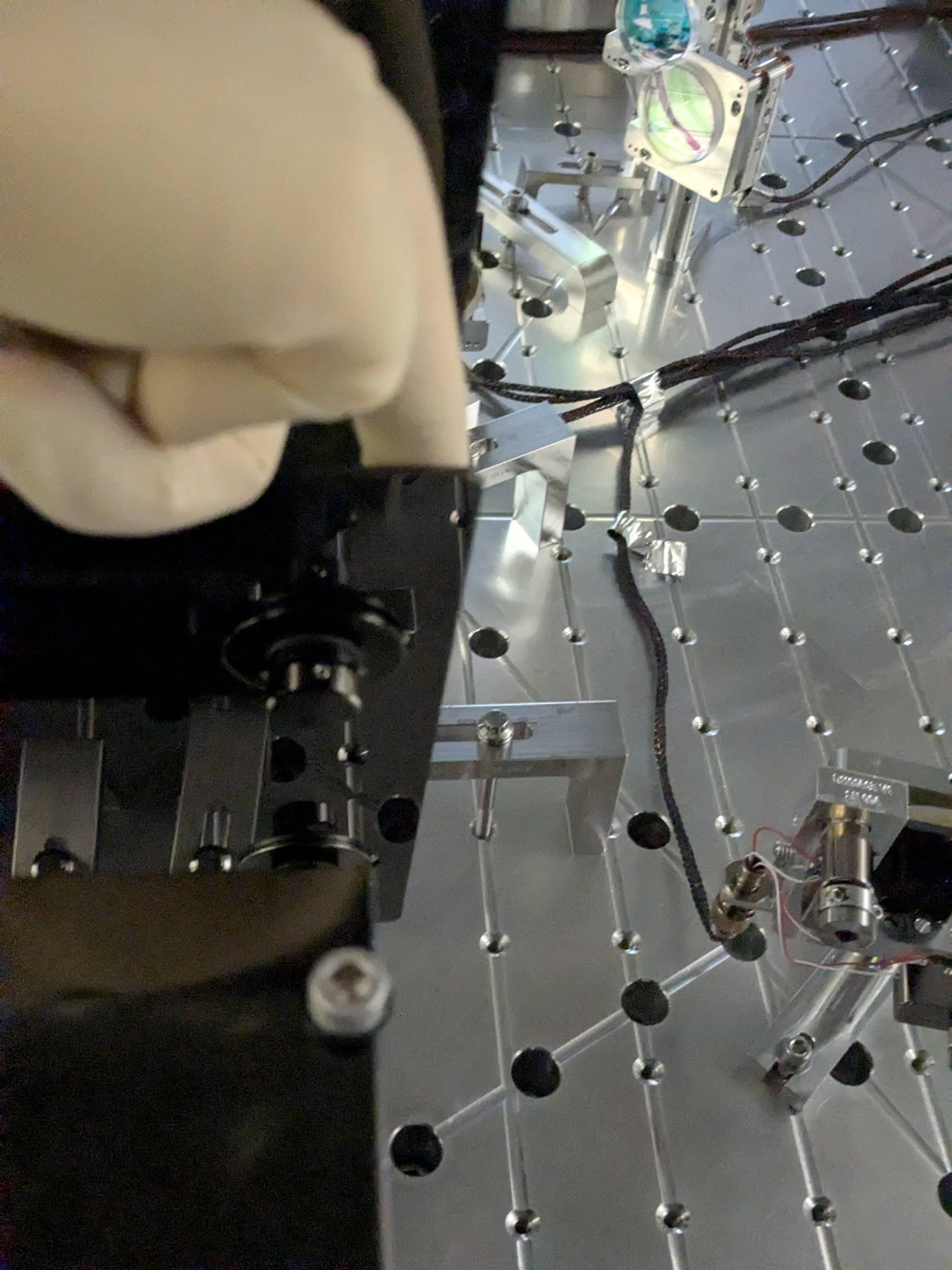
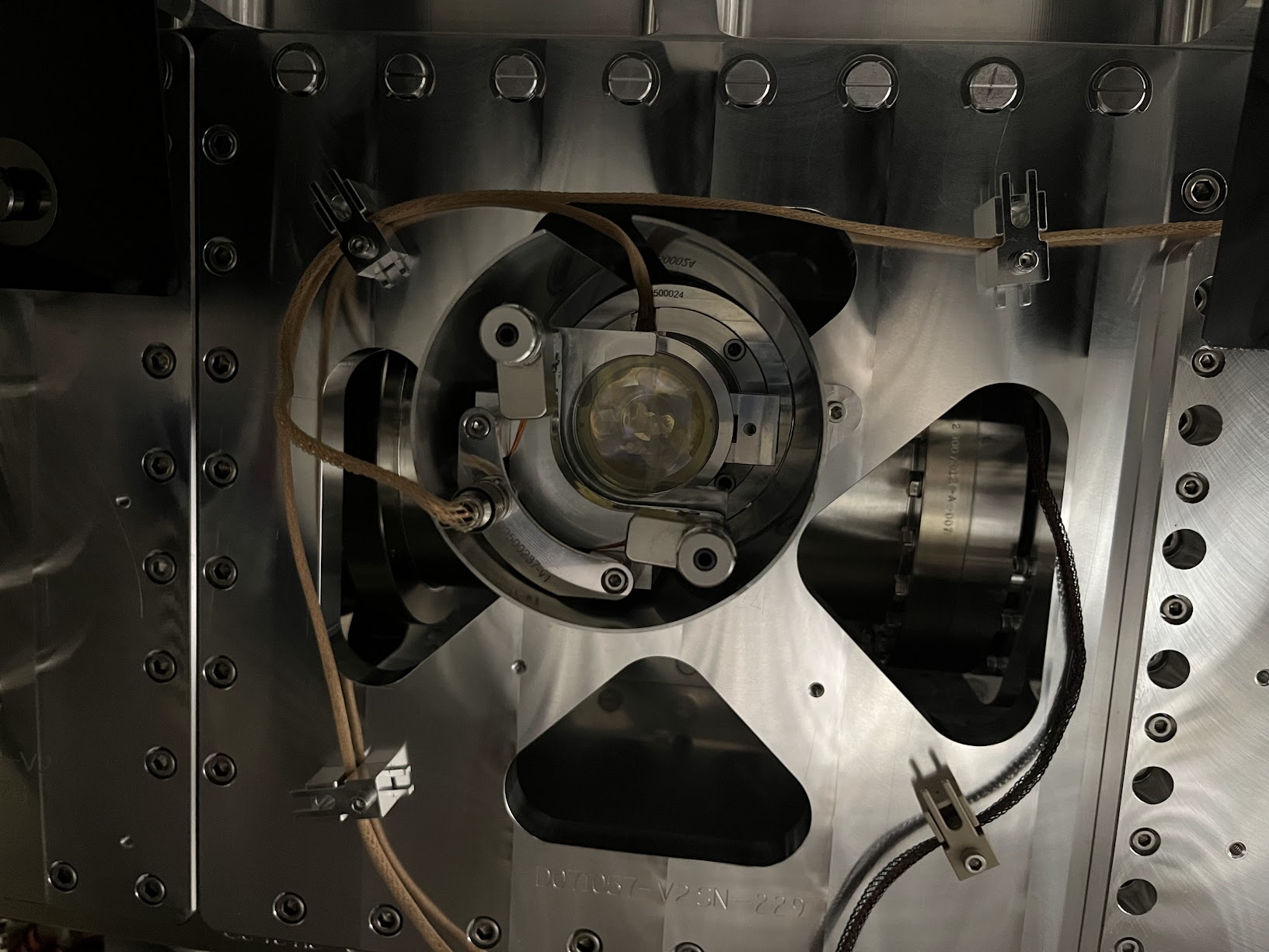
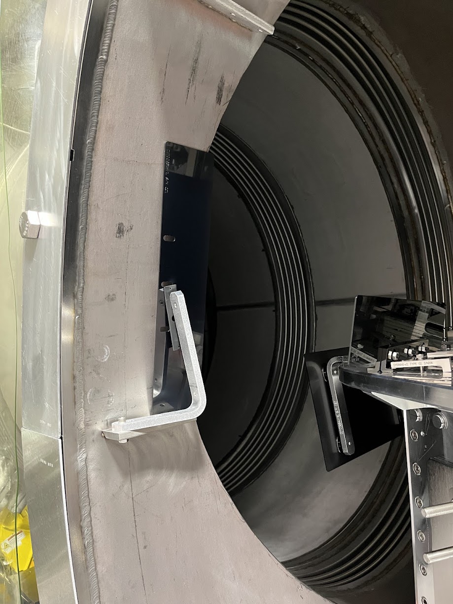
I went to HAM3 to see that the MC2 beam position wasn't crazy. See the first photo, the beam is to the left (+Y direction) relative to the baffle on the HR side but the baffle itself is offset in -Y direction relative to the cage. Green lines are extension of the EQ stop screws to guide your eyes.
I also opened the ISCT1 and moved the mirror in front of the REFL BBPD out of the way and directed the beam to IFO REFL camera (because I couldn't see the beam at all without moting the mirror).
While manually aligning the IMC, we found that somehow things are in such a bad state that the MC2 TRANS SUM decreases when IM4 TRANS SUM increases, and vice versa. Improving the IMC alignment using IM4 TRANS as well as IFO REFL camera made the flashes stronger to the point that we can see 00 mode once in a while. I was also able to see the beam in the ISS path. But MC2 TRANS was nowhere near centered. Attempts to resolve this by incremental changes failed.
We wondered if something behind MC2 was bumped and changed the alignment into MC2 trans. I looked at the path and didn't see anything obvious. The beam transmitted through MC2 was visible using a card and a viewer, it was not clipped by the baffle behind MC2 nor the BS for the beam dump. I could not see the transmission of the BS, though, it was too weak, so I cannot confirm if the steering mirror in front of the QPD was bumped or not.
Elenna started making big changes for JM3 in PIT (to make big YAW changes in the beam injected into IMC, remember that YAW and PIT are flipped between JAC and IMC, IMC WFS takes care of this but that won't help when you're manually aligning JM3) and moving MC2 and MC1 so that the IMC follows the input beam. Repeating this in YAW anShe successfully centered the beam on MC2 trans.
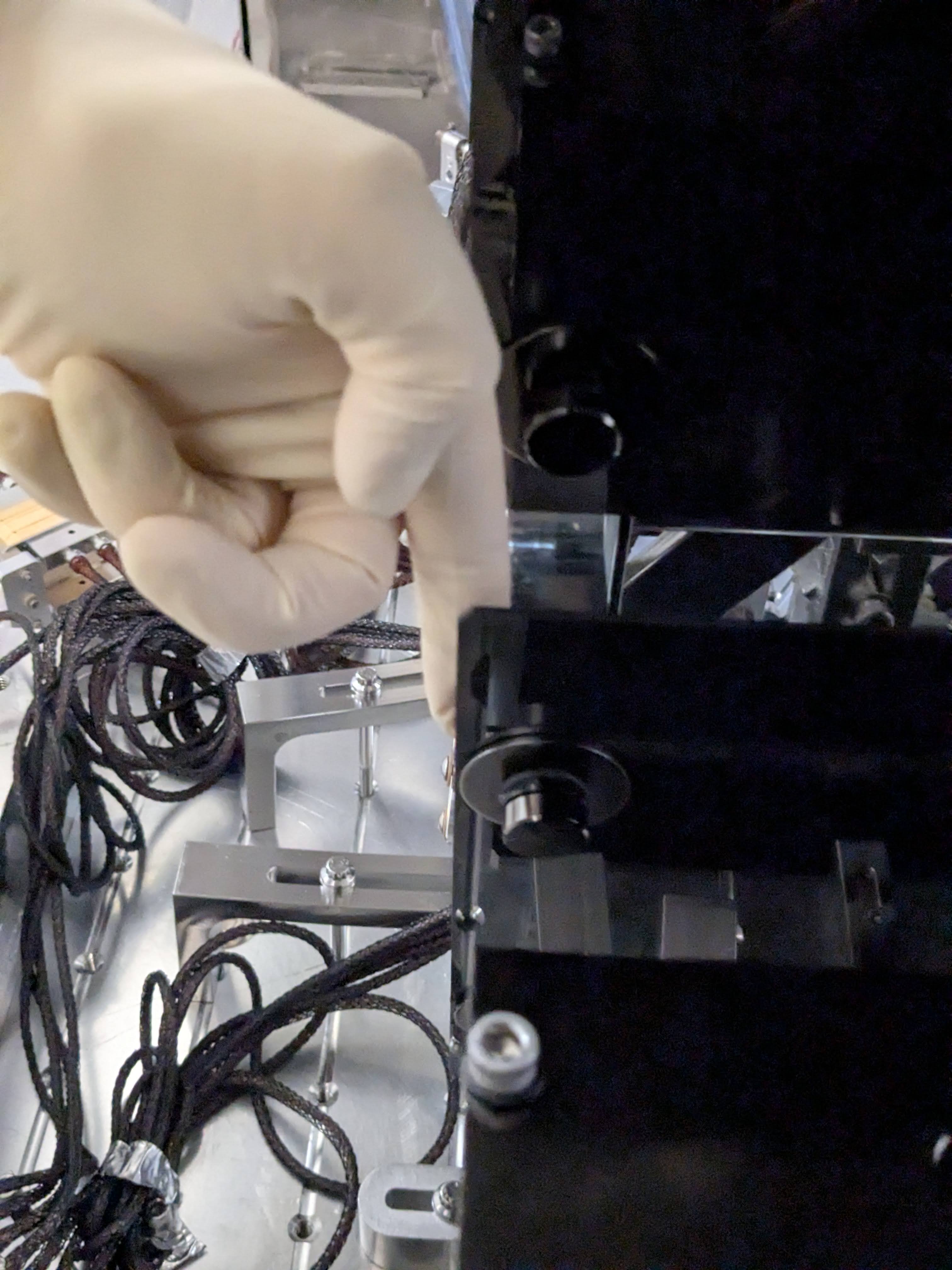
At this point I looked at the MC2 beam position again, see the second picture. Apparently the beam moved in YAW by a few mm to the right (i.e. -Y direction).
Elenna will post which optic was moved by how much in which direction.
Jenne is now trying to put IM4_TRANS and ISS QPD beam position back where they used to be using IM2 and 3.
We found that people opening BSC door cover(?) somehow disturbs IMC whether or not HAM3 and HAM2 door covers are on. The IMC fringe becomes super fast and it almost becomes impossible to align anything. Purge air seems to go to strange places to do strange things.
OTOH, when people are out of BSC, we had to put 0.2Hz 150cts excitation to MC2 M1 drive align L2L so the IMC goes across the entire FSR.
At first, I only moved some combination of MC1, 2 and 3 because we believed that the pointing into the IMC was fine. However, as Keita summarizes above, this was a futile process and veru confusing because it sometimes seemed as if the camera, MC2 trans QPD and IM4 trans QPD all gave differing directions.
However, although Keita said that the beam hit MC2 in a good place, he did clarify this was within mm, so this gave us room to move around JM3 by many microradians. Then, we had this whole realization that JM3 pitch and yaw are flipped relative to IMC pitch and yaw, so some of our other confusion about what we were walking (and why it wasn't really working) started to make sense.
In the end, this is the process that worked: move JM3 a large amount, follow up with MC2 move and some MC1 move in opposite dof (so JM3 pitch goes with MC2/1 yaw). At first, I relied only on IM4 trans, but then the flashes on MC2 trans started to improve, so this became a much more useful signal to follow.
Below, I compare the OSEM readbacks of each suspension from before we started moving to now at the end of the day:
JM3 pitch (IMC yaw): -177 urad
JM3 yaw (IMC pitch): -93 urad
MC1 pitch: -186 urad
MC1 yaw: +83 urad
MC2 pitch: +58 urad
MC2 yaw: -62 urad
MC3 pitch: + 12 urad
MC3 yaw: +21 urad
We should probably put some note next to the JM3 sliders that the pit/yaw dofs are flipped compared to IMC pit/yaw, or I predict that we will recommit this mistake many times over!
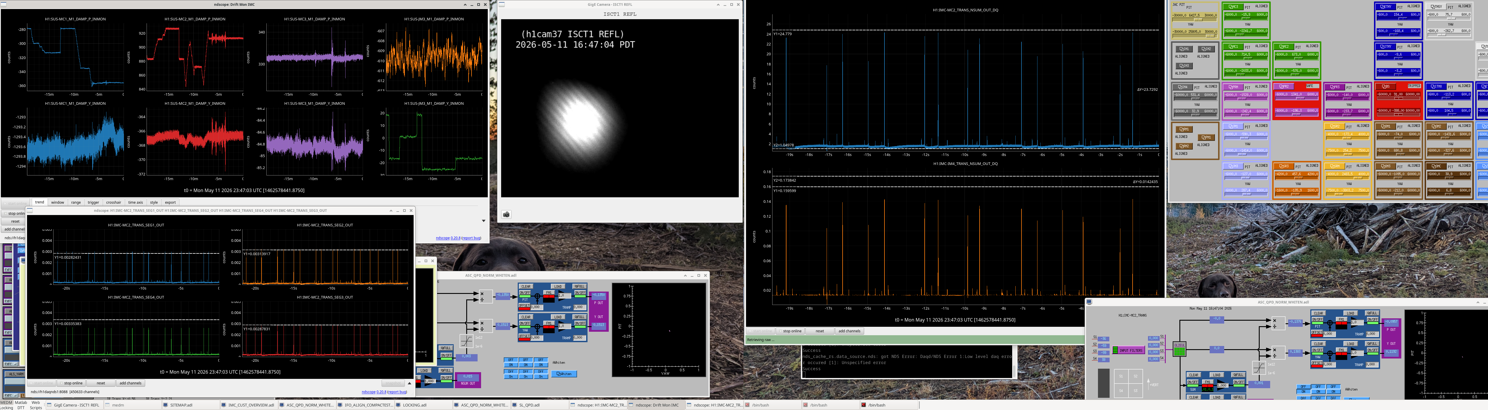
Attached is a screenshot of the IMC aligned in air with associated signals (and dog)
Once Elenna had the IMC nicely aligned, we moved on to setting the pointing of the beam headed to the IFO. We need this to be roughly correct, so that we can use it to align the ISS array.
Back in March when the IMC was locked, Elenna found the locations of the beam on IM4 Trans and ISS QPD:
We then worked to move IM2 to get to the right spot on IM4 trans, and then IM3 to get to the spot on the ISS QPD. The tricky thing is that, since we can't lock the IMC (IOT2 is away from the chamber, so no IMC REFL PD, so no IMC locking), we're just looking at flashes. So, the spot on the QPDs has to be calculated by looking at peak heights when we get a flash, and doing the matrix math to go from segments to pit and yaw.
.....After 23 different iterations of setting IM2 and IM3 based on an educated guess of where they should go, calculating the QPD spots, finding that we weren't quite right, and then tweaking again, we're leaving the IMs such that we're back to the March location on IM4 trans, but we're less on the edge for the ISS QPD. Current spots (calculated from the peaks of IMC flashes):
This helps assure us that we've got a pretty reasonable beam headed toward the ISS array, and that even if we didn't get the IMC alignment quite right earlier, we should be in a pretty reasonable place and we can use this beam to replace the ISS array.
One final thing we could do as a last check is to calculate the spots on POP A and POP B QPDs (or, at least the one that is used for initial alignment and acquisition), and make sure that we can move IM4 to get to that spot. That would mean that IM4 trans QPD and POP QPDs are both correct, which sets the pointing of the beam into the PRM and into the IFO, so if that line is correct in air and we use it to align the ISS array, then we will certainly be in a good place when we pump down. Again, this would just be a check that the IM1+IM2+IM3 position that we've got right now to give us good pointing to the ISS array is compatible with some IM4 pointing to the POP QPD. The individual segments aren't _DQed, so we'll have to check this tomorrow when the light pipe is open again.
Keita closed the light pipe for the night.
During the work noted above, I disabled IMC-IM4_TRANS whitening OFF (only one stage was on) because the fringe velocity was big-ish and made flash peaks of some quadrants distorted, which means either the whitening/dewhitening mismatch was a problem (likely) or the ADC was railing (unlikely).
Also, I held the output of H1:IMC-IM4_TRANS_SUM (to avoid dividing P and Y by a tiny number, but of course it was useless). NSUM wasn't changed.
Whitening is still OFF but I turned off the holding of H1:IMC-IM4_TRANS_SUM this morning.
I'll turn one stage of IM4_TRANS whitening back ON after we're done with ISS.
Ibrahim, Betsy, Rahul
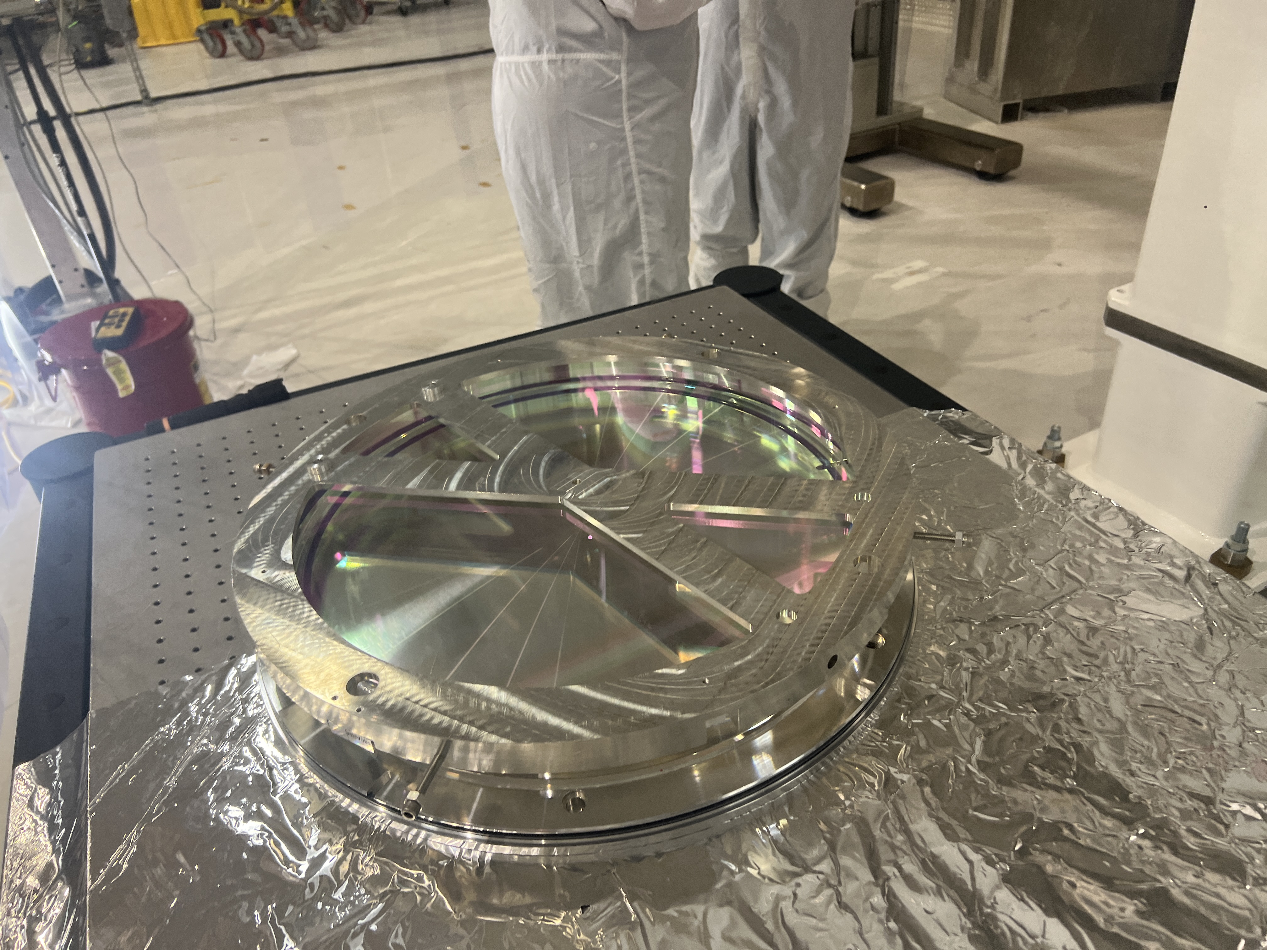
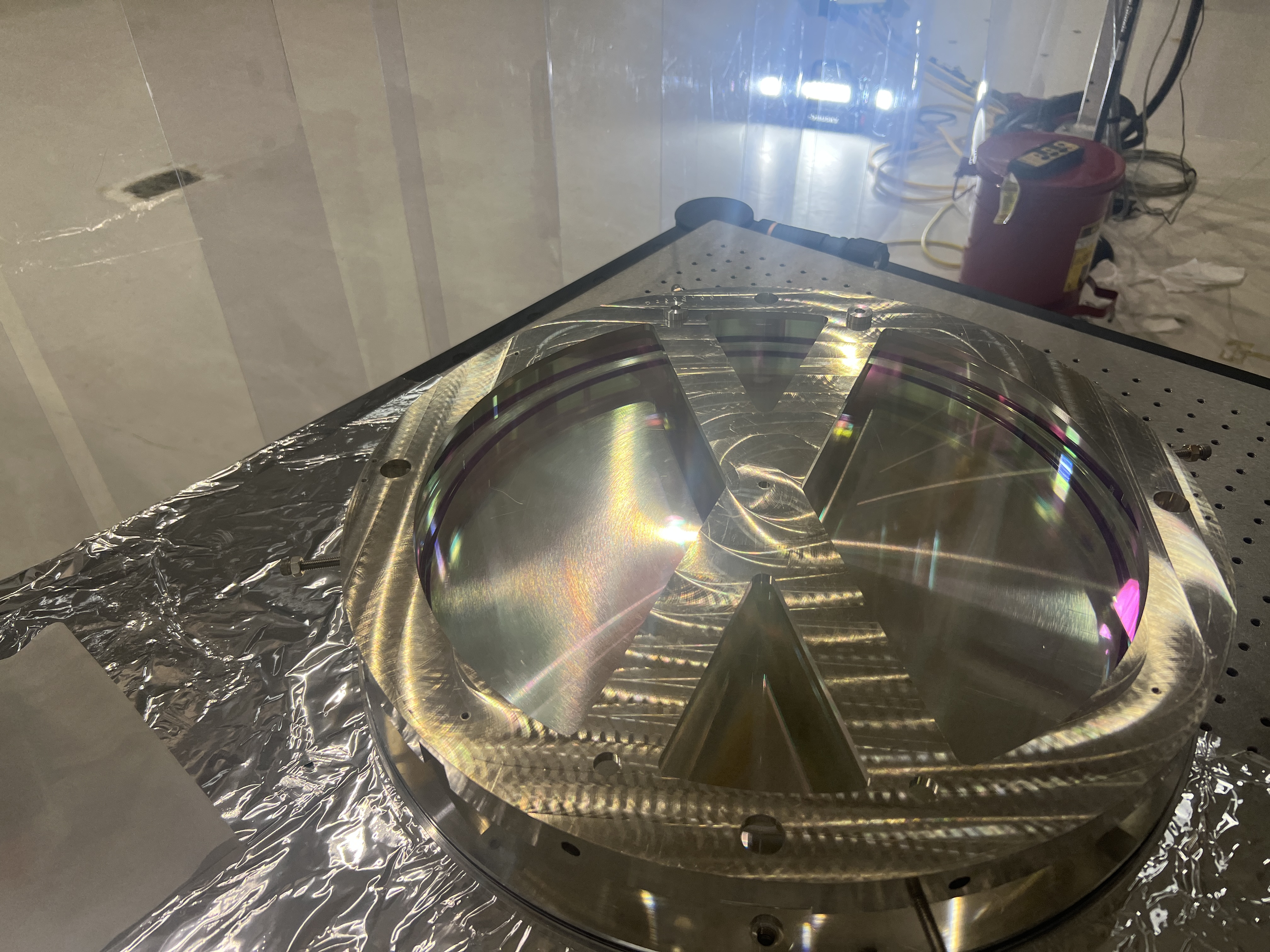
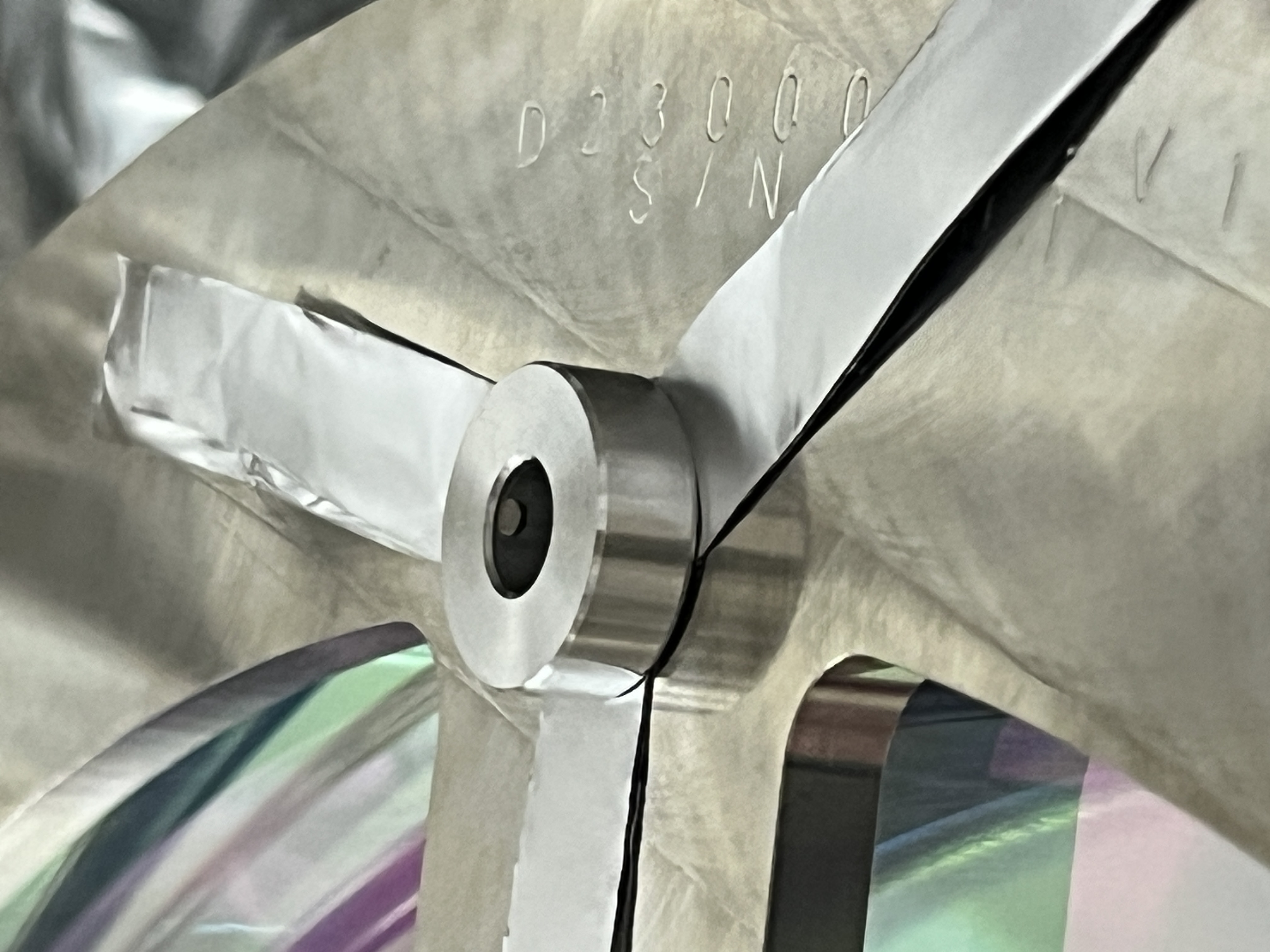
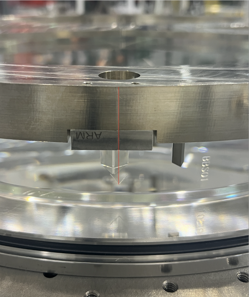
Today we glued two of the four AOSEM flag standoffs onto S2 of BBS01.
After gluing, we wanted to make sure we were contacted evenly so an hour and a half later, we used magnets to remove the flags from the glued-on mounts.
We discovered that some glue was touching the bottom of the magnet bushings, so we elected to use some foil as shims to create more space between S2 and the bottom interface of the bushings.
Otherwise, the mounts were flat on the surface. We put the bushings back on for the overnight cure. See pictures below.
TITLE: 05/11 Day Shift: 1430-2330 UTC (0730-1630 PST), all times posted in UTC
STATE of H1: Planned Engineering
SHIFT SUMMARY: The LVEA is still in laser hazard and will be for a few more days. The IMC alignment continues to prove difficult to get right. ITMY IAS finished up today. BBS work continues, CP1 regen, and more!
LOG:
| Start Time | System | Name | Location | Lazer_Haz | Task | Time End |
|---|---|---|---|---|---|---|
| 19:43 | SAF | LVEA IS LASER HAZARD | LVEA | Y | LVEA IS LASER HAZARD | 12:03 |
| 15:07 | VAC | Jordan | LVEA | yes | Checking on pumps and RGAs | 15:17 |
| 15:27 | CC | Ryan C | LVEA | yes | Grab dust monitor | 15:42 |
| 15:43 | FAC | Kim | LVEA | yes | Tech clean | 17:13 |
| 16:26 | ISC | Keita | LVEA | YES | HAM2/3 IMC alignment troubleshooting | 18:20 |
| 16:27 | ISC | Jenne | LVEA | YES | HAM2/3 IMC alignment troubleshooting | 17:03 |
| 16:27 | FAC | Randy | LVEA | yes | Measurements for more platforms around BSC3 area and emod area | 16:47 |
| 16:29 | IAS | Jason, Ryan C, Stephen A | LVEA | yes | ITMY Faroing in beir garten | 20:16 |
| 17:15 | VAC | Jordan | LVEA | yes | CP1 checks | 18:25 |
| 17:36 | FAC | Kim | LVEA | yes | Tech clean | 18:19 |
| 17:49 | VAC | Travis | LVEA | yes | CP1 work | 18:31 |
| 18:17 | SUS | Betsy, Ibrahim | LVEA | yes | BBS first contacting, suspension prep | 19:50 |
| 20:06 | SYS | Betsy | LVEA | yes | Checking that a chassis was turned back on | 20:12 |
| 20:07 | SAF | Ryan S | LVEA | yes | Checking on door | 20:17 |
| 20:38 | TCS | TJ, Madi | EX | Y | HWS table work | 23:20 |
| 20:40 | VAC | Jordan | LVEA | yes | HAM4 RGA | 22:48 |
| 20:42 | SUS | Betsy, Ibrahim, Rahul | LVEA | yes | BBS magnet gluing | 23:42 |
| 21:13 | ISC | Keita | LVEA | YES | HAM2 alignment | 21:50 |
| 21:21 | EE | Fil | LVEA | yes | HAM6 rack cabling | 00:21 |
| 21:36 | CAL | Tony | EX | - | Spinning up NCal | 21:36 |
| 21:48 | SPI | Jeff | Opt Lab | n | SPI work | 23:03 |
| 22:19 | SUS | Oli | CER | n | Taking rack pictures | 22:23 |
| 22:25 | PEM | Robert | EX | n | Grounding studies | 00:25 |
| 22:49 | VAC | Jordan, Gerardo, Travis | LVEA | yes | CP1 regen work | 00:49 |
| 23:09 | SEI | Jim, Michael, Shoshana, Stephen | LVEA | yes | Looking at cartridge and BSC2 | 01:09 |
FAMIS 63898 (I think. With the new system there are duplicate tickets, so I picked the one that has a schedule assigned.)
No major events of note this week.
Micheal Ross showed up in the control room, so we spun up the NCAL.
It wouldn't spin at first because there was a current Latch reset button that needed to be pushed. Michael pushed System Reset and Latch Reset in rapid succession.
More documentation can be found here: LIGO iNCal Operating Procedures.pdf T2600149-v1.
We ran it for 4 minutes 30 seconds starting at 21:25 UTC.
H1:CAL-NCALX_MOVE_VELOCITY_VELOCITY_REQ was set to: 104 which translates to ~ 0.991 hz.
H1:CAL-NCALX_VELOCITY_KP_REQ: 0.0100 Mn/rad/s
H1:CAL-NCALX_VELOCITY_FILTER_REQ: 5 ms
NCAL ran.
Beckhoff I/O H1:CAL-NCALX_AXIS_ERROR_ID now has an Error status.
Pressing the system reset button cleared this Beckhoff I/O error status indicator.
Jenne reminded us that with the installation of the JAC, the process we use to offload the IMC WFS should be updated to use JM3's alignment instead of the PSL PZT since it's now the alignment mirror directly upstream of the IMC. I've done this in the IMC_LOCK Guardian node's code by essentially just doing a "find and replace" for the term "PZT" with "JM3" (and double-checking the result, of course), all of which happened in the OFFLOAD_MCWFS state. We'll test this state's functionality at a later date.
Changes have been committed to svn and loaded.
TITLE: 05/11 Day Shift: 1430-2330 UTC (0730-1630 PST), all times posted in UTC
STATE of H1: Planned Engineering
OUTGOING OPERATOR: None
CURRENT ENVIRONMENT:
SEI_ENV state: MAINTENANCE
Wind: 10mph Gusts, 6mph 3min avg
Primary useism: 0.01 μm/s
Secondary useism: 0.12 μm/s
QUICK SUMMARY: IPC errors on h1susMC2 and h1seiproc, dackill on h1iopseib2. All sus aligned and damped, SEI in state captured by the whiteboard. Temps look good and dust counts look good in the LVEA, the ends saw counts up into the 2000s during the last bout of wind 12 hours ago.
Laser hazard work in the LVEA continues today.
[Tom R, Oli]
Summary: QOSEM testing on the BSFM will require the tablecloth to be shifted OR SUSP to be raised, probably not worth the effort to do so given the BBSS will be ready for QOSEMs shortly.
Last Friday Oli and I attempted to install the QOSEMs onto the now removed from chamber and on test stand BSFM suspension, now that the IAS work was completed. The purpose of this test is to run and compare TFs taken with QOSEMs, providing a final functionality test before installation on the BBSS (which is not yet ready to accept QOSEMs). The full test and integration plan for the QOSEMs / BBSS can be found here T2600169.
We began by removing the SD BOSEM from M1 of the BSFM, and swapping the flag out for the QOSEM variety. We installed the QOSEM onto the cage, and used the existing DB25 in vac extensions and in air cables to run the QOSEM to its sat amp in SUS-R2. The QOSEM and its entire signal chain was functional, with readouts from this SD QOSEM appearing as expected in CDS.
Unfortunately upon unlocking the suspension, to align this SD QOSEM, we found that its y axis could not be brought into range with the cams (at its best was ~1mm off). This is a similar issues we faced when setting up the BBSS at LLO. As the SD BOSEM does not have a readout in this 'y' or vertical direction, misplacement of the tablecloth by ~1mm is unnoticeable, and does not impede function of the BOSEMs, but as we are activity trying to readout this axis it does matter for the QOSEM.
As such, to setup the QOSEMs on the BSFM, we would need to raise the tablecloth, or SUSP via the blade spring angle. While this certainly could be done, at the moment this feels like an unnecessary amount of work to do for a quick test of the QOSEMs, given the BBSS will be ready shortly. For now we have abandoned this test, and removed the SD QOSEM from the BSFM, reinstalling the original BOSEM.
In order to search for retroreflections of scattered light that might recombine and cause scattered light noise, I take pictures from the point of view of the beam spot on important optics. The flash on the camera is right next to its aperture so, when the camera is held close to the location of the beam spot, the path of the light from the flash is similar to that of light scattered from the beam spot during observation, and glints in the photograph are indicative of potentiial retroreflections of scattered light. The distribution of light from the flash is, by design, more uniform than that of most scattered light, so more off-axis retroreflections in the photos tend to be less important.
An old photo taken from near the beam spot on PR3 showed a glint from an optic on the POP path so I re-took beam spot photos last week since we are baffling HAM3. The figure shows that I did not find a retroreflection in beam spot photos from PR3, but I did in photos from MC1 and from close to the center of PRM. I took beam spot photos with both my IR camera and cell phone – the figure shows cell phone photos as they are eaisier to interpret, but photos from both cameras show the same issues. I could verify these retroreflections and track them to their source by eye using a head lamp near my eyes. The PRM retroreflection is from the last optic on the POP path and the MC1 retroreflection is from the second to the last optic on the POP path (see diagram on the second page of the figure).
Im a little surprised that there are two of these random alignments, but I guess it is due to how small the angular differences between the paths from HAM3 to HAM2 are and the number of mirrors on the tables. I am also concerned that my beam spot photo technique only picks up retroreflections and not reflections of scattered light from one optic to a different optic. I would also like to make us more aware of these cross talk issues in planning optic paths and suggest that it might be worthwhile to develop code that checked for this.
I don’t know how bad these retroreflections are, but, in my photos, they are brighter than the reflections from ballast masses and the table that we are trying to baffle, so I may try to baffle the PRM retroreflection when we return to baffling. Im not sure how I could baffle the MC1 retroreflection without blocking the POP path.
Here is a layout that may be helpful for understanding some of Robert's photos above: HAM3 IO paths
Ryan Short, Tony Sanchez, Sheila
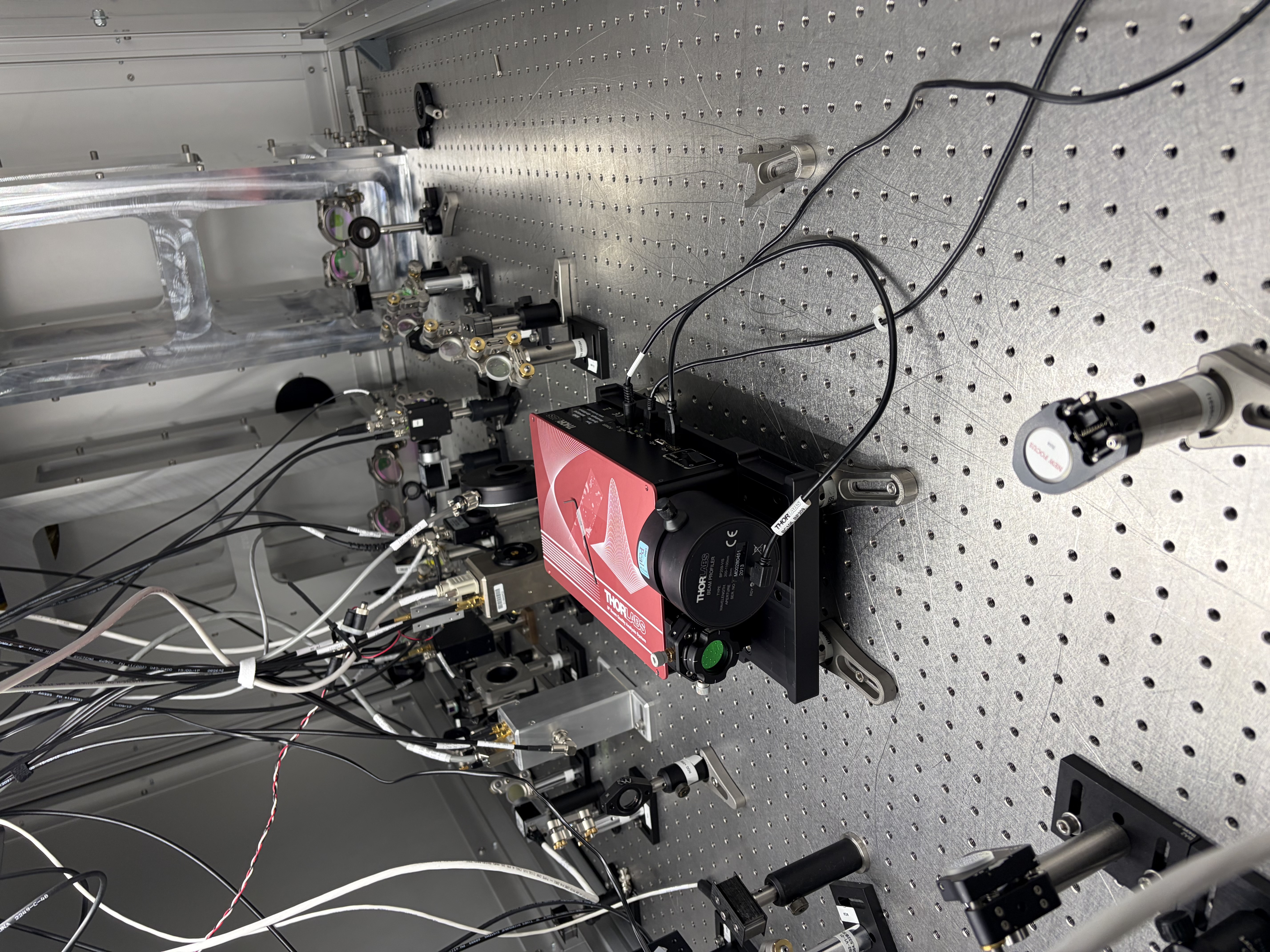
We took beam profiles of the sqz beam in the homodyne path using the Thorlabs M2Ms beamprofiler extension. It made collecting data for a variety of psams settings much faster than using a scanning slit profiler alone.
Tips for using this very nice extender kit:
We spent some time refinding the IR beam on the SQZT7 IR PD, documented this in it's own alog so it's easy to search: 90183
We set the profiler as shown in the attached photo. The flipper mirror is 50.75" from the bottom persicope mirror, a steering mirror is 225mm from that, and the reference plane is 260mm from the steering mirror, so the reference plane is 1.774 meters from the bottom periscope mirror. Leo Schrader has a helpful list of distances in the google document linked to T2500228.
Keita, Ryan Short, Tony, Sheila
In the saved PDFs, the units on "Beam Waist Position" are listed as um, but in the text file (which does contain all the same information), the values are the same but the units are mm. mm must be the correct units.
Looking at T2500077 we believe that to get from the reported Beam Waist position in the text file we need to add (z_stage_min - 4.4 mm= 122.9mm) to the distance from the reference plane as depicted in that diagram to the waist position. We believe that this waist position being positive means that the waist is after the reference plane (on the sensor side of the reference plane), I think a negative number would mean the waist is before the profiler.
I asked Claude to write a script to collect the data from the txt files in the archive above and save it in a yml, the script is attached here in case someone else wants it.
I had further correspondence with Thorlabs tech support about understanding what the "beam waist position" is relative to. I believe that for the "original waist position" a positive number means the waist is closer to the source, and is reported in mm from the reference plane. the after lens measurement seems to have the opposite sign, and I am not sure how the value given relates to the reference plane.
J. Kissel, J. Warner ECR: E2400026 WPs: 13237, LHO:13238 Final Design Doc: T2400145 Relevant Systems Level Drawings: . Mechanical Assemblies :: ISIJ Reflector D2400102 :: HAM Table Baffles D1700335 :: HAM2 Systems Layout D0901083 (not yet-inclusive-of-SPI) . Electronics Wiring Diagram . Cable Routing In-vac Cable Routing Plan from G2401479 (pages ) . Flange Layout D1002873-v11 Executive summary: - Removed ISIJ +X-side, center, HAM2 ISI table baffle from D1700265-v4 Type 2 :: Bracket mounting bolts left screwed into ISI optical table for this will eventually become a D1700265-v4 Type 3 and remounted. - Installed ISIJ Reflector + QPD Assembly D2400102 on +X ISI side wall (D071057-v2), with its shroud (D2500030) in place :: We didn't weigh it, but the SW Assembly predicts a mass of 1.96 [kg], which we can likely round up to 2.0 [kg] with the shroud installed. - Routed and connected QPD read-out cable system to D3 flange, F10 spigot. - Routed and connected picomotor cable system to existing D1101515 quadrupus leg Cable #3, J4 :: Cable #4, J5 is connected to IO PM5 mirror, Cables #2 J3 and #1 J2 were reset in neat coil with connectors floating to avoid electrical grounding as before. - Nudged make-shift baffle system using D1700261 ballast mass baffle mounted vertically on the +X / +Y / Beam Height corner of the chamber wall upon entry into beamtube. :: the will DEFINITELY need a technically-minded reset. In at 10:30a PT and out by 12:30a PT. It's so lovely when everything goes to plan! Pictures and further info to follow in the comments below.
Removing Center ISI Table Baffle Not much to say more here -- removal was easy. We tried "just" removing the panel using the the coated/capped screws, but these didn't budget upon several attempts with Jim's fingers and grunts. So, elected to fight that battle outside the chamber and removed the whole assembly at the table mounting point. The full assembly is wrapped in dry-wipes, foil, and ameristat bagged and in Mitch's office while it waits for the Type 03 version of the panel to come out of clean-n-bake.
Installation of ISIJ Reflector itself Also not much to say, other than the great joy that the drawings of the D071057-v2 ISI Side Wall have the irregular positions of the 1/4-20 utility holes accurate enough that Bram's CAD-informed-only mounting holes for the ISIJ reflector's baseplate of the reflector lined up without issue. *phew* Also -- the D2400102 drawing doesn't highlight which length 1/4-20 bolt should be used for mounting, so we used 1/4"-20 x 0.625"L (5/8"), which was "just enough." Pictures from the main entry are the best "big picture" views, but here I attach a few more in case the need arises.
QPD Cable Routing
We didn't get dedicated pictures of this QPD cable routing but,
- it follows the plan on page 22 of In-vac Cable Routing Plan posted to G2401479-v3,
- You can see the ST1 portion of it well-enough in the above pictures,
- Jim did the routing, so I trust that there's a healthy loop in the jump from ST1 to ST0, and
- I attach a picture here of the record that we've connected it to D3-F10, and a copy of the "F-Type" (D2000225-v1) counting from page 18 of the above mentioned cable routing plan.
Picomotor Cable Routing BEFORE INSTALL Just because we knew little about the details of this cable system ahead of time given how ancient the PM5 picomotor actuated mirror system, I got a lot of good "before" pictures. Mostly, I confirm that PM5 does use the Cable #4 J5 leg of the D1101515 quadrupus, and all the other legs were neatly cable-tied up and away.
Picomotor Cable Routing AFTER INSTALL Here're photos of the routing of the two 72 [in] length D2400316 picomotor extension cables connected in series and routed to all the way around from the ISIJ reflector on the +X face to the -X / +Y corner of the table where CB-9 and the D1101515 quadrupus lives. I paid particular attention to the connectors and made sure they were left floating and not shorting to anything metal. I also re-bundled up Cable #2 J3 and Cable #1 J2 in coil similar to the before pictures, again ensuring that the connectors are floating in both space and electrical connection.
The Nudged Chamber Wall Baffle Some pictures of the baffle that we nudged that will likely need re-alignment.
tagging for photos.
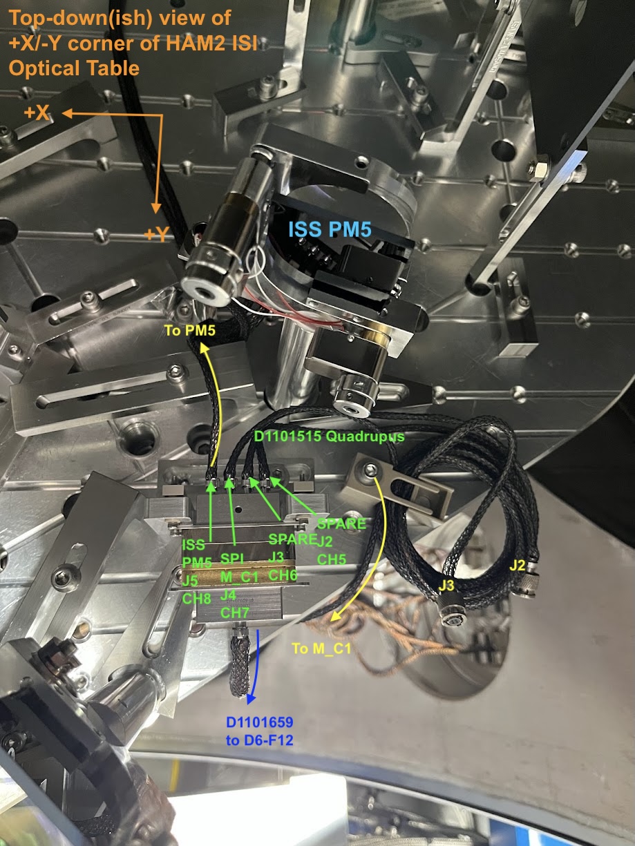
On the new channel assignment of HAM2's SPI ISIJ picomotor, and why I'm confident it's CH7: Per D1000581-v13, page 13 and then D1900511-v12 page 17, I'm quite confident that the quadrupus cable and up in CH5-8 of the controller on IOT2L, called "PICOMOTOR 5" in D1900511, which I guess becomes "Picomotor B / Slot 2" on page 2 of the ECAT System Diagram D1100683-v11. This is corroborated with opening up the picomotor MEDM screen -- sitemap > LSC > picomotors > "HAM 2 + oplev" button (that has "controller 5" and "PICO B" next to it), and clicking through the channels and seeing that CH8 is called "PSL ISS QPD/PD (PM5)." Here's a labeled picture that makes things more clear.
Belated aLOG on in-vac cable routing of the ISIJ QPD A PD and serial number assignments:
Path PD Name PD SN Monopus D9-to-D25 Monopus
|----------D2600002--------|
D1600083 Type 3 D2400340 D2300128
OL ISIJ QPD A S2401092 S2500517 S2500511
Camille (CIT), Austin , Rahul
This morning we went to HAM7 chamber and changed the preload on ZM4 (P-SAMS) suspension as per the document E2300463_V1. This changed the RoC of ZM4 mirror without the PZT actuation. Given below are the details of our work - Camille will add pictures later on.
- After setting ZM4 into SAFE state we locked all three stages of the suspension. We had already taken healthy TF measurements before starting our work.
- The bottom mass cable was disconnected and carefully re-routed so that it stays away from the fixture plate.
- four add-on masses (basically 1/4-20 screws with washers) attached to the bottom mass was then removed.
- bottom mass Fixture plate (D2100121) was attached to the structure using six 8-32 screws.
- The bottom mass (already locked using EQ stops) was then further clamped using four 1/4-20 screws through the fixture plate. We had to adjust the height of the bottom mass to the align the threads with the holes on the fixture plate.
- Once the bottom mass was securely clamped, we removed the three set screws on the preloader.
- Using a torque wrench we increased the preload on the bottom mass by ~29 in.lb. (Total preload from torque after increase was 75 in.lb).
- We then followed all the above steps backwards (i.e set screws, add on mass put back, fixture plate removed, cable re-connected and the suspension set free).
- Once all done, we started damping the suspension and checked for any BOSEM flag changes - looked all fine.
- We took the transfer function measurements and ZM4 looked healthy.
Hence we took all the tools out and put the curtains back on HAM7 chamber.
Next, we will go into laser hazard with SQZ team and check for any changes in beam alignment and make adjustments as required.
1st image: PSAMS locked in place with EQ stops. 2nd image: PSAMS locked with bottom mass fixture plate. 3rd image: Removal of set screws. 4th image: Preload adjustment with torque wrench. 5th image: Preload adjustment with torque wrench. 6th image: Torque wrench dial with the blue needle showing the total torque on the preloader (75 in lbs.)
Excellent!
ZM5 offloaded as well, see LHO alog 75709.
This is ZM4 SN1, so it's original charachterization data (before this preloading) is in E2100289, where with 0 V applied to the PZT the optical power is -106mD (or ROC is -18.877m).
According to T2300426, changing the preloading changes the optical power by 2.4mD/in.lb. So, after this preloading the optical power with 0V on the PZT should have been -36mD, or the ROC should be -55.5meters.
Evan and Camille noticed that I flipped a sign here:
The preloading should make the magnitude of the optical power larger, so it should be increased to -106mD - 2.4mD/in lb * 29 in lbs = -175.6 mD with 0 V on the PZT. ROC = 1/-175.6e-3 = -11.4 meters
In 90859 we've used measurements to find the new ROC.