Displaying reports 75981-76000 of 83466.Go to page Start 3796 3797 3798 3799 3800 3801 3802 3803 3804 End
Reports until 14:34, Wednesday 11 September 2013
H1 IOO
cheryl.vorvick@LIGO.ORG - posted 14:34, Wednesday 11 September 2013 (7729)
IMC LSC gain issue found (sort of), locking restored, WFS not working, death trap for IFO found (unfortunately)


- Patrick, Cheryl, Jeff, Kiwamu 

Morning spent with Patrick and I investigating IMC poor locking, i.e. only brief locks.  Keita started us on the issues of too much gain on H1:SUS-MC2_M2_LOCK_L_GAIN, which he changed form 0.2 to 0.008, in order to get any locking last night. 

Looked at Stefan's autolock script and the channels it changes, and all was OK. Compared MC Common Mode channels/settings, all was OK. 

Tracing the GAIN path backward, I found we could lock with autolocker settings and MC2_M2_LOCK_L_GAIN at 0.2, if I lowered the overall MC2 LSC gain from 1.0 to 0.15. 

Jeff joined us, we burt restored h1lscepics and MAGICALLY the IMC locked with the MC2 LSC gain back at 1.0!  Somehow that fixed the gain issue, though we have not located the exact setting that changed.

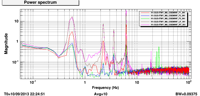
At this point Jeff reenabled HAM2 ISI and set it to Level 3 isolation. This helped with 1Hz oscillation seen in REFL. Then we set HAM3 isolation to Level 3 from Level 2, and further decreased the 1Hz noise. This allowed for a long lock and I was able to align manually to get REFL down to 240 and MC TRANS around 2200.

We tried to engage WFS, but found it driving the lock to a bad place, REFL = 800. Kiwamu arrived, and is now working on WFS.

WFS are not well aligned, and MC2 TRANS QPD is high in pitch.  This means the IMC alignment is good for REFL, but not for the IMC as a whole, which could be my alignment changes to MC1, or changes in the PSL input beam pointing from PZT's being turned off and on yesterday (see NOTE), or changes to the PSL input beam pointing from temperature change made by Rick in the PSL enclosure, or all 3 combined.

NOTE... I ran scripts attached to the WFS medm screen yesterday, which apparently have NEVER been run here before, and were written at LLO.   Why do we do this to ourselves?  I was telling Jeff the script to turn off ASC turns off the PZT offsets WHICH SHOULD NEVER BE TURNED OFF!!!  Now I learn from Kiwamu that no one has ever run any of those scripts at LHO.  Are these scripts even used at LLO?  This sort of thing is a death trap for an IFO.

Currently Kiwamu is working of WFS.

X1 SUS
stuart.aston@LIGO.ORG - posted 13:49, Wednesday 11 September 2013 (7728)
X1 tripleteststand configured ready to accept Phase 1b testing of OMC suspensions
The staging building X1 triple test-stand has been configured ready to accept OMC (OMCS) suspensions for Phase 1b testing. This procedure is similar to that which I had previously carried out on the LLO triple test-stand (see LLO aLog entry 6842).

I've remotely logged-on and set-up the test-stand as follows:-

1) svn'd up the /ligo3/svncommon/SusSVN/sus/trunk/OMCS$ directory

2) svn'd up the /ligo3/svncommon/SusSVN/sus/trunk/Common$ directory

3) Started the x1sushxts05 model, thanks to the local efforts of Jim Batch (see LHO aLOG entry 7727).

4) Burt restored the most recent working triple suspension configuration from /opt/rtcds3/tst/x1/userapps/release/sus/x1/burtfiles/20120911_x1sushxts05_PRM.snap

5) Reset all stage OSEM INPUT FILTER gains and offsets to their default values, +1 , and -15000 counts, respectively.

6) Used updated ligo3/svncommon/SusSVN/sus/trunk/OMCS/Common/MatlabTools/make_susomcs_projections.m Matlab script to populate OSEM2EUL and EUL2OSEM matrices with elements for OMCS geometry, using the "fill_matrix_values" script, as follows:-
- fill_matrix_values('X1:SUS-HXTS_M1_OSEM2EUL',OSEM2EUL.M1)
- fill_matrix_values('X1:SUS-HXTS_M1_EUL2OSEM',EUL2OSEM.M1)

7) Copied M1 DAMP filter block and gains from LLO triple test-stand.

8) Taken a new safe BURT snapshot, which has been committed to the svn, /opt/rtcds3/tst/x1/userapps/release/sus/x1/burtfiles/20130911_x1sushxts05_OMC.snap

Finally, to expedite testing, I've copied over some of the most relevant DTT OMCS templates from X2, in which the excitation amplitudes have already been tuned to optimize coherence in all 6 DOFs. These DTT templates (and accompanying exported ASCII data) are available on the svn as follows:-

X1/OMC/SAGM1/Data/2013-09-11_1200_X1SUSOMC_WhiteNoise_L_0p1to50Hz.xml
X1/OMC/SAGM1/Data/2013-09-11_1200_X1SUSOMC_WhiteNoise_T_0p1to50Hz.xml
X1/OMC/SAGM1/Data/2013-09-11_1200_X1SUSOMC_WhiteNoise_V_0p1to50Hz.xml
X1/OMC/SAGM1/Data/2013-09-11_1200_X1SUSOMC_WhiteNoise_R_0p1to50Hz.xml
X1/OMC/SAGM1/Data/2013-09-11_1200_X1SUSOMC_WhiteNoise_P_0p1to50Hz.xml
X1/OMC/SAGM1/Data/2013-09-11_1200_X1SUSOMC_WhiteNoise_Y_0p1to50Hz.xml

This should now provide sufficient infrastructure to proceed with Phase 1b testing of the OMC suspensions.
X1 SUS
james.batch@LIGO.ORG - posted 12:06, Wednesday 11 September 2013 (7727)
Start x1sushxts05 model on tripleteststand computer
I have the x1sushxts05 model running now. 

In X1SITEMAP_TRIPLES.adl, the macro substitution used for the 05 models used FEC=17 instead of FEC=18.  I changed the macro to use FEC=18 for both HLTS05 and HSTS05, which allowed me to open a working X1SUSHXTS05_GDS_TP medm screen.  This in turn allowed me to press the BURT button after the X1 IOC started, which allowed the model to continue to run.

It's been broken for quite some time, so I don't know why the wrong FEC number was in the X1SITEMAP_TRIPLES.adl file.

I note that there appears to be an excitation test point 119 that shows up on the GDS_TP screen.  When I run diag, it indicates no test points are set, and no excitations are running.  Not sure where it's coming from, but if it bothers you I can try harder to get rid of it.  It'll probably involve rebooting stuff.
H1 DAQ
david.barker@LIGO.ORG - posted 10:20, Wednesday 11 September 2013 (7725)
DAQ Restart, added GPS slow controls channels

I restarted the daq. It was configured to read the Beckhoff GPS EPICS channels from the timing master with a new ini file (H1EDCU_GPS.ini)

H1 IOO
keita.kawabe@LIGO.ORG - posted 20:10, Tuesday 10 September 2013 - last comment - 11:46, Wednesday 11 September 2013(7724)
IMC locking

Cheryl reported that IMC wouldn't lock and WFS was breaking the lock.

When I came into the control room the DC alignment of MC seemed OK. Disabled ASC output and manually enabled the PZT offset.

MC2 M3 watchdogs were found tripped, and assuming that this stage is necessary for locking I reset the watchdog.

After this IMC would lock but it lasted for 3 seconds that's incidentally the same as the ramp time for M2 and M3 lock filter. The lock was repeatedly broken by an oscillation at a few Hz that develops right after M2 and M3 lock filters were turned on.

I disabled the L-L element of the drive align matrix of M2 and M1, and the lock would last until the M3 coils rail.

Apparently something changed between this morning and afternoon, and now I had to make the M2 and M1 gain ridiculously small, otherwise a few Hz oscillation just kills the lock.

For the moment I changed the setting in Stefan's lock script such that H1:SUS-MC2_M2_LOCK_L_GAIN is 0.008 (VS the nominal 0.2) and M1_LOCK_L_GAIN is 0.3 (VS the nominal 1). I didn't fix anything, whatever the problem is it's still there, and the lock lasts for only a few minutes at most until M3 coils rail.

I haven't done anything to WFS, I don't know if it was doing something bad, but the DC alignment right now is OK.

Comments related to this report
jameson.rollins@LIGO.ORG - 11:46, Wednesday 11 September 2013 (7726)

Yesterday I was testing some Guardian IMC locking code around the time that Cheryl was trying to fix the alignment.  While I don't see how this could have broken anything, it's well within the realm of possibility that it did, so I will look into it.

The guardian code that I was testing is designed to be identical in function to Stefan's locking script.  I grep'd through the locking code for all channel access writes and this is what I found (all paths are relative to the userapps root /opt/rtcds/userapps/release):

H1:IMC-:

ioo/common/guardian/states/DOWN/run:ezca.write('REFL_SERVO_IN1GAIN', -10)
ioo/common/guardian/states/DOWN/run:ezca.write('REFL_SERVO_COMBOOST', 0)
ioo/common/guardian/states/BOOST/run:ezca.write('REFL_SERVO_IN1GAIN', 0)
ioo/common/guardian/states/BOOST/run:ezca.write('REFL_SERVO_COMBOOST', 1)

H1:SUS-MC2_:

sus/common/guardian/MC2/states/PRELOCK/run:ezca.write('M2_LOCK_L_GAIN', 0)
sus/common/guardian/MC2/states/PRELOCK/run:ezca.switch('M2_LOCK_L', 'FM3', 'OFF')
sus/common/guardian/MC2/states/PRELOCK/run:ezca.write('M1_LOCK_L_GAIN', 0)
sus/common/guardian/MC2/states/PRELOCK/run:ezca.switch('M1_LOCK_L', 'FM1', 'OFF')
sus/common/guardian/MC2/states/IMCLOCK/run:ezca.write('M2_LOCK_L_GAIN', 0.2)
sus/common/guardian/MC2/states/IMCLOCK/run:ezca.switch('M2_LOCK_L', 'FM3', 'ON')
sus/common/guardian/MC2/states/IMCLOCK/run:ezca.write('M1_LOCK_L_GAIN', 1)
sus/common/guardian/MC2/states/IMCLOCK/run:ezca.switch('M1_LOCK_L', 'FM1', 'ON')

In addition, to the above SUS-MC2 writes, there are additional SUS-MC2 writes performed by the SUS base guardian code (sus/common/guardian/common) via the sustools library (sus/common/guardian/sustools.py).  It is my understanding the that sustools.py library has been previously, although maybe not on SUS-MC2.  We should consult with the SUS team to confirm that their SUS library is indeed switching things as intended.

Those channels are really all the stuff that guardian would have touched (which I guess is potentially a lot).

I am investigating the remote possiblity that the ezca.switch() python function (part of the guardian ezca library guardian/python/lib/guardian/ezca.py) is writing something strange to the switch settings.  I don't think this is happening, since it has been tested, but I'm looking into it just in case.  I'll report back here either way.

H1 SUS
arnaud.pele@LIGO.ORG - posted 18:26, Tuesday 10 September 2013 (7721)
TMSX BIO bit

One of the BIO bit representing the status of the analog dewhitening filter of the TMSX is either not displaying the right value, or the dewhitening filter is not switched to the requested state, cf bit 8 (RT LP) of picture attached. I will check tomorrow with Richard to see where the problem could come from.

Images attached to this report
H1 SUS
jeffrey.kissel@LIGO.ORG - posted 18:17, Tuesday 10 September 2013 (7720)
V/R 6.18 [Hz] Feature is NOT a function of the Drive
J. Kissel

Here're some spectra that are the same as what Vincent had posted, but focused on the LF and RT OSEMs, and calibrated into [um/rtHz]. I show four configurations (each config has the ISI/HPI in its best performance state):
(1) As we discovered the problem, with all SUS damping loops closed (shows giant feature)
(2) With only V loop turned off (still shows giant feature)
(3) With V and R loops turned off (does NOT show giant feature)
(4) With V and R loops turned off, and with a broad-band 1000 [ct] excitation sent out of the RT COILOUTF bank (does NOT show giant feature).

Note, I also measured 
(5) With only R loop turned off (still showed giant feature), 
(6) With V and R loops turned off, and with a broad-band 1000 [ct] excitation sent out of LF COILOUTF bank (still did NOT show giant feature), 
(6) With V and R loops turned off, and with a broad-band 100 [ct] excitation sent out of LF COILOUTF bank (still did NOT show giant feature), 
(6) With V and R loops turned off, and with a broad-band 10 [ct] excitation sent out of LF COILOUTF bank (still did NOT show giant feature), 
but they were redundant with the above information, and would have over-crowded an already crowded plot.

First page of the attachment shows configurations (1)-(4). Second page shows the ASD of the 1000 [ct] excitation, meant to look roughly like a damping loop signal. 

Given that we only see this feature with the damping loops that involve LF and RT ON, and we don't see it by turning the damping loops OFF and driving an artificial, non-OSEM-sensor, signal AND we know it's not a loop instability, I think we can narrow down the source to something in the analog sensing chain that is oscillating.

We should replace the M0LFRT, R0LFRT satamp tomorrow, and see if this feature goes away. I blame the satamp, because the satamps have plagued use wih a terrible history of oscilliations.

I bet $1.00 USD.

If anyone is betting against, please please please, shoot me more ideas on how to narrow down the source further.
Non-image files attached to this report
H1 SUS
jeffrey.kissel@LIGO.ORG - posted 17:59, Tuesday 10 September 2013 (7719)
V/R 6.18 [Hz] Feature is NOT a Loop Instability
J. Kissel, V. Lhuillier

With all SUS damping loops closed and with the ISI in full isolation, I've taken open loop gain transfer functions of the H1 SUS ITMY's Vertical and Roll Level 2.1 damping loops. As predicted by design, and by what was seen on H1 SUS ETMY there is plenty of phase margin, and no features around 6.18 [Hz].

NEXT: Determine whether it's the coils or the sensors, or some nasty interaction between them.
Non-image files attached to this report
X1 SEI
sebastien.biscans@LIGO.ORG - posted 17:28, Tuesday 10 September 2013 - last comment - 17:56, Wednesday 11 September 2013(7718)
Test Stand BSC-ISI Unit6 issue

Sebastien, Jim

We are currently testing the BSC-ISI unit #6 in the staging building. The 2 stages are unlock and balanced, everything seems to be well connected.

The power spectra show something wrong on GS13-V1 and GS13-V3 (see figure attached).

After further investigation, the issue seems to be 2 bad cables. They will be change tomorrow.

Images attached to this report
Comments related to this report
sebastien.biscans@LIGO.ORG - 15:07, Wednesday 11 September 2013 (7731)

***UPDATE***

We tried a bunch of different tests today.

1. We swapped GS13-V2 (good signal) with GS13-V3 (bad signal). Now the GS13-V3 presents a good behavior: the issue doesn't seem to come from the sensor.

2. We swapped, one by one, all the cables between corner 2 and corner 3 (in-air cables, extensions, sensor cables). Those changes didn't affect the results observed: the issue doesn't seem to come from the cables.

3. We plugged the corner 3 GS13s into another feedthrough (L4C feedthrough). No changes: the issue doesn't seem to come from the feedthrough.

4. We swapped the electronics of GS13-V2 and GS13-V3. The issue follows the swap: it doesn't seem to come from the electronics.


Thus no conclusion so far. Please let us know if you have any input. We'll think about it and continue the tests tomorrow.


sebastien.biscans@LIGO.ORG - 17:56, Wednesday 11 September 2013 (7735)

Find attached a more graphical way to look at all the tests we have done so far.

Non-image files attached to this comment
H1 ISC
alexan.staley@LIGO.ORG - posted 17:28, Tuesday 10 September 2013 - last comment - 21:13, Thursday 12 September 2013(7715)
ISCTEY information cont

In the optimal laser configuration (current = 1.503A, see alog7695), the power before ALS-FI2 was measured to be 39.7mW, while the power after the FI was measured to be 37.6mW. Thus, the throughput of the ALS-F12 was about 94.7%. The first jpg (532nmALSfI2FullCurrent.jpg) shows the beam profile after the ALS-FI2.

The first pdf (BeamProfile532nmRefALSFI2.pdf) is a graph displaying the mode measurement of the 532nm beam with ALS-F12 as a reference. Meanwhile, the second pdf (BeamProfile1064nmRefALSM1.pdf) is a graph displaying the mode measurement of the 1064nm beam with ALS-M1 as a reference. Using the 13.5% width (or 1/e^2 diameter) of both the horizontal and vertical profiles, the radii for the two profiles were determined at various distances from the respective reference points. In addition, the graph includes error bars of one standard deviation. A line of best fit was produced, and the difference between the line of best fit and the data points was plotted in the lower portion of both figures.

Images attached to this report
Non-image files attached to this report
Comments related to this report
alexan.staley@LIGO.ORG - 21:13, Thursday 12 September 2013 (7757)

Sorry, I meant ALS-FI3 in the table layout.


Also, as of today, we have moved the laser 1inch closer to the beam path (relative to when the beam profiles mentioned in the alog were taken).

LHO General
cheryl.vorvick@LIGO.ORG - posted 17:19, Tuesday 10 September 2013 (7716)
OPS"


Kyle - replace transducer at EX

TMSX measurements lst night

TMSX - Keita and Corey in AM - Betsy, Jeff, Andres in PM - gone now - TF running

BS - alignment in LVEA test stand - some alarms

IMC - Jamie working on Guardian, IMC has drifted out of alignment, WFS won't engage, left off waiting fix

H1 SUS
arnaud.pele@LIGO.ORG - posted 16:14, Tuesday 10 September 2013 (7705)
BS phase 3b M2 TF

After modifying the signs of the gains from the medm, I took a new set of transfer functions of phase 3b (under vacuum) M2 mass of the beamsplitter over the last week end (cf alog 7677 and 7693). During the measurement, the ISI was damped. The plots of the attached document are described below :

- H1 SUS BS M2-M2 undamped transfer functions phase 3b with corrected gain signs (Sept 06th 2013 19:00, in black) compared against H1 SUS BS M2-M2 undamped tf (Sept 06th 2013 15:00, in orange) against the model in blue.

The last measurements are showing a very good match with the model

Non-image files attached to this report
LHO VE
kyle.ryan@LIGO.ORG - posted 16:10, Tuesday 10 September 2013 (7714)
X-end instrument-air "Lead" compressor not running
Will fix tomorrow (after wasp hive relocated)
H1 SEI
vincent.lhuillier@LIGO.ORG - posted 16:03, Tuesday 10 September 2013 (7709)
6.18Hz hunt on ITMY - Source found + Fix in progress

Last Friday, I was mainly searching for the 6.18Hz in the HEPI and ISI actuators/sensors. There was no real conclusion from the study except that the 6.18Hz was not coming from HEPI and it was visible mainly in the vertical degrees of freedoms.

Then, the SUS was suspected. Few tests were done:
- The damping loop and the coil drivers were unplugged. The 6.18Hz didn’t show up in the ISI spectra.
- The coil drivers were re-plugged. The 6.18Hz didn’t show up in the ISI spectra.
- Then, the damping loops were turned on independently. It appears that main chain damping loops using the left and right OSEMs create the vertical motion at 6.18Hz. Then, this motion is transmitted to the ISI and spectra show a 6.18Hz feature.

Two MO OSEM sensor spectra are presented in attachment. In both cases, the ISI is isolated.
- Without SUS Damping (first figure)
- With SUS Damping

J.K and A.P are taking open loop transfer functions.

During the hunt, I saw some excess noise on R0 OSEM RT

Images attached to this report
H1 CDS
david.barker@LIGO.ORG - posted 15:55, Tuesday 10 September 2013 (7710)
Tuesday Maintenance

Added h1iscex channels to the DAQ. 

Stopped h1fw1 writing frames and un-mounted disk system. Dan then replaced both controller cards on the MSR SATABOY RAID. Once the file system was available again, I re-mounted and restarted h1fw1. The data gap on this frame writer is from 11:33 to 13:43 local time. h1fw0 was writing frames the whole time.

Created a new MEDM screen to show GPS diagnostics for the Timing Master unit. It was attached to the SITEMAP via a new SYS related display button. On the next DAQ restart these channels will be added to the frames.

Restarted the h1fe-cds EPICS gateway to see if this sped up the reconnection of MEDM to the Guardian IOCs. It did help somewhat but the reconnection is still slow.

H1 AOS
keita.kawabe@LIGO.ORG - posted 14:18, Tuesday 10 September 2013 - last comment - 09:07, Thursday 12 September 2013(7704)
TMSX ISC cable test: Done

We're done with in-vac cable test.

Tomorrow Corey needs to re-rout the cables on ISI back to the intended position (i.e. closer to the real feedthrough).

Comments related to this report
keita.kawabe@LIGO.ORG - 15:35, Tuesday 10 September 2013 (7706)

IR QPDs:

Connected a dirty DB25 cable with a breakout board via dummy feedthrough.

No short circuit, no ground loop.

Used the diode check mode of the DVM to see the continuity of the quadrants, and they are all conductive only from anode to cathode. DVM didn't beep but it showed 500 Ohm-ish number.

Connected a handheld QPD tester and a breakout board, used a strong flash light (Stinger), and the voltage across anode-cathode dropped by about a volt or so when there was a light for all quadrants for both QPD1 and QPD2. Note that the common cathode was biased at +5Volt by the QPD tester, so this was more like the change from 5V to 4V. The drop itself depends on the load impedance of the tester which I don't know and I'm too lazy to look it up. But the basic message is that everything is good.

keita.kawabe@LIGO.ORG - 15:58, Tuesday 10 September 2013 (7711)

Green QPDs:

Diode test mode of DVM didn't work, DVM told that nothing was connected to anything.

The cable section between the ISC table and the feedthrough was exonerated after using this section for the IR QPDs and confirming that IR QPDs looked good.

Swapped the cable back to original configuration, connected the handheld QPD tester, used a flash light, and all quadrants responded to the light correctly. Seems like everything is working.

Disconnected the tester, "measured" the resistance by using DVM though this is in DC and the number the DVM reports doesn't mean much.

In each of the anode-cathode pair in a single QPD, in one direction it was pretty much 1 MOhm and in the other it was about 2 MOhm for both of the two QPDs.

Also, for some cathode pairs in a single QPD, it was about 500kOhm. Doesn't make sense, but I don't know how the DVM sets the voltage and the internal load either.

The green QPDs (Perkin Elmer C30845EH ) are silicon diodes with 8mm diameter while IR QPDs (OSI Q3000) are InGaAs with 3mm diameter. It might be that the photocurrent against ambient light, which is higher in the green ones, was enough to throw off anything done by DVM, or something else is going on that I don't know of.

Bottom line is, the QPD tester result looks good, and probably it's not a good idea to rely on DVM without using the QPD tester. If the handheld tester was the only thing I used (which was the case in EY) I would have said that everything is perfect. 

keita.kawabe@LIGO.ORG - 16:00, Tuesday 10 September 2013 (7712)

Beam diverter:

No short circuit, no ground loop. Reed SWs work. Coil measured to be about 12Ohm.

  "Right" reed SW "Left" reed SW
Beam diverter open open closed
Beam diverter closed closed open
keita.kawabe@LIGO.ORG - 16:04, Tuesday 10 September 2013 (7713)

Picomotors:

Connected the picomotor driver to the air side of the feedthrough via a flipper cable.

Used the picomotor test interface to manually control each picomotor.

Everything worked.

The only thing to remember is, "motor 1" of the controller is connected to the picomotor labeled "D",  2 to C, 3 to B and 4 to A. I'll wait until Sheila comes back next week to see how things were wired in Beckhoff world at EY.

corey.gray@LIGO.ORG - 09:07, Thursday 12 September 2013 (7739)

Ok, I just noticed Keita added all of these sub-entries.  But I just made a picture of the oddity with labeling of the Picomotor cable & Driver assignment.  Oh, and it's also useful to know where each picomotor is where on the Table.  Anyways, it's attached.

Images attached to this comment
H1 SUS
arnaud.pele@LIGO.ORG - posted 14:09, Tuesday 21 May 2013 - last comment - 18:13, Tuesday 29 October 2013(6442)
Beamsplitter phase3b spectra with new filters

Phase 3b spectra have been measured on the beamsplitter after Jeff Kissel implemented the new filters.

The attached pdf are showing a comparison between spectra taken in March 26th phase 3a (in blue), and May 17th phase 3b (in green) with the suspension damped (first pdf) and undamped (second one). The ISI was damped.

Data, measurement lists and figures have been commited on the svn

Non-image files attached to this report
Comments related to this report
arnaud.pele@LIGO.ORG - 19:29, Tuesday 10 September 2013 (7723)

Attached are spectra from the beamsplitter under vacuum (phase 3b) comparing damped and undamped spectra for M1 and M2. Damping looks to be working fine for all dof, except in yaw, where it increases the motion (page 12 of first pdf and page 7 of second pdf). Those spectra have been taken with a gain of -2 in L and P (as it has been used during HIFO-Y) and -1 for the other dofs

Non-image files attached to this comment
arnaud.pele@LIGO.ORG - 18:13, Tuesday 29 October 2013 (8307)

Attached is a performance spectra of the beamsplitter, plotted with osem sensor noise. The spectra compares H1 BS in chamber, in air, with no ISI isolation, suspension damped, and L1 BS in vacuum with ISI and suspension damped.

Non-image files attached to this comment
Displaying reports 75981-76000 of 83466.Go to page Start 3796 3797 3798 3799 3800 3801 3802 3803 3804 End