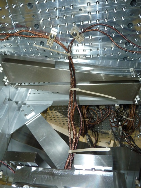
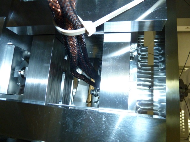
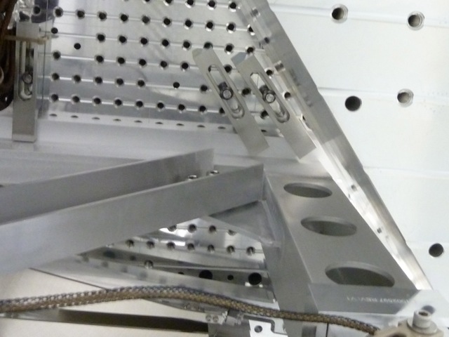
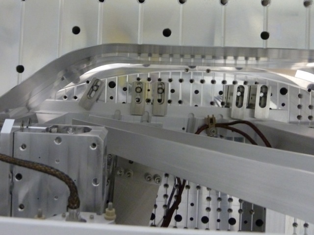
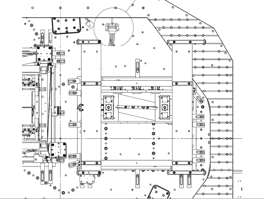
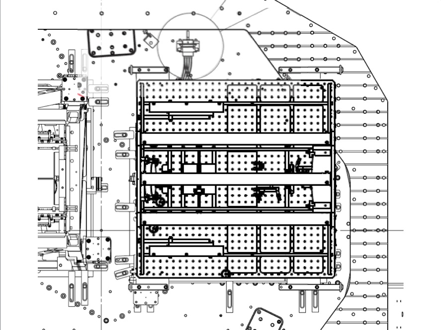
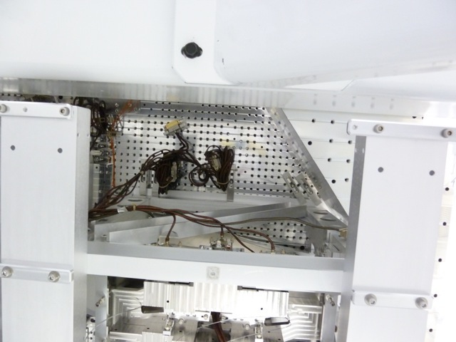
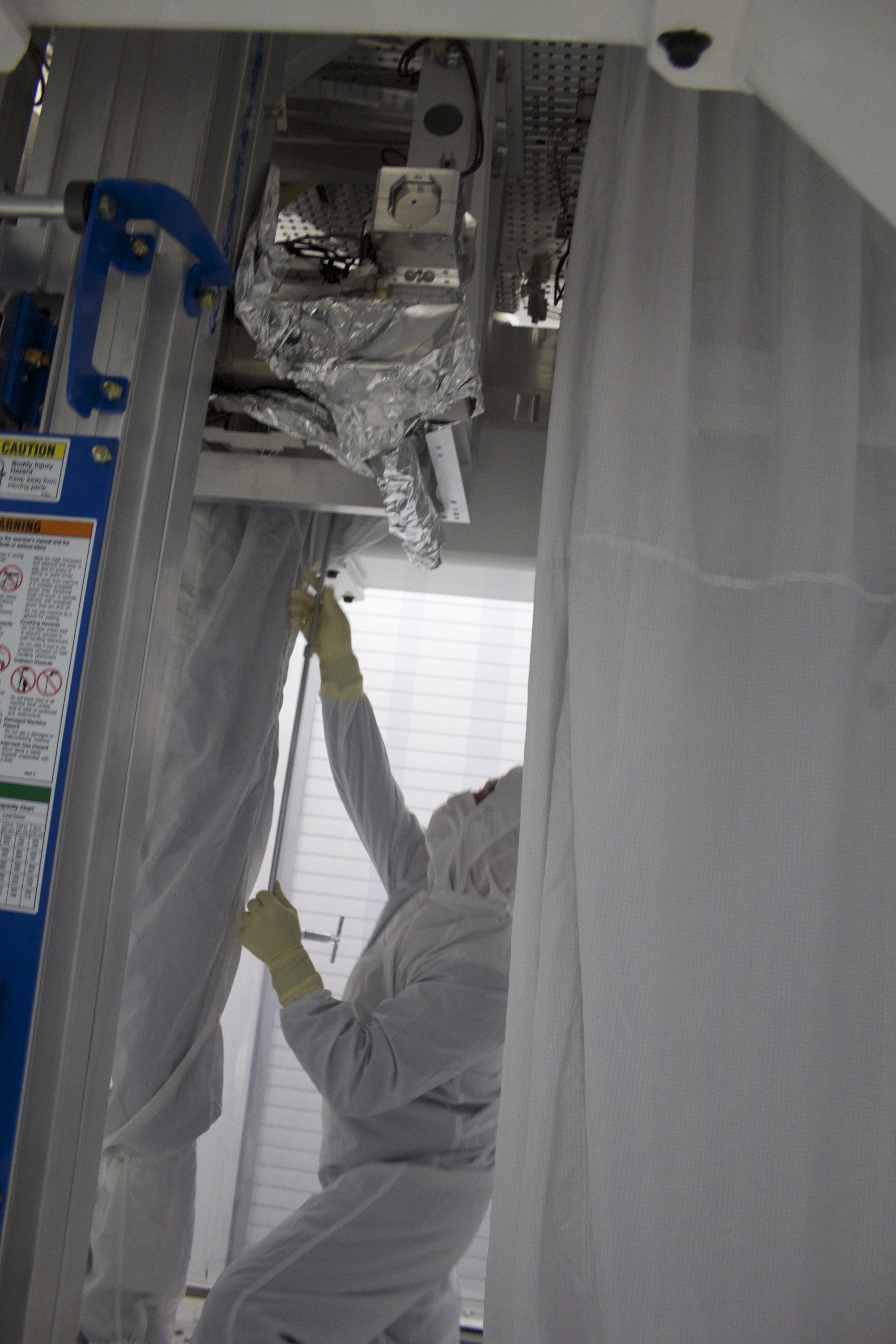
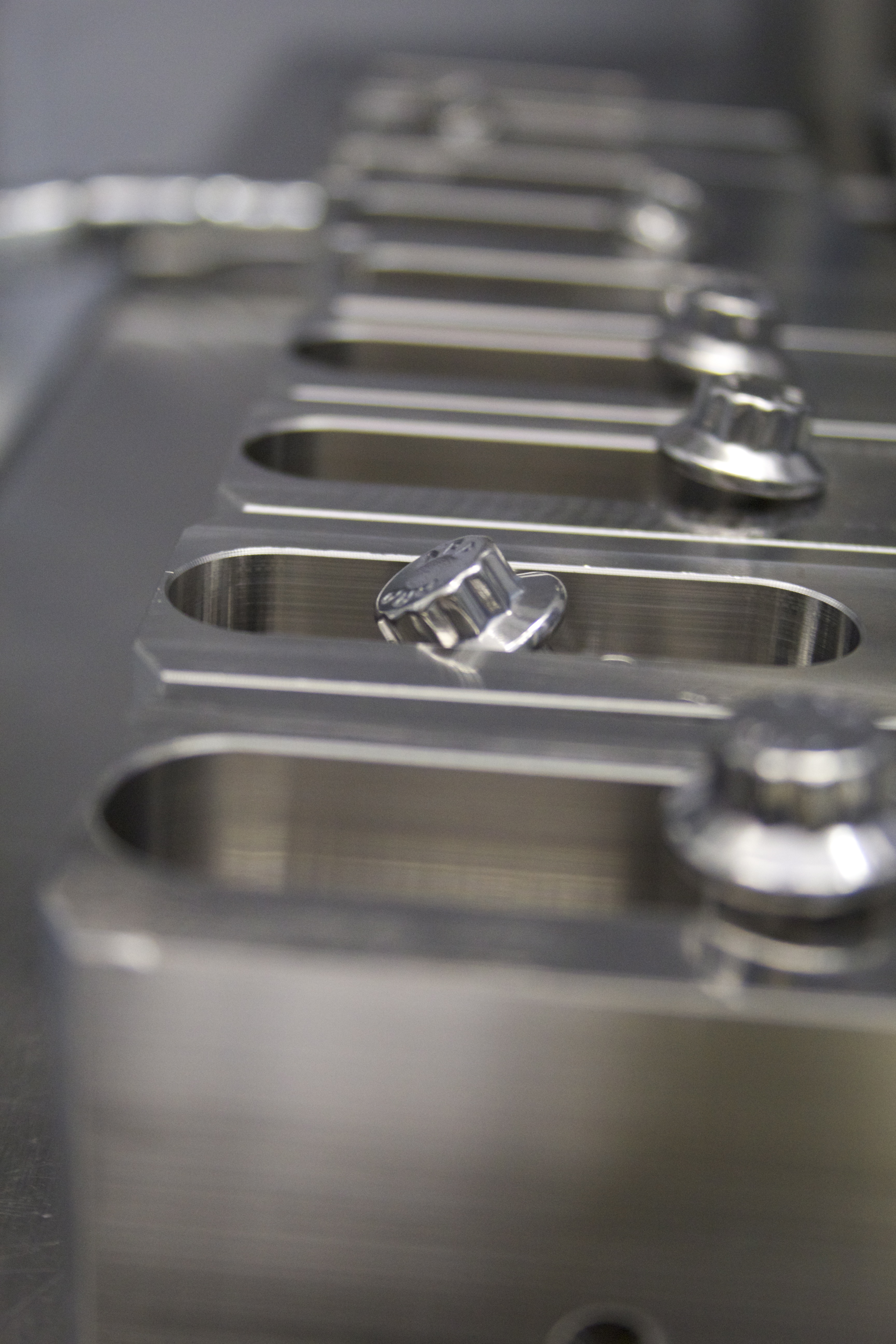
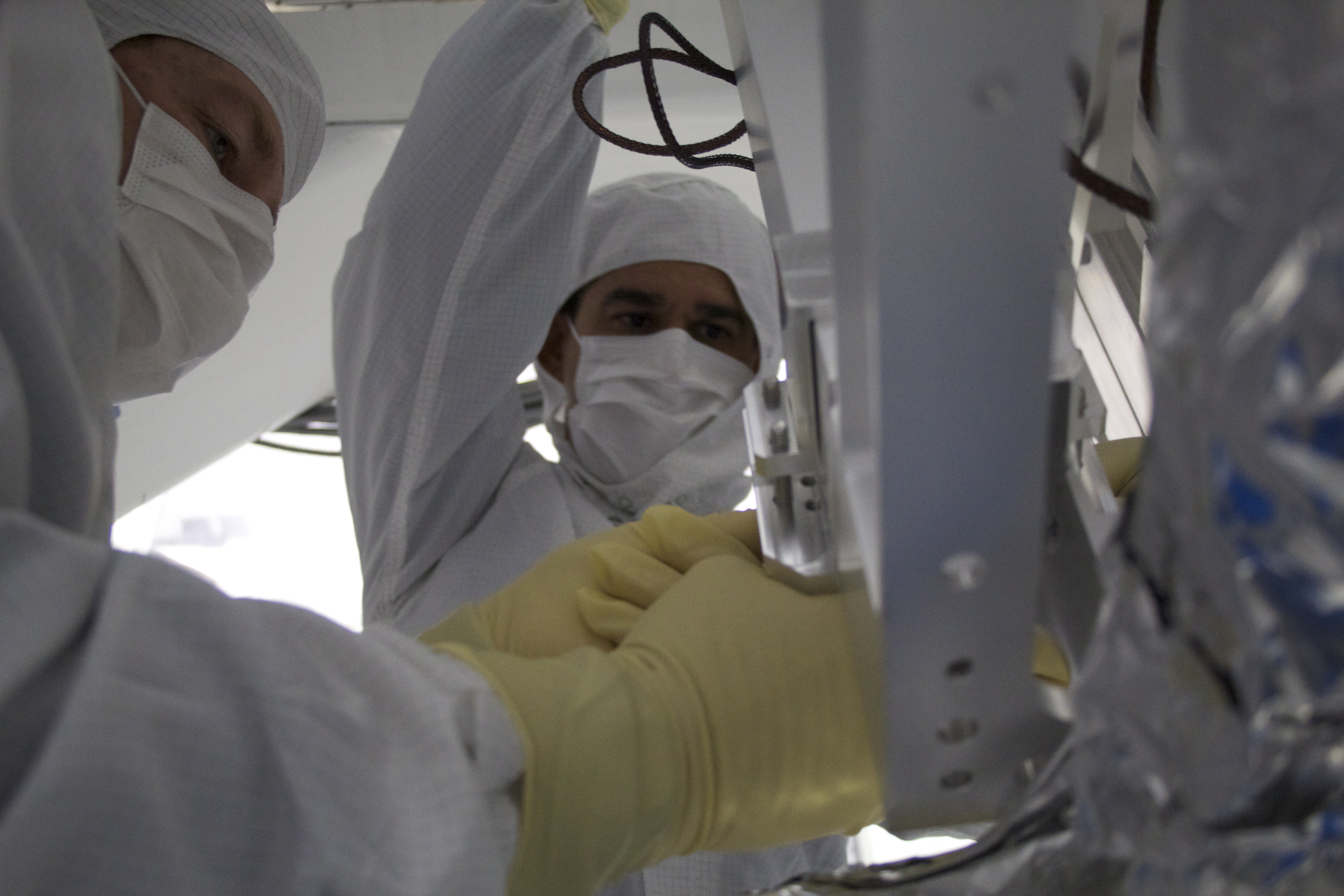
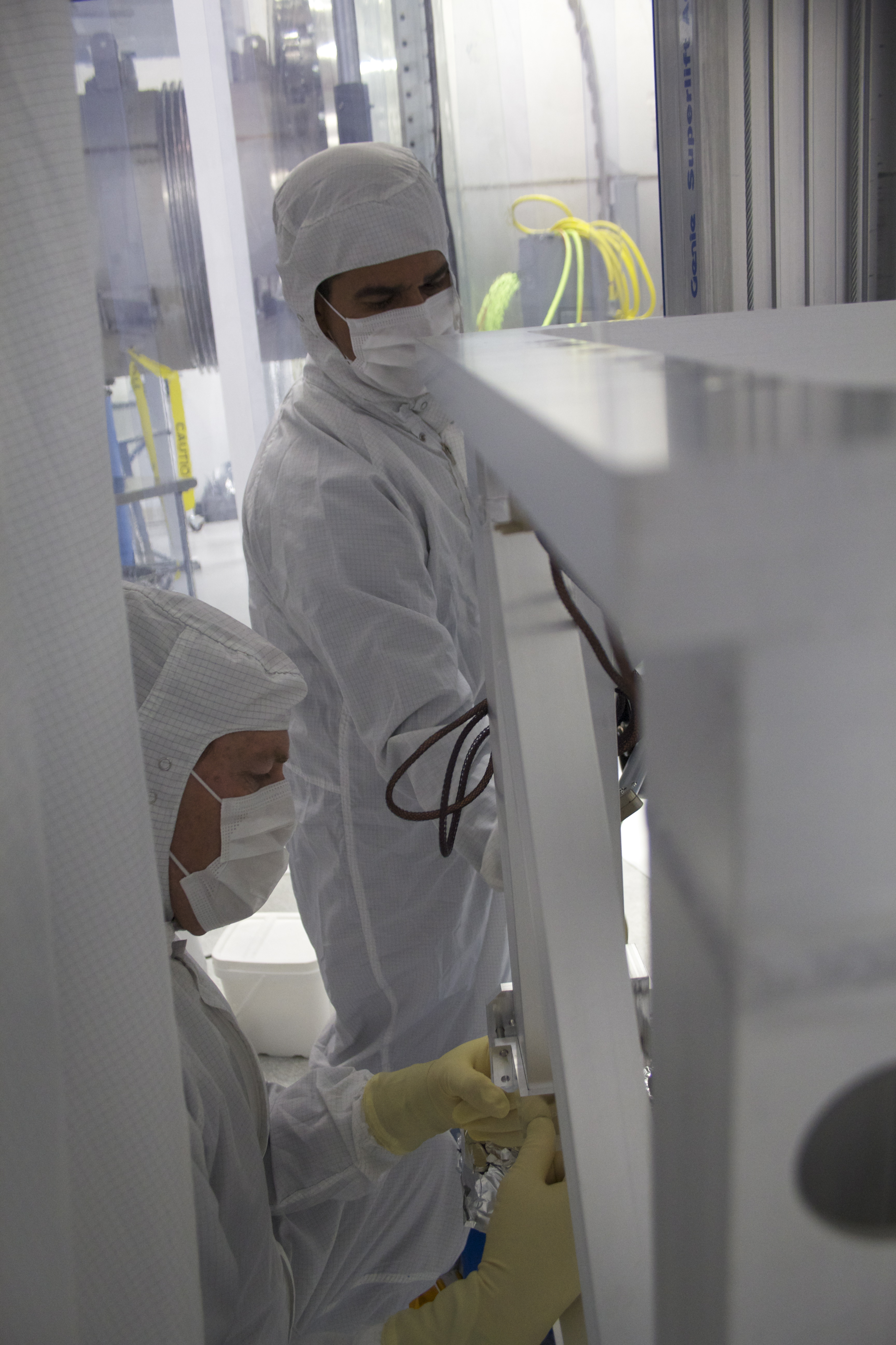
- Jeff, Corey, Andres, Cheryl Upper Structure: - OSEM cables dressed on the upper mass - cables that go through the upper mass are loosely bundled and tied to the ISI - dog clamps that were adjusted yesterday were torqued to spec. - telescope safety support beams were attached to the upper structure cube TO DO: - look at CB-3 cable bracket placement in D1300007-v2. I put in a separate alog. - redress upper mass cables after hanging the telescope. The upper mass is sitting high, so cables attached to it need to be adjusted after it's back in position. I worked on the cables coming through the upper mass in an attempt to have them not touch the upper mass and not rub against each other. Many attempts failed and Jeff's idea to tie them together is our only option for having them not touch the upper mass. ISC Table / Telescope: - Corey cleaned all the ISC table optics with Top Gun - he and I looked at a couple optics early in the day, and we both saw that the large particulate does come off pretty well, and the smaller particulate doesn't really budge - a familiar scene - threaded rods that hold the protective cover for the ISC optics are in C&B overnight - they are a good 4" longer than necessary, and the extra threaded rod gets scraped as the protective cover is installed and removed, so I asked to have the extra length removed and the parts recleaned class-B TO DO: - revisit the telescope optics with Top Gun to remove any particulate that might have fallen from the ISC table
In D1300007 CB-3 is placed on the -Y side of the TMSX upper structure. Betsy had moved the bracket, but after looking at the test stand today, I asked Jeff to install it in the original location. When I look up D1300007, Betsy has a redline drawing, and placed the bracket on the +X side of the TMS upper structure, but this is not accessible from below the upper structure once the ISC table/telescope is in place. Betsy's redline only claimed interference with the test stand, and there is no test stand interference for CB-3's original location. Maybe Betsy's redline drawing didn't fully explain her thinking. I sent her a text but didn't hear back. Late today, after installing the safety support beams on TMS, it's clear that the real issue with the original placement of CB-3 is that there is only about 6" to access the bracket from below, and access is between the telescope safety support beams (only 18" apart) - difficult and a risk to TMS. If the bracket must stay on the -Y side of the upper structure, my only suggestion is that moving CB-3 toward the QUAD cable brackets might allow slightly better access. Alternatively, maybe the +X side of the upper structure can be accessed through the structure, so would work? Either way, an alternative placement should be considered before bringing the TMS telescope under the ISI.
Kiwamu, Stefan We brought the IMC back to test the new FSS code. It seems to work as advertised - in Kiwamu's words: "fantastic". First we verified that we can manually lock the FSS, and then engage the autolocker without dropping lock. Next we verified that that if the temperature is close enough, but the FSS is not locked, the autolocker immediately tries state 2. This trick also seems to work often under normal operations. Next we locked the MC and kicked it as hard as we could (inverting the fast gain). This triggered the FSS autolocker to drop back to state 2 (with the temperature output frozen), but it came back up to state 4 after 1 sec. The simple IMC autolocker also seems to work reliably - 10sec after inverting the fast gain, we were back up. For the temp loop we also verified that the integrator hold in state 2 & 3, as well as the integrator clearing in state 0 works. I checked in all relevant files to svn - revision 5533: /opt/rtcds/userapps/release/psl/common/medm/PSL_FSS.adl /opt/rtcds/userapps/release/psl/common/models/pslfss.mdl /opt/rtcds/userapps/release/psl/common/src/fss/FSS_AUTOLOCKV2.c
In preparation of acceptance documentation, top mass PR2 transfer functions for phase 3b (in vacuum) have been measured during the night of August 5th 2013. Plots comparing model and previous measurements are attached below
(1) H1 undamped M1-M1 top mass transfer functions (in red) against hsts model (in blue)
(2) H1 damped M1-M1 top mass transfer functions (in red) against hsts model (in blue)
(3) H1 PR2 undamped phase 3a (pink) (in air, in chamber april 2013 ), H1 PR2 undamped phase 3b (cyan) (in vacuum, August 2013), L1 PR2 undamped phase 3a (orange) (in air June 2013)
Measurements are showing good agreement with previous data from LHO. Cross coupling in pitch is still present
At 2pm we transitioned the LAE to commisioning mode again. As Rick recommended we increased the temperature inside the room to match with the temperature in science mode operation. We reduced the power send to the PMc to the same level available in Low-Power-Mode (14W) and adjusted the PMC, ISS and FSS loop to that power level. We have not turned the high power oscillator off, yet, to perform a set of DBB measurements tomorrow morning. The DBB had to be realigned because of wrong settings in the snap file which was loaded after the power outage this weekend. I also adjusted the half-wave plate downstream of the PMC to send 1.5W in the IO path and checked that the power in front of the lower periscope mirror was only 0.94W. At 5pm I switched back to science mode operation of the LAE.
I also measured the power in transmission of the FSS available at the ALS, that is 12mW now.
08:30 Contractor arrived to work on vinyl flooring 09:09 Hugh and Greg going to HAM6 to work on HEPI 09:10 Cyrus going to end Y to work in computer racks 09:15 Corey going to end X to begin work for TMS install onto test stand 09:35 Travis going to LVEA test stand to work on ITM 11:22 Apollo craned a Genie lift over the Y arm 13:11 Water samples taken from site 13:22 Filiberto going to LVEA to run a power cable over HAM2 PSL environment channels occasionally briefly going invalid
Today we completed assembly of the work platform around BSC 3 with the exception of 1 section of handrail that interferes with some annulus piping on GV2. I have talked with Kyle and we should be able to remedy this quite easily. Transported a 3 step platform to end x for Cheryl to use in the clean room. Tyler worked in the machine shop, still working on parts for SUS (Betsy) and a small job for Filiberto. The flooring guys are approximately 85% complete with vinyl, they will come back tomorrow to weld joints and trim out.
Before lunch I got the sign off on the Optical Table position from IAS (Jason;) I expect you'll see an entry from him shortly. This was preceded by an elevation survey performed by myself and GregG: Our initial level had an 11mil runout about 4mils low per target (D1100398/E1000403). We did a couple small large Spring adjustments and finished at <8mils runout at -220.1mm average elevation Gz (0 error from spec.) After IAS was done, I activated the CPS, recorded locked positions and then unlocked the IAS. I repeated the lock and unlock recording the CPS all around. The largest change observed was <1200cts or 0.04mm, comfortably under our <1600 cts max lock/unlock change. WHAM6 has dummy payload on viton suitable for testing and is ready for doors. One final thing--conferring with Bubba/Apollo: I will lock the HEPI this afternoon and will not install HEPI electronics. Will keep the Dial Indicators in place to monitor HEPI position--please respect these.
The HEPI suspension is now locked. Other Chamber area preps have been completed.
Final measured XY position/yaw errors of WHAM6 ISI:
Last night, Christina Bogan transitioned to "Science Mode" in which all non-essential heat sources, lights, HVAC fans, etc. are shut down for her PSL characterization measurements at about 8PM. The attached plot (20 hours) shows the temperature transient that resulted. Note that two significant heat sources, the TTFSS and the ISS AOM driver reside at the south end of the table. To reduce the magnitude of the transient, we will try operating the room in Commissioning Mode at 4 to 5 deg. F higher temperature.
Attached are plots of dust counts requested from 4 PM August 26 to 4 PM August 27.
Attached are plots of dust counts requested from 4 PM August 25 to 4 PM August 26.
(Andres, Cheryl, Corey, Jeff)
Upper Mass Clamped To ISI
This morning the Upper Mass (already under the ISI on the Genie) was raised up on to the ISI (before that happened, Vibration Absorbers were moved to their correct positions) This was fairly straightforward. There were a few issues with a couple of clamps. Two clamps had to vary from the drawing (D0902163) because the ISI's Stage0 made installing the dog clamp's screws not possible. Then one of these screws also fell into a hole of Stage0 (think it can be fetched out by removing a dog clamp and using a tool to extract the screw). So, Upper Mass for all intents and purposes is clamped/torqued on the ISI.
Table/Telescope Staged for Cleaning & Install
Next up is rolling the "lower Assy" (i.e. Table & Telescope) under the Upper Mass and connecting Upper Mass SUS wires to the "lower mass". Before doing this, some tooling was staged, and then the Lower Assy was set up for inspecting/blowing dust off its optics. I have the Table/Telescope set up in the TMS Lab in such a way that it is in a dark area of the lab and it is easier to inspect the mirrors with flashlight. I went through a first round of blowing particles off the Telescope mirrors. I probably removed 40% of particles. But the remaining particles were pretty pesky, and I leave that for Cheryl to work on.
Once the optics are clean, we'll be ready to roll the Lower Assembly into the VEA (probably after lunch on Wed) & attach it to the Upper Mass.
[Whoops, made this entry last night (after adding more photos to the H1 EX TMS Resource Space), and this morning noticed Cheryl's entry. Sorry for reduncancy. Will keep up since I've updated a few things and posted pics.]
I installed and ran the new FSS autolocker code. Changes include: - Ability to engage the autolocker when the FSS is already locked - without killing the lock! - Three independent delay epics records for states 1, 2 and 3. Their names and for now reasonable operating values are: H1:PSL-FSS_AUTOLOCK_DELAY1 = 5 sec H1:PSL-FSS_AUTOLOCK_DELAY2 = 1 sec H1:PSL-FSS_AUTOLOCK_DELAY3 = 0.1 sec - On state 4 lock-loss, hold temperature output and try state 2 again (ramping up FSS gain) - A switching integrator in FM1 of the TEMP_LOOP. I loaded the following filters: FM1: p0:z0.05 (pole at 0Hz, zero at 0.05Hz, high frequency gain of 1 - this is the switchable integrator.) FM2: p500:g0.01 (pole at 500Hz, low frequency gain of 0.01). FM10 (not used) a copy of the old lowpass (the two new filters together are equal to the old lowpass, except that we now have a true integrator instead of a pole at 0.005Hz) The FM1 switchable integrator is turned off in state 0 and 1 to clear the integrator history. I didn't have a mode cleaner tonight, so we will have to check the fast-recovery feature through state 2 tomorrow. Other than that, the system behaved as advertised. Related items that will need to be checked in to the svn (I am holding off to test is a bit more before propagating it to LLO without warning.): /opt/rtcds/userapps/release/psl/common/medm/PSL_FSS.adl /opt/rtcds/userapps/release/psl/common/models/pslfss.mdl /opt/rtcds/userapps/release/psl/common/src/fss/FSS_AUTOLOCKV2.c (new file - already in svn) PS: On request from Christina I left the FSS and TEMP loop off overnight - the PSL temperature is still recovering form the fan speed change.
The last measurements have to be done when all the fans inside the PSL are off, so I switched into science mode for the night to do the measurements tomorrow morning. Afterwards I will switch backto commisioning mode to work inside the enclosure again.
For reference, here is NPRO characterization paper from Patrick and Benno. The laser currently installed in H1 is 1639F, i.e. "F" in the paper.