We tested a new scheme for IMC locking that is based on fast triggering on the IMC transmitted power. This allows discriminating against higher order modes, without lowering the feed-back gain. Our plan was to - acquire with the fast path (frequency feed-back) only - immediately engage the slow path (MC2 feed-back) once above the threshold - but avoid a large switching transient - and put some slow motion on the optic to make sure we see fringes. All that was achieved by - leaving the the slow path to MC2 on, but - have an additional 0.3Hz pole in the slow path. this puts some slow motion on MC2. - once triggered, this 0.3Hz pole is simply turned off, engaging the full feed-back without a transient. To implement this we had to make one minor change to the FILTBANK_TRIGGER.mdl library part: - our filter needed to be turned OFF on trigger (not the opposite) - we thus added an epics input named "_INVERT" (e.g. H1:LSC-MC_FM_TRIG_INVERT) to the library part - if "_INVERT" is 0 (the default), the behavior is unchanged from the previous model. - if "_INVERT" is ~0, the trigger fires if the input is below threshold. With this logic the IMC seems to grablock in less than 1 sec, reproducibly. The changes (both h1lsc and FILTBANK_TRIGGER.mdl were submitted to the svn (revision 5458).
Work on the OSB roof – Richard Work on the Optics Lab – Gregory TMS work at End X – Cheryl/Keita H2 PSL Enclosure work (local laser hazard ON/OFF) – Colin/Pablo
I looked into cross talk in the PEM Endevco boards and the Anti-Aliasing boards. For the Anti-Aliasing boards I directly injected a 5 Hz ramp signal and looked at 10Hz right before saturation. For the Endevco I installed an accelerometer on a shaker at 5 Hz and gradually increased it until just before saturation. The cross talk attenuations in the attached table are at 10 Hz.
After testing a known good channel on it, we determined that channel 3 of AA2 is bad.
[Stefan, Kiwamu]
Today Stefan reminded me that the WFS RTS library parts for its DC signal was updated in July 30th (see LLO alog 8061) and we haven't applied it at all in LHO. This update was for fixing the numbering of the four DC segments to match with that of the RF segments. Before appplying this updates, we wanted to make sure that this is the right thing to do. So for the reason we did a brief check on the existing WFSs, namely IMC WFSs on ITO2L. We intentionally misaligned the IMC REFL such that it hits only one of the four segments and did a block-and-unblock power modulation by hand to identify which segment responds. We went through all four segments on both WFS_A and WFS_B. Indeed the DC segments were in a wrong order of {4,3,2,1} while it is {1,2,3,4} in the RF segments. Indeed we need to correct it in the IMC realitme model although we haven't corrected it yet.
Looking at the l1asc model which uses the updated WFS library, we noticed that the labels of the tags associated with the DC library parts were incorrect. We probably need to talk to poeple in LLO to make sure that the update was done in a proper way.
VBO A is up and running again but the side effect is really high dust counts in the optic lab's vacuum oven room. For now the door to that room is closed, but hopefully the counts will drop soon. The fiberglass heat tape and insulation are the largest culprits.
We've tested a new tripod mounting system for the magnetometers with aims to decrease artifacts from motion of the magnetometer on the tripod. The iLIGO mounting scheme resulted in peaks in the magnetometer spectra that were not from real magnetic fields but from the magnetometer moving in the earth's field at tripod resonances. We tap tested both tripods to study their resonances and damping. The flagpole resonance of the current tripod is at 7.9 Hz. The new system, designed at Cal State Fullerton, is more damped and rigid. Attached is the power spectrum of both setups, side to side (see photo). The red trace is the magnetometer mounted on the current tripod, the blue trace is the magnetometer mounted on the Fullerton prototype tripod. The flagpole resonance of current tripod is seen at 7.9 Hz, the one place the blue Fullerton trace does not follow. Most other peaks seen are from nearby cleanroom fans and the expected 60 Hz. Terra, Robert
Two tripods in the photo - is the orange one the current or the Fullerton?
Orange is the Fullerton.
TMS ISC cables were attached to the mass using metal clamp with kapton tubing.
Took longer than we first thought because we had an interference with the screw tip of the clamp and the side of the blade, and had to experiment with shimming. Too thin a shim and your screw protrude more from the back and interfere with the blade. Too thick and your screw doesn't go all the way through the threaded hole of the bracket, and the thickness of the bracket seems to be smaller than 1/8, much thinner than you would expect from 1/4-20 thread.
Then the cables were attached to the cube rather than the ceiling using peek clamps. This is because we don't have a good tapped hole to mount cable clamps under Bosch frame. Once it is moved to the test end we'd have more options, but in the mean time this should be good.
The top mass was rebalanced, table cloth was readjusted to maximize the clearance (the tolerance is extremely tight), BOSEMs were repositioned but we couldn't proceed as there was a trouble attaching the side BOSEM to the new mounting plate (see another alog).
In parallel with side BOSEM effort, we still need to mount the dummy feed through to the Bosch frame, put the BOSEM cables on, and set the height of the BOSEMs correctly, which looks like half day's work, before we can test the SUS.
pictures: https://ligoimages.mit.edu/?c=1361
Side BOSEM mounting plate that came out of the oven today didn't have tapped holes and we couldn't mount BOSEM on it.
According to https://dcc.ligo.org/d060323 it has four 8-32 tapped holes, looks as if the shop just drilled holes for the tap and then forgot tapping.
Will talk to Bubba and Tylor to see if they can dry tap (we need four such holes per plate). No SUS test today.
Robert reported ADC issues with the PEM model in the corner station. I restarted the h1peml0 and h1iopoaf0 models and he reports the problem has been resolved.
I re-imported the l1asc.mdl to Hanford and compiled it. Changes: - L1->H1 globally - l1 to h1 globally - LLO to LHO globally - replaced the PSL IPC with a simple epics input (temporary, due to missing hardware). Recompiling and running worked, but revealed a bug in the RTCDS code: - the kill script got stuck in the burt safe command. Temporary fix: replace grep h1asc with grep "h1asc " Next I will start adding the inital alignment stuff for the arms.
Had to restart these to restore communications.
- Works at EY
Apollo: ask Bubba
Richard ask him
- Works at EX
Keita (ISI) getting ready for SUS
- Works at LVEA
Michael, Hugh: ... some HAM are offset by several mm and that can cause problems with the mode matching ... (talk to them)
Arnaud TF
- Michael gave a tour to a PNNL group
- PRAXAIR came around 9:30AM, left around 11:40AM
- (14:20) John and a group of contractors went to the roof
- Mark Hankel and the fire department were checking fire extinguishers
- DUST at Bake-Out was very high (15000 for 300nm, 5000 for 500nm) today. Patrick told me that Greg was working inside. John is aware of the situation.
Attached are plots of dust counts requested from 4 PM August 13 to 4 PM August 14.
Terra Hardwick, Vinny Roma, Robert, Stefan)
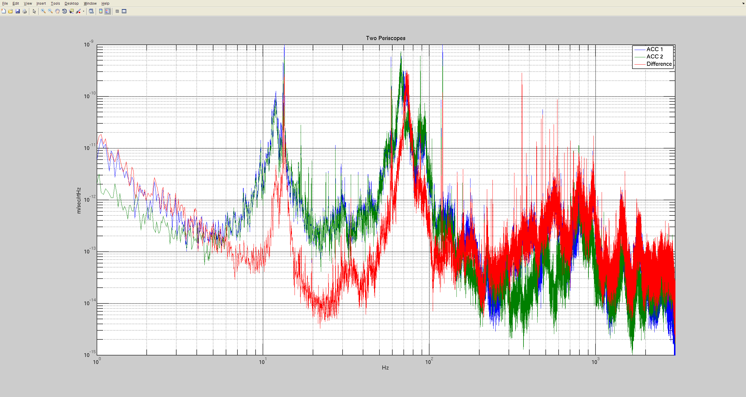
We hat 2 accelerometers mounted on the two pryramid-shaped periscopes on ISCT1 that are in the ALS beam path.
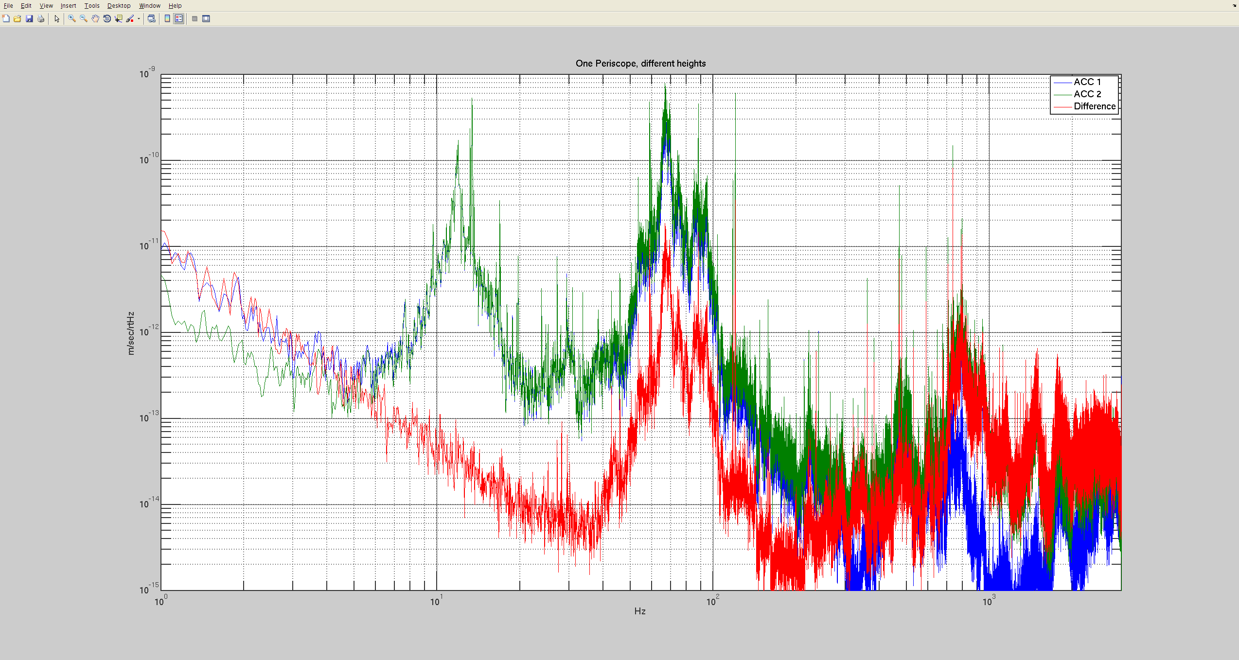
Below are plots of the velocity spectra for each accelerometer, as well as for the difference. No separate calibration was applied - we simply took the difference of the raw data. However, as can be seen from plot 3, the two accelerometers seem to be matched to better than 1%.
Plot 1 shows the of periscope 1 vs periscope 2 spectra. Note that the highest peak is just below 70Hz, but common in both periscopes - the two periscopes seem to be locked together. The peak just above 70Hz however is the dominant one in the difference spectrum. It is also the one that shows up in the HIFOY spectra.
Plot 2 shows the two accelerometers mounted on the same periscope (the middle one that carries the green beam from x and y arm). The accelerometers were mounted at a slightly different height, about a 3 inch appart, corresponding to a setup with different mirrors mounted on top of the periscope. Note that we get about a factor of 10 suppression.
Plot 3 again has both accelerometers mounted on the middle periscope, but at the same height, i.e. simulating a situation with all three beams hitting the same top periscope mirror. The suppression factor is now too good to believe. This suggests that if possible, using the same top mirror for all 3 beams would be beneficial.
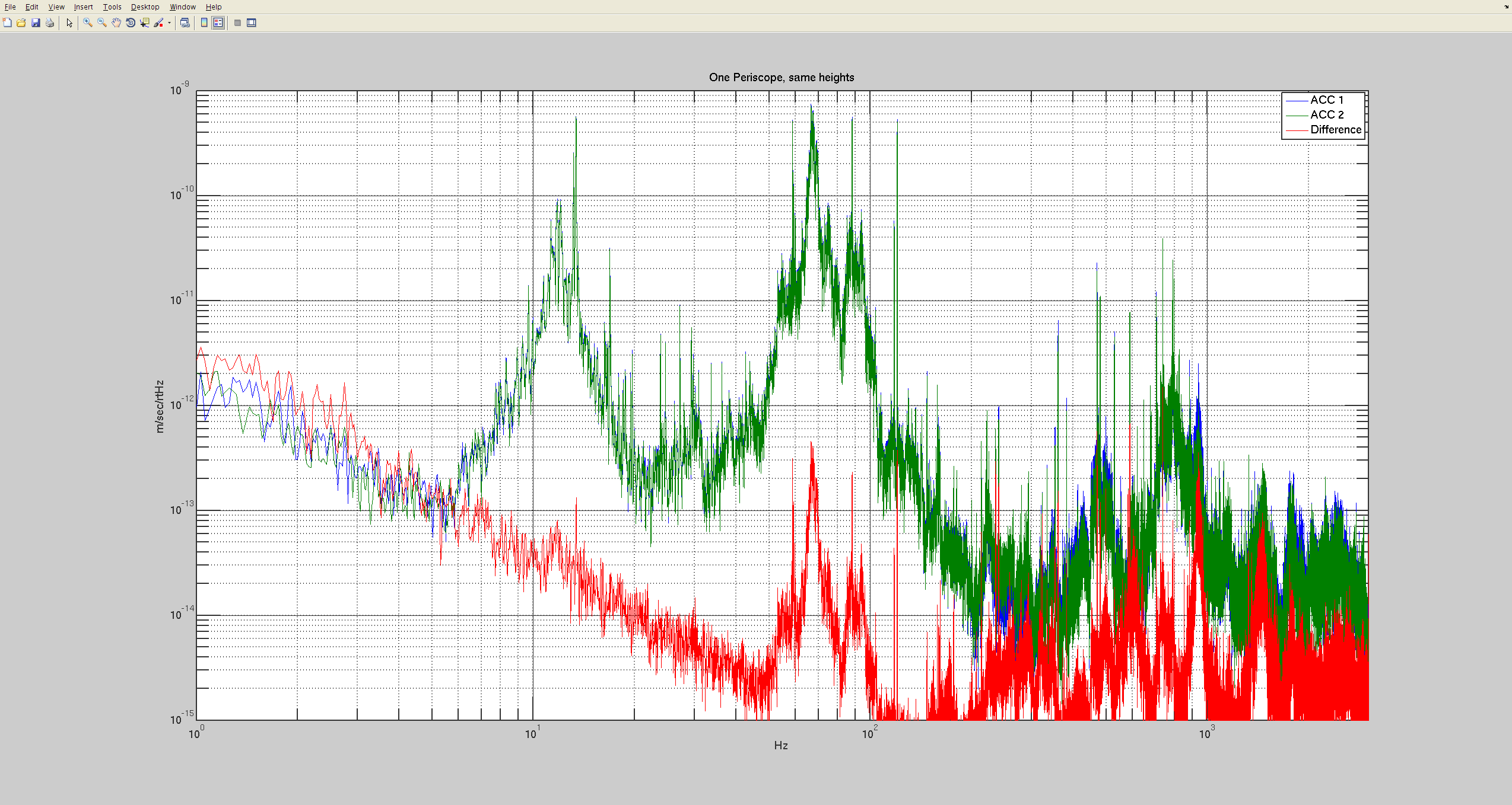
One warning about the accelerometer mounting: they were attached directly to the periscope. having two different mirror mounts can make the situation slightly worse. This again would suggest that using a single top mirror would help.
All plorts are calibrated in m/sec/rtHz.
Kyle, Gerardo Today, after John had notified Rai of our intent, we applied a few drops of Vacseal (SPI Supplies, Space Environment Laboratories, original formula 0502-AB) to the top of the previously identified leaking 1.33 CFF on GV6 (North gate annulus port). The leak seams to be fixed now.