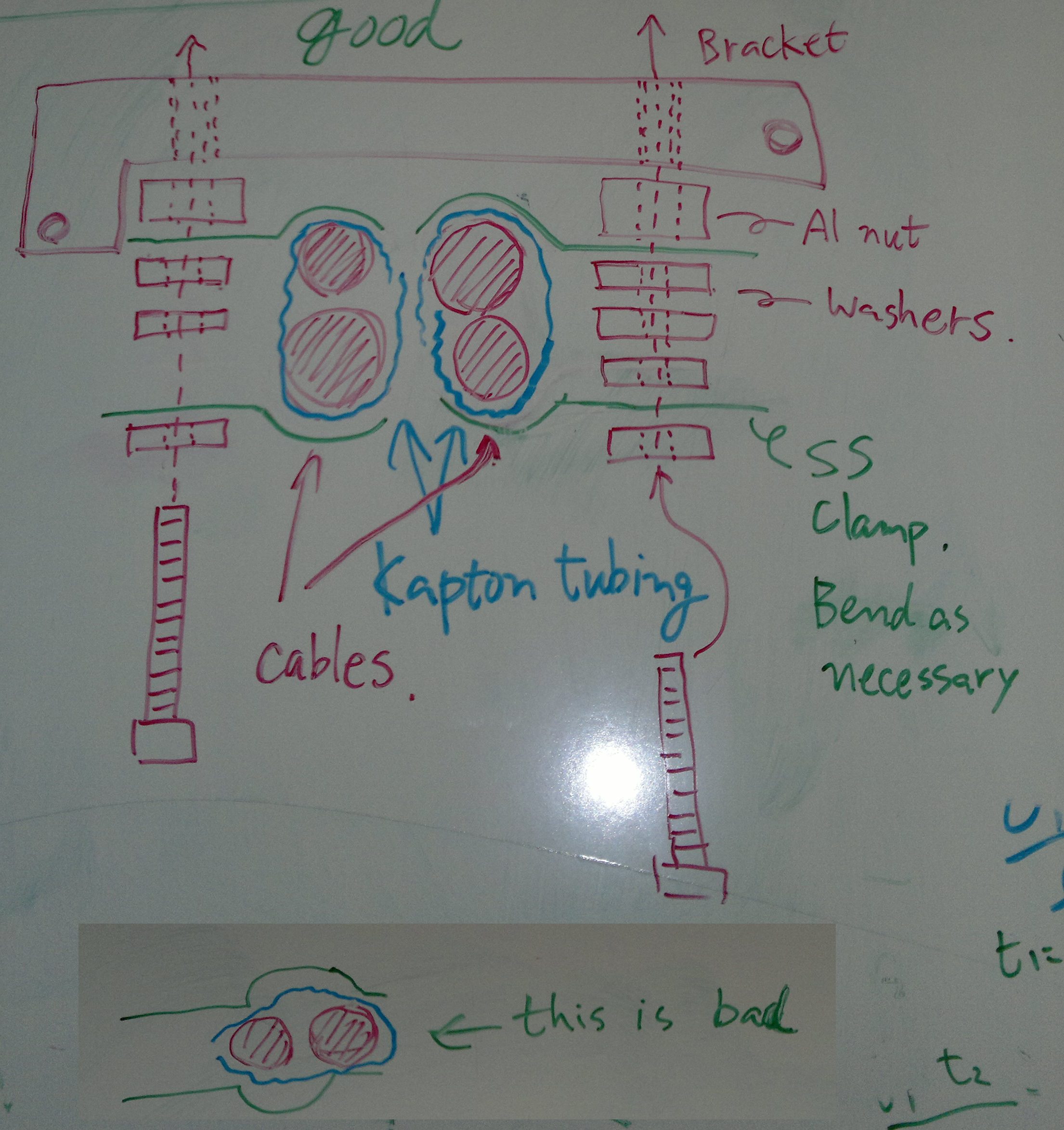
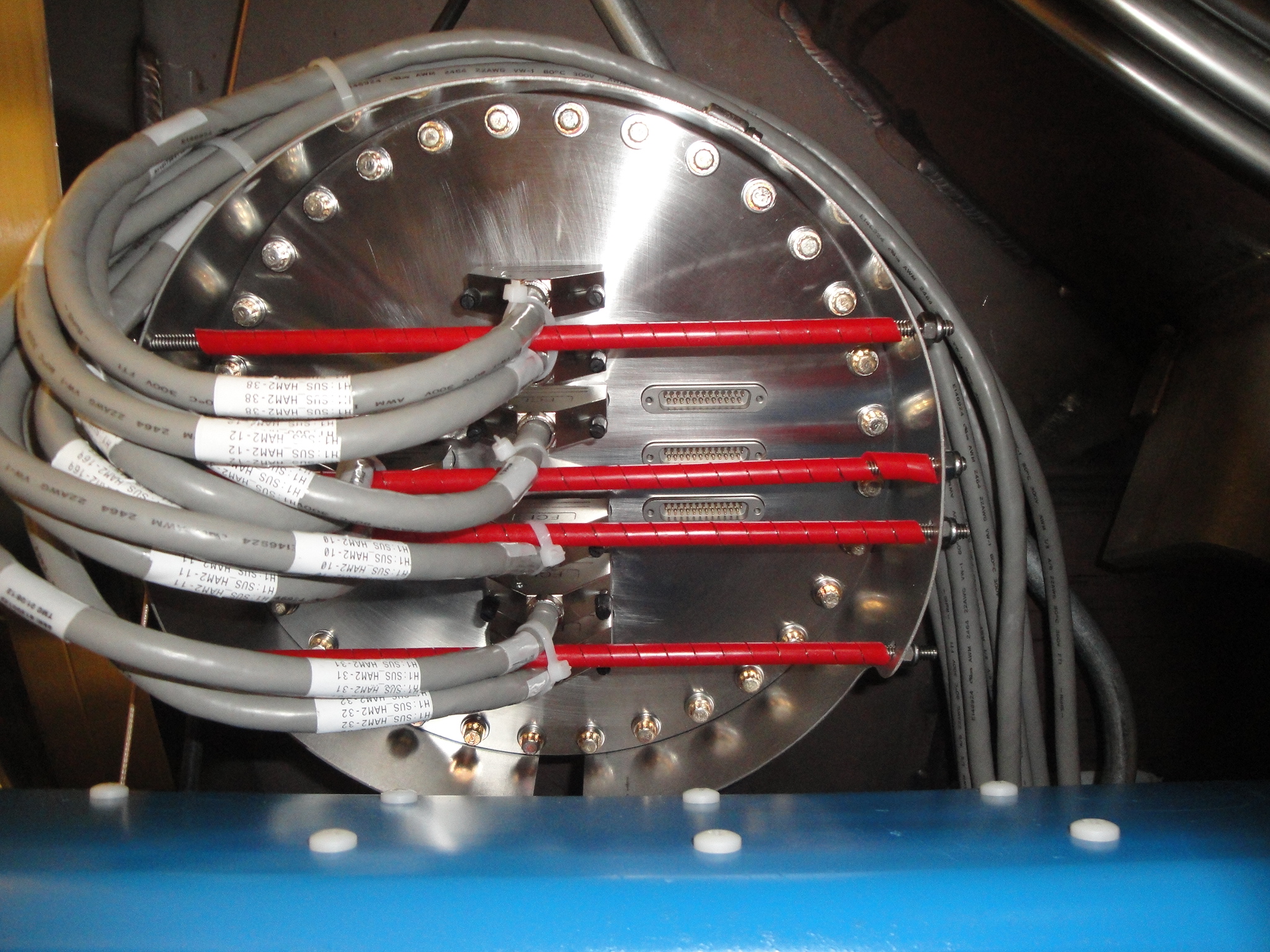
Spent an hour to play with the cable clamp bracket, and improved on Cheryl's idea to use metal clamps with kapton tubings (first picture).
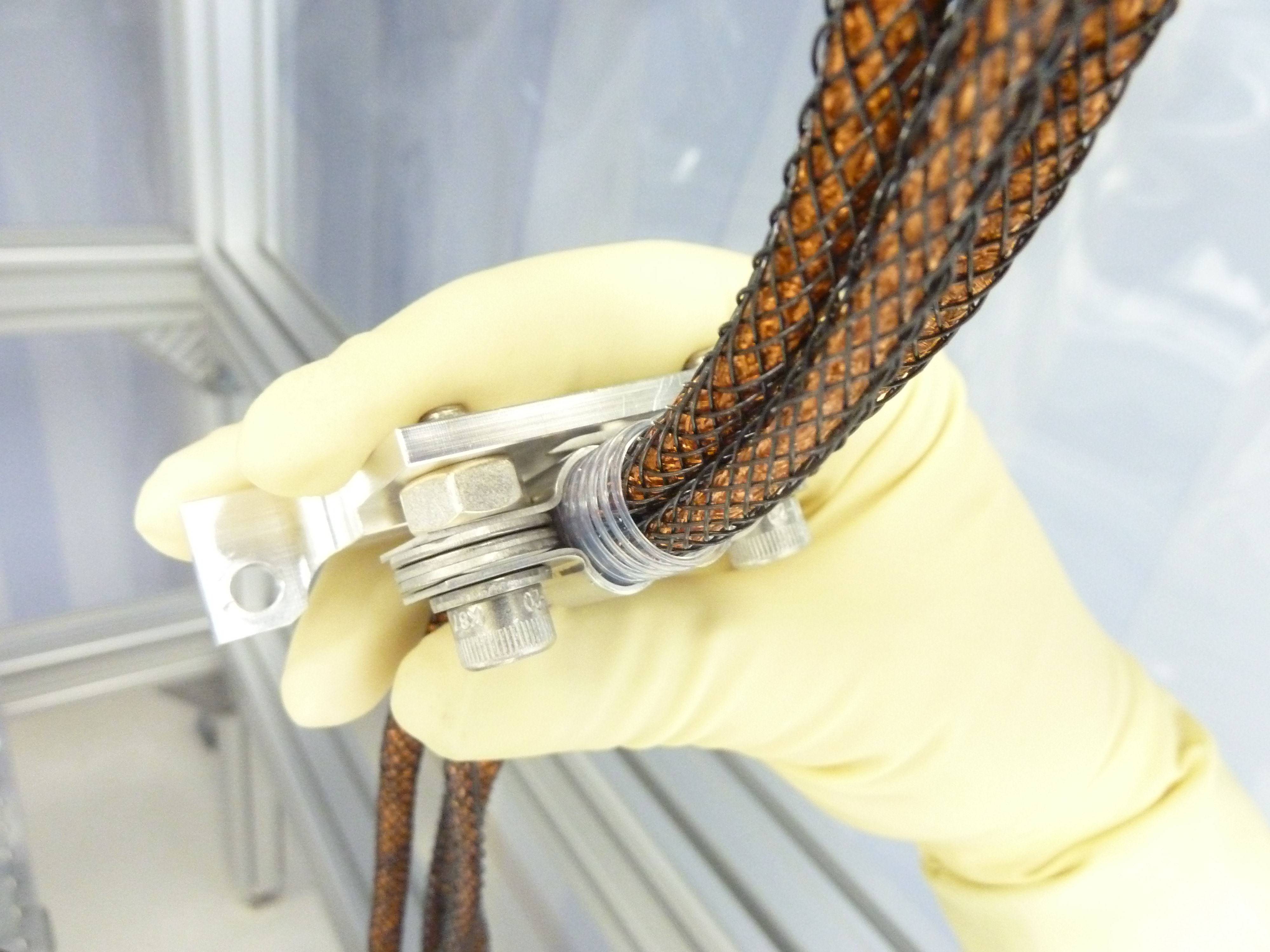
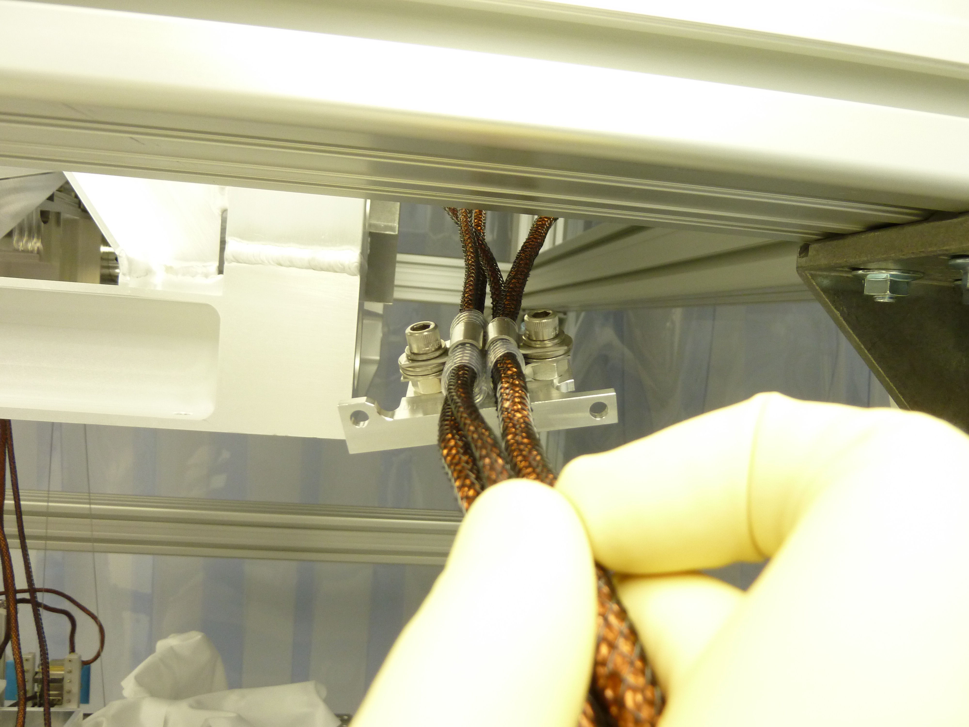
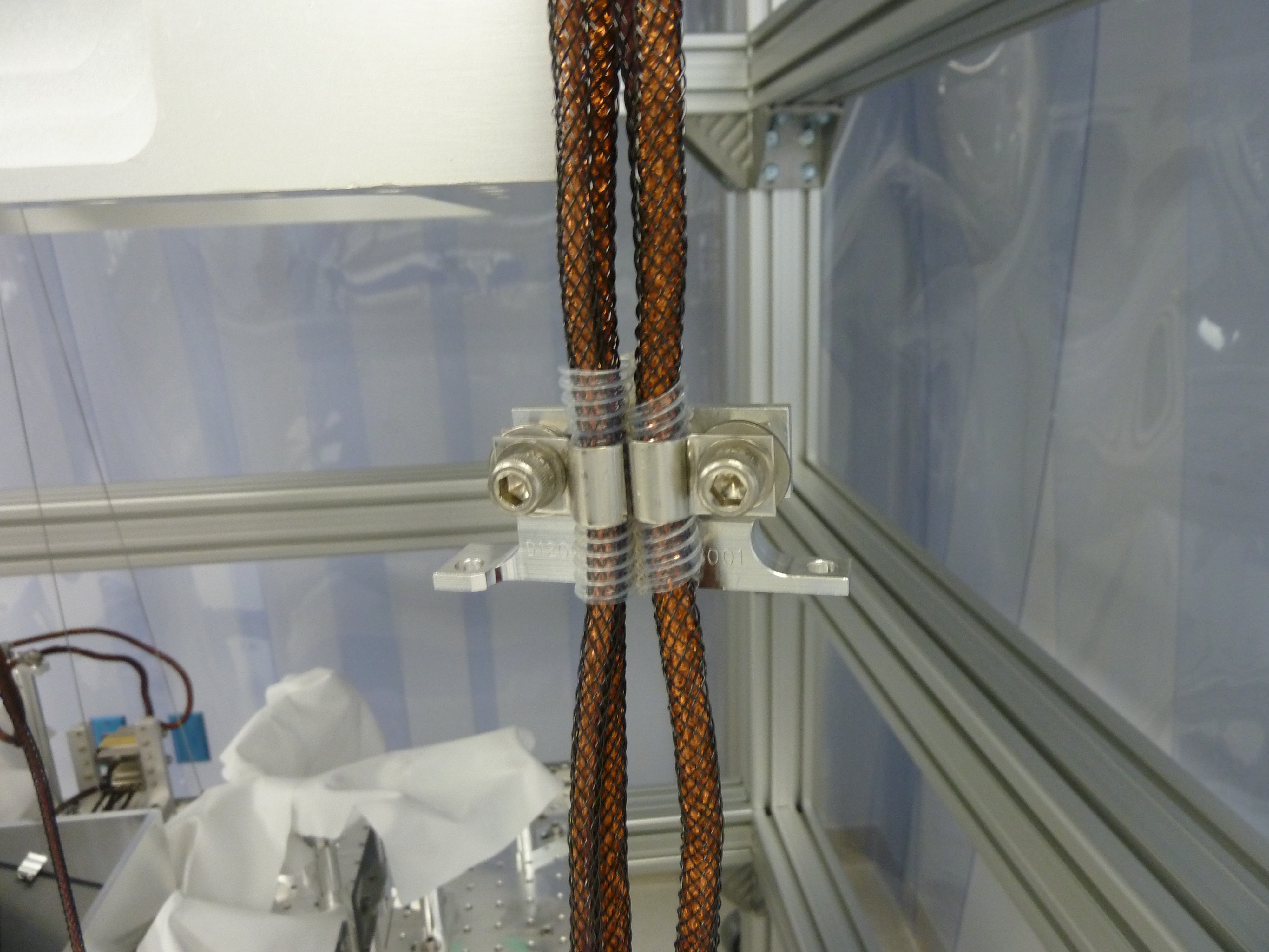
One D1000921 (thicker, for pico, beam diverters) and one D1000921 (thinner, for QPDs) are wrapped with kapton tubing and clamped using a pair of metal hold down clamps (second picture). Two such pairs are made (third picture) and they sit next to each other. I also tried making thin-thin and thick-thick pair, but it didn't work well. Thin--thin is easy to rotate between the clamps and goes to "bad" position in the first picture easily, losing any clamping pressure.
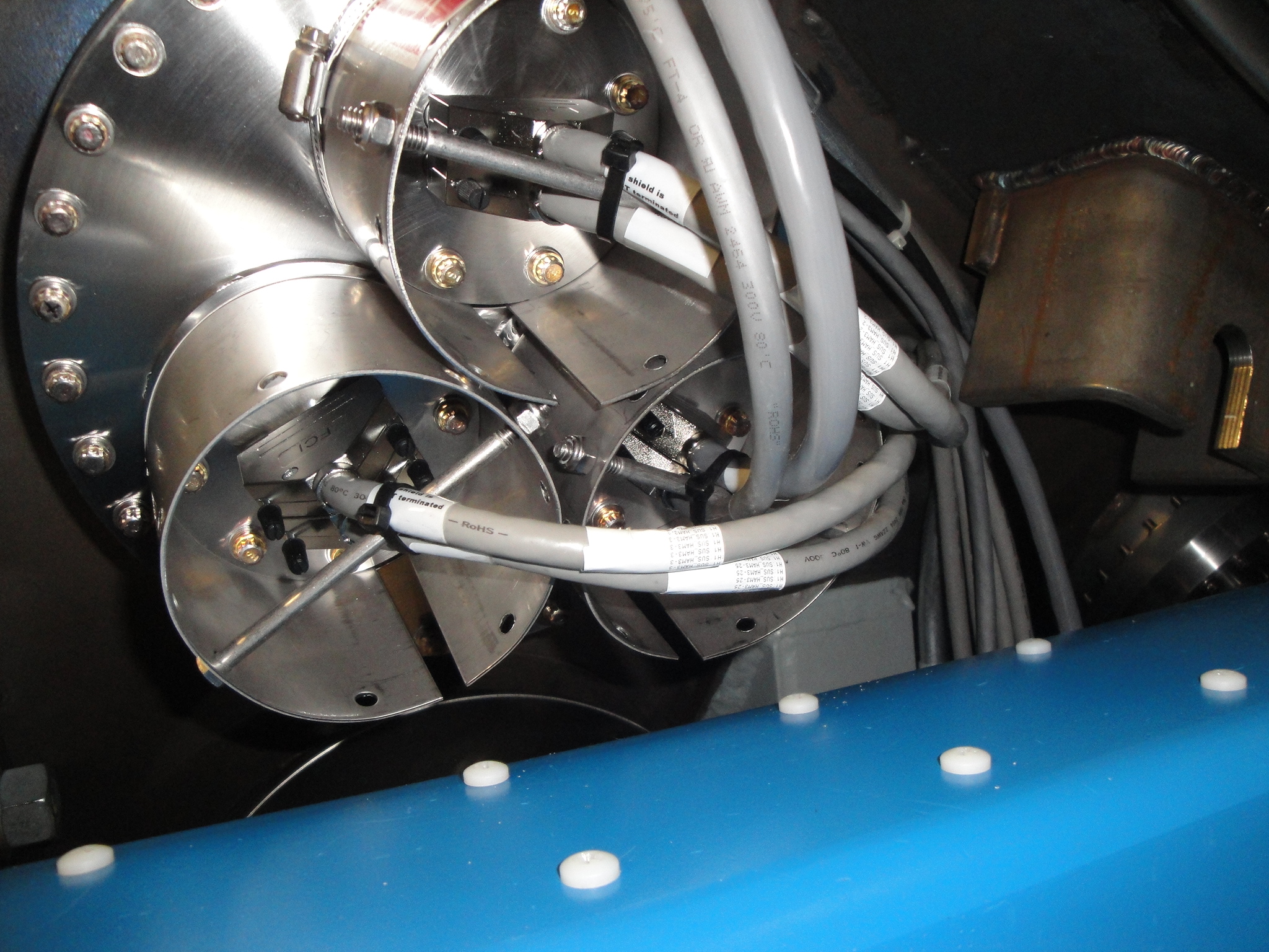
Extra care should be taken to align things properly, and the number of washers should be chosen such that everything is snug but not too tight when the bolts are tightened. When you pull the cable it should slide inside the tubing, but it should not slide on its own.
With too few washers, it's easy to put too much pressure on the cables which promotes short circuits as the soft teflon insulation is broken. With too many washers, even if it feels OK at first, it is easy to rotate the cables in the clamps so the cable pair goes to "this is bad" position in the first attachment and the thinner cable becomes loose.
Note that I'm abusing a 1/4-20 aluminum nut as a poor man's washer. This is because the normal washers we have is too big and interferes with the curved part of the metal clamps, and we have a limited supply of smaller washers. It's working OK, when I tightened the bolts there's no loose thing.
This is just a test run by one person using the wrong end of the cables for ease of access, we'll do the real run tomorrow.
Dan worked on the MSR SATABOY and its associated Sun/Oracle server. He upgraded all firmware and moved hardware around. The disk system is back online and no data was lost.
We have restarted h1fw1 and h1nds1 and frames are being written again. The data gap on h1fw0 is
aug 13 23:31
aug 14 17:04
This afternoon Jim moved the default NDS from h1nds1 to h1nds0. We will keep it this way overnight and swap back tomorrow if h1fw1 continues to be stable.
- H2 enclosure on/off laser hazard today - diode room dust monitor checked - dust monitors restarted - disk failure on FW1 - H1 PSL ENV channels fixed
The default NDS server has been changed to h1nds0 while frame writer 1 is down. This takes effect for any new shell or matlab session started after 16:03 PDT today.
The work platform assembly was completed by the Apollo crew. They also transported the balance of the FFUs for the chamber cleanroom from the OSB High Bay to Y end: the FFUs are currently in the outer bay. Hand rails got wiped down and moved into the VEA. Scott worked with Hugh on HAM6 this afternoon. I spent some time working on the "curtain problem":we have lots of curtains but very few of the correct length for a chamber cleanroom. I think I have a path forward but would like to discuss it with Bubba first.
I have temporarily swapped the (H-V) L4C cables of the HEPI in corner 2 and 4.
Several updates on matlab scripts modifications I recently made during data processing
1- generate_QUAD_Model_Production.m. Produces a matlab model for damped and undamped quad suspension (/ligo/svncommon/SusSVN/sus/trunk/QUAD/Common/MatlabTools/QuadModel_Production)
The filter file used in the script to compute the modeled closed loop was out of date from the filters installed on our quads, so I updated it with the most recent damping filters : "dampingfilters_QUAD_2013-06-14.mat" living in /ligo/svncommon/SusSVN/sus/trunk/QUAD/Common/FilterDesign/MatFiles
design_damping_QUAD_20130614.m (that creates dampingfilters_QUAD_2013-06-14.mat) won't work if susTag is set to "L1:SUS-ETMY" since there's no 'etmy' variable in the ISI2SUS_projection_file.mat
2-plotquad_matlabtfs.m. Processes the measurements and plots them against our model (/ligo/svncommon/SusSVN/sus/trunk/QUAD/Common/MatlabTools)
The option of plotting the measurements with the damping active against the closed loop model has been added to the script, with a new flag "isDamped=true/false" at the beginning of the script
3-Matlab_TFs.m. Launches automated transfer functions (/ligo/svncommon/SusSVN/sus/trunk/Common/MatlabTools/SchroederPhaseTools)
The script has been modified in order to take transfer functions on several suspensions at the same time. The drive signal txt file used by awgstream to send an excitation is now suspension specific, as well as the diary file. Those two files were creating conflicts and error messages when two similar tf scripts were beeing run at the same time.
Also, in order to make the script easier to read, and for future debugging purposes, I moved the sensor and actuator channel list out of the code, and packed it in a subfunction "generate_channel_list.m" located in /ligo/svncommon/SusSVN/sus/trunk/Common/MatlabTools/SchroederPhaseTools/
4-collect_schroeder_TF_v9DQ_sma.m. Subfunction of Matlab_TFs.m. It creates a schroeder phased drive signal
From now, when Matlab_TFs.m is ran, the one time excitation signal, as well as the full drive signal will be displayed and plotted, as a function of time before the signal is sent to the DAC.
Yesterday this IOC lost communication to the dust monitor in the diode room. I restarted it today and it has reconnected. I suspect the Comtrol serial to Ethernet converter (10.105.0.100) is on the network switch that was remounted yesterday.
The SATABOY QFS disk system used by h1fw1 and h1nds1 suffered a failure at 23:31 last night local time. I have turned off h1fw1 while we investigate the problem.
Please use h1nds0 for archived data until this problem has been resolved. h1nds1 will only support real time data.
Attached are plots of dust counts requested from 4 PM August 12 to 4 PM August 13.
Attached are plots of dust counts requested from 4 PM August 11 to 4 PM August 12.
Out of the 4 DoF (arm optical axis pos and angle, green input beam pos and angle, 2x for pitch and yaw not counted), 3 DoF will likely need a frequent initial alignment - the input beam position at the ETM is the one DoF that remains fixed. Below is a short description of the suggested alignment loops. Attached is a draft RTCDS model block for e.g. X-arm pitch (we need 4 of them for X/Y P/Y). Signals to be demodulated: L: cavity PDH length error signal (green) R: cavity reflected power (green) T: cavity transmitted power (green) Actuation basis (in rad): (ITM, ETM, TMS) g-factors: g1=1-L/R1; R1= RoC of ITM g2=1-L/R2; R2= RoC of ETM Dither drive frequencies: f1: ITM dither frequency fT: TMS dither frequency Control loops: 1) Fix ITM actuation node L --->x ---> CTRL_FILT -----> (g1,1,1) ^ | f1 Remark: - Actuation at 1.65-2Hz or above 4Hz seems possible in pitch - Pitch centering offset at 1.7Hz: ~2.3mm (slightly freq. dependent) - Pitch centering offset above 4Hz: ~4.7mm - Could provide a slight additional length drive to compensate this offset - no such issues for yaw - Actuation leaves the following quantities unchanged: - arm axis position on ETM - angle between arm axis and input beam 2) Input beam to arm axis angle overlap at ETM focal point R or T ---> x ---> CTRL_FILT -----> (1,g2,g2) ^ | f1 Remark: - Actuation leaves the following quantities unchanged: - arm axis position on ITM - arm axis to input beam separation at ETM focal point - input beam position at ETM (trivial) 3) Input beam to arm axis angle overlap at ETM R or T ----> x ---> CTRL_FILT -----> (0,0,1) ^ | fT Remark: - Actuation leaves the following quantities unchanged: - arm axis position and angle - input beam position at ETM (trivial) Alternatives: - GigE camera centering on ITM (instead of 1) - ETM dither possible, but due to the steep drop-off of the Quad actuation, I expect reasonable drive amplitudes (producing a decent dip in power buildup) to only be possible at very low frequencies. As a result, since the dither frequency separation dictates the achievable bandwidth, it might be difficult to run all dither loops at the same time. General Remarks: - The dither drive is done in the optics basis, because any other basis would require significant attention to the relative phase of different actuation functions. - To be able to run the loops in sequence, an orthogonal actuation function is desirable. - repeat procedure of X- and Y -arm, pitch and yaw - Once both arms are aligned, turn this feed-back off.
(Sheila, Stefan) Looking at the trend data (mostly OSEMS) of PR3 PR2 and PRM, it looks like they can drift by up to about 10urad in both pitch and yaw over the course of several days. We were curious what that means for initial alignment requirements. So we put together a ray transfer matrix model based on LIGO-T0900043: “Optical Layout and Parameters for the Advanced LIGO Cavities”. With that we looked at how much the beam spot on the ETMs would move given the 10urad drift (the factors of 2 are due to reflection on the mirror): PR3: 2x 4.0 mm/urad * 10urad ~ 80mm (compare to beam spot size of w=62mm - motion too big) PR2: 2x 0.44mm/urad * 10urad ~ 9mm PRM: 7 um/urad * 10urad ~ 0.07mm (tiny!) SO: - PRM will be just fine, and won't need any daily realignment. - PR2 seems to be borderline - probably good enough for locking, but might need the occasional tweak. - PR3 (&BS) will definitely need an alignment. The logical place for this would be during the green locking - we might want to add green QPDs on ISCT1. Similar conclusions will hold for the SRC (once its installed). Here an initial tweak-up of SR3 can be done with the AS_DC QUAD on HAM6.
Work for today:
- Kiwamu and Karen, PSL enclosure/room cleaning, and PSL switched from Science to commisioning.
- Hugh, cable strain relieve at HAM2 and HAM3.
- Richard, end station cleanroom work, electrical.
- Jodi and Bubba, end station work.
- Hugh, to HAM6 work.
- David, DAQ reboot.
- Cyrus, network switch re-rack.
Deliveries/vendors:
- Praxair, LN2 delivery to CP1, level now at 93.2.
- Unifirst, change out mats.
Set the HAM6 Optical Table to -220.1mm Gz per E1000403 & D1100398. Used Mon 802. The table started about 1 to 1.5mm low. Finished at average -220.3 +-0.2mm; still need to do horizontal alignment so this is close enough on the vertical for now.
We locked the ISI to do this measurement & adjustment. It remains locked at this time.
Went through all the Feed Thrus on these chambers and added strain relief. This consists of the rod (bolt, all-thread) & zip tie. I also fussed with cable routing some to get cables off the HEPI Crossbeams (Floating.) I had to power down the HAM2 CPS racks for a time. Couple photo attached if you care to see what I'm talking about.
I care - very nice.
The workmen from Craftsman arrived this morning to install the balance of the flooring at Y End. However, there was not enough flooring on-site to complete the task. (Yes, we had checked before hand but the guy who really knew the answer was on vacation...) The Craftsman work crew was called off and additional flooring ordered. The ETA for the flooring to Seattle is 23 Aug but Craftsman will expedite if possible. In the meantime, we will work on populating the chamber cleanroom, assembling the work platform and modifying the CPB cleanroom.
Created H0EDCU_TIDAL.ini, added to DAQ
Restarted all DAQ systems newly built against RCG2.7.1. Added all DCU systems back into DAQ exceeding initial 85 DCU limit. Verified that dataValid flag in frames are correct (unity no longer written). Patrick verified no corruption of DUST channels.
New broadcaster channel list installed (list from JZ).
Create first version of h1pemex model (copy of h1pemey). Built model against RCG2.7.1 (all other models still at 2.7). Started model and added to DAQ.
H1EDCU_DAQ.ini expanded to include new DAQ PV channels. Created DC0 Front end channel list from rtsystab list.