After much anticipation, we finally receive a pair of bought Ag-coated mirrors from Newport. Within seconds we were able to tell these guys were much better ("order(s) of magnitude better", says Keita) than any other TMS mirrors used for LIGO.
One of them only had a few "spots" which could be seen from the front with light behind it. And this one had no "cloudiness" observed with many other mirrors. The second mirror had minor cloudiness (but they "cleared up"?), and this one had virtually NO holes in it.
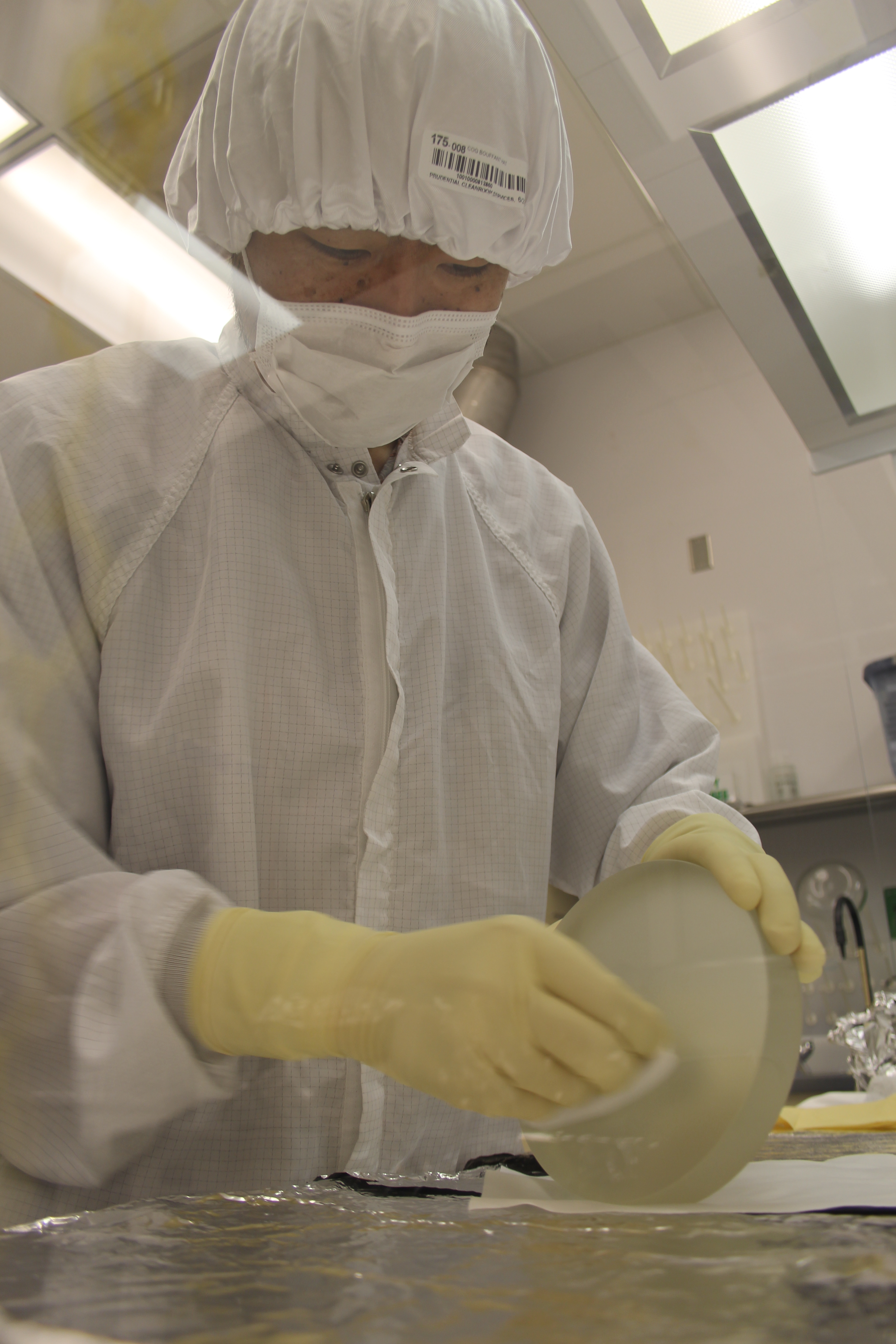
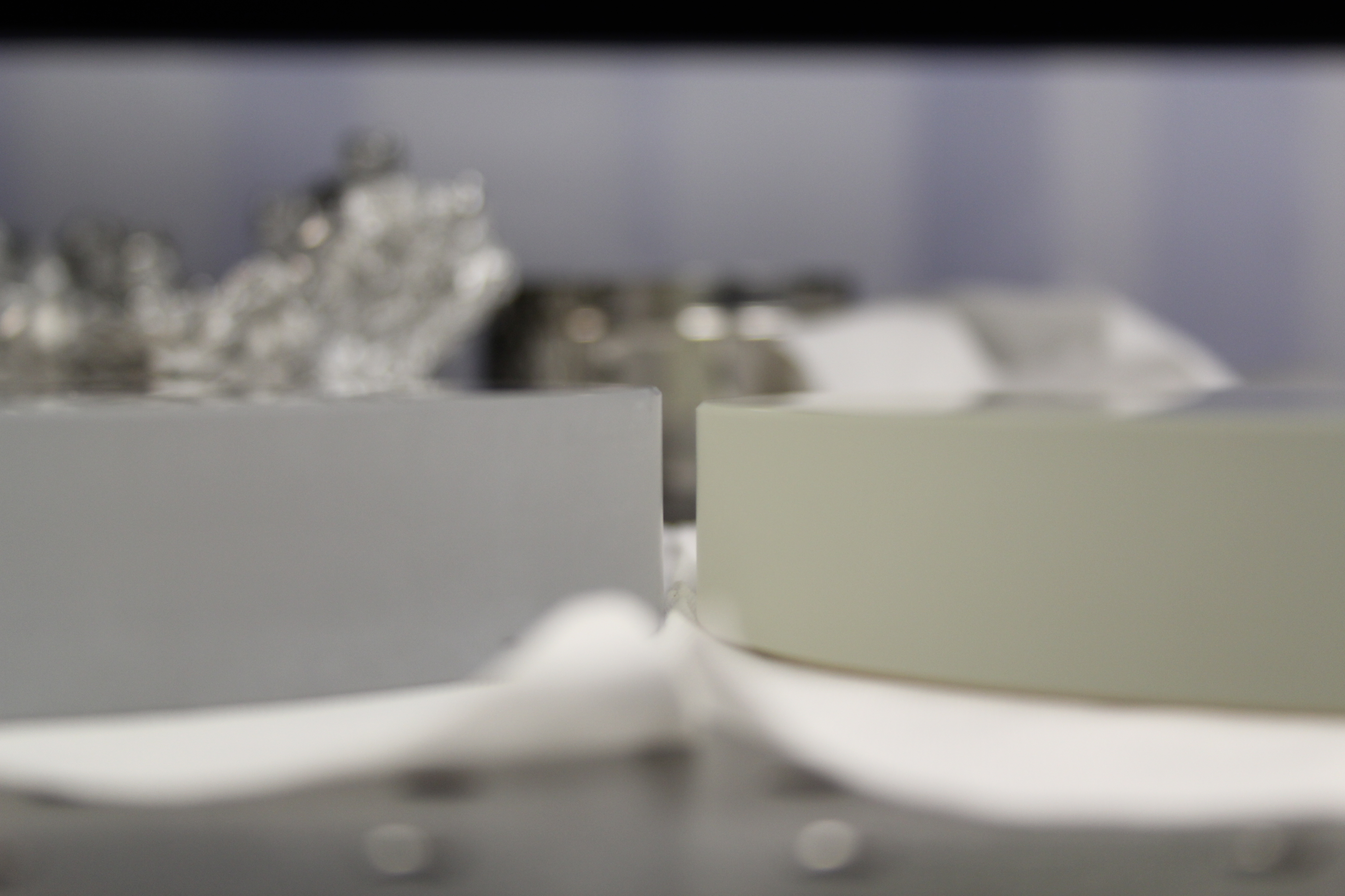
Both were cleaned and we took out to EX TMS Lab. We removed the Alignment mirror serving as an F1 Mirror and upon installing the new Newport mirror, Keita noticed that these mirrors are thinner (!). They are probably a couple millimeters thinner than the original mirrors. We were able to accomodate the mirrors by screwing the pitch/yaw actuators out a little more. New mirror was installed and this is where we stopped for the day.
Attached to this entry are a sample of photos.
"Orders of magnitude" is a serious comment.
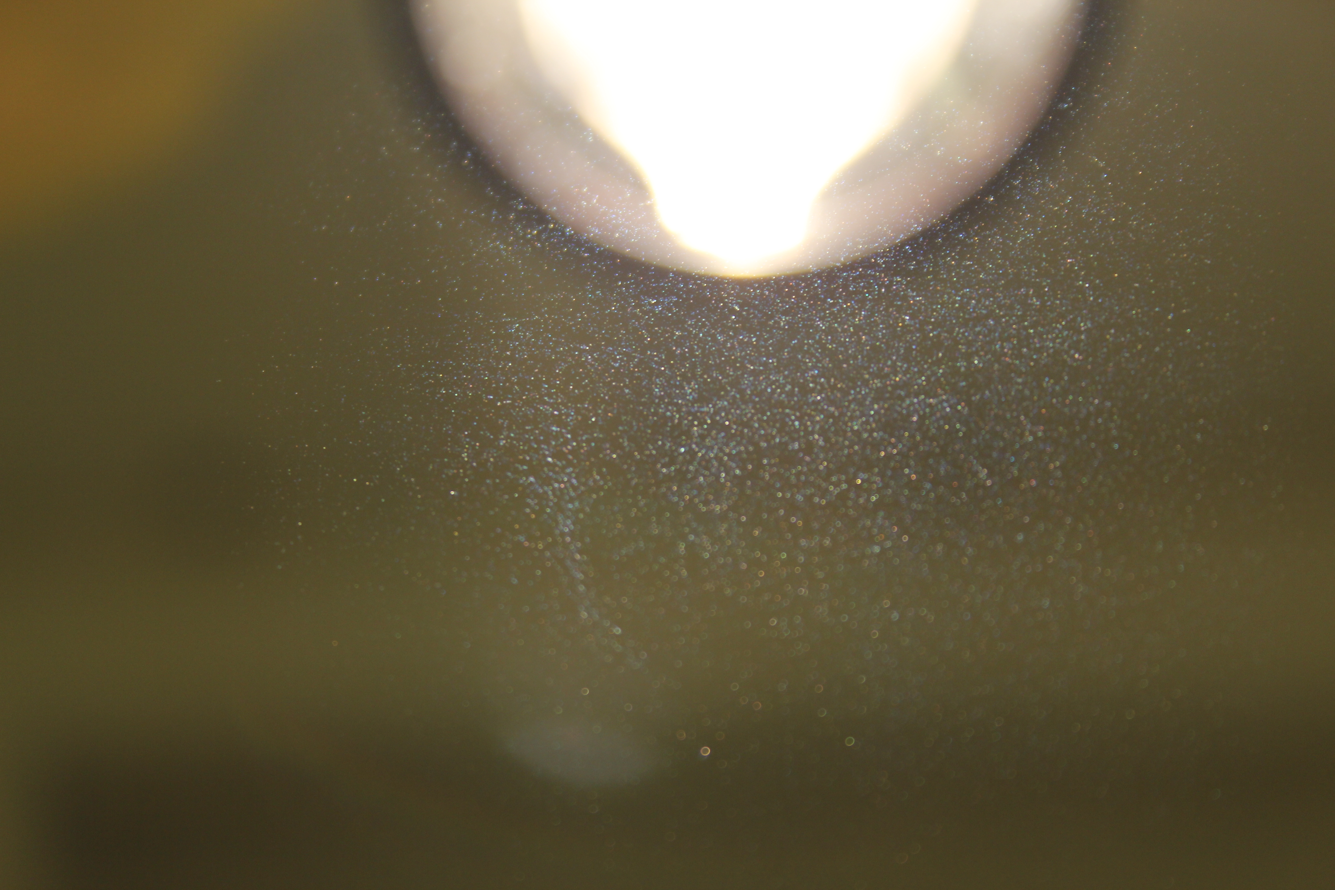
You can see many tiny spot defects on the new mirror because it's without other terrible things.
As far as the number of coating holes per area is concerned, the new one (Newport) is roughly three orders of magnitude better than the best Edmund mirror (picture) and the alignment mirror (picture).
No systemic scratch (VS something like this bad Edmund).
A very faint bluish color was found in the new mirror but it's much much better than Edmunds.
Mitchell Robinson, Scott Shankle, Thomas Vo - Arm Cavity Baffle Suspension Assembly is complete and ready to suspend. Baffle Box assembly is in process. ----------------------------------------------- Mitchell Robinson, Scott Shankle, Apollo's Randy and Scott - All participants reviewed the Installation Procedure and the Hazard Analysis. The Manifold Cryopump Baffle was brought down from the Balancing Fixture. The Flange Protectors and Baffle Alignment Tooling were attached to the spool. Yet, this baffle continues to be a complete pain in the derriere - the newly fabricated Spacer/Shim's holes are too small. Team will be looking into the feasibility of a clean modification. ----------------------------------
For the DetCharians: as of 1058670016 July 23 2013 20:00 PDT Jul 24 2013 03:00:00 UTC we are leaving the IFO in the following configuration: Input Mode Cleaner: LOCKED (offload to MC2 stages M2 and M2 only, under slow WFS control) Green Arm: LOCKED (no offload to HEPI) HAM2 & HAM3 HEPI: Floating, with offsets, but no control HAM2 & HAM3 ISI: Level 2 isolated All HSTS SUS: Level 1.5 "resg" damping filters filter PR3: Level 1.0 damping filters ITM HEPI: Locked ITM ISI: Level 2 isolated ITM QUAD: Level 2.1 damped BS HEPI: Level 2 isolated BS ISI: Level 2 isolated, but had to diable GS13 watchdogs while isolating to get it up and running BS Triple: Level 2.0 damping filters ETM HEPI: Level 2 isolated ETM ISI: Level 2 isolated ETM QUAD: Level 2.1 damped May it stay locked all night! The calibrated channel for green is H1:ALS-Y_REFL_CTRL_OUT_DQ, in [Hz] (so multiply by lambda*(L/c) to get [m]) The calibrated channels for the IMC are IMC_L = H1:IMC-X_DQ in [m] IMC_F = H1:IMC-F_OUT_DQ in [m]
Note, I missed Vincent's comment about turning on the ST0 to ST1 feed forward in his BSC-ISI and BSC-HPI instruction manual, so none of the BSC-ISIs had their ST0-ST1 FF on for this lock stretch. (This may explain the difficulty behind getting ISI-BS up and running).
[Jeff K., Kiwamu]
We took a look at the IMC locking after Hugo was done (alog 7189).
The tranmitted light still reaches 2300 counts at H1:IMC-MC2_TRANS_SUM_OUTPUT wihtout tweaking alignment which is good even though the WFS is not engaged.
HAM2 and HAM3 HEPI were released today.
Raw IPS readouts were recorded prior to release. The following offests were set in the actuation path to reestablish alignment, based on the IPS readouts:
OFFSETS (cnt) | ||
HAM2 | HAM3 | |
H1 | 370 | 900 |
H2 | 800 | 200 |
H3 | -600 | 350 |
H4 | -400 | -650 |
V1 | 450 | 300 |
V2 | 460 | -650 |
V3 | 1050 | 200 |
V4 | 900 | 1250 |
IPS readouts were recorded after reestablishing alignment:
NEW READOUTS (cnt) | ||
HAM2 | HAM3 | |
H1 | 1438.7 | 6664 |
H2 | 957.61 | -4089.2 |
H3 | 2089.2 | 9159.3 |
H4 | -1238.1 | -2252.5 |
V1 | -2796.8 | 2709.1 |
V2 | -608.92 | -6394.7 |
V3 | 1029.5 | 2257 |
V4 | -2862.8 | -9434.1 |
The Before/After difference in IPS readout is shown below:
BEFORE/AFTER DIFFERENCE (cnt) | ||
HAM2 | HAM3 | |
H1 | 107.6 | 146.6 |
H2 | 0.11 | 588.7 |
H3 | 68.2 | 169.1 |
H4 | 65.5 | 104.3 |
V1 | 54.1 | 155.1 |
V2 | 97.09 | 32.3 |
V3 | 4.5 | 144.5 |
V4 | 20.1 | 38.3 |
The remaining shift in alignment induced by unlocking HAM2 and HAM3 HEPI is less than 0.25mils (147 counts on the IPS), on each pier, after reestablishing the alignent with offsets on the actuation path.
Note: Isolation loops tripped only on HAM2-ISI. They are back ON now.
The DC part of those loops (CPS Biases) remain unchanged from prior to HEPI release, hence ensuring consistent alignment of the platforms.
Vented spool (in place of iLIGO BSC5) annuli -> No inner O-ring leakage -> removed temporary O-ring valves from bolted joint pump ports and connected permanent ion pump piping -> pumping annulus system with aux. cart overnight
For future reference, The calibrated channel representing the frequency of the green laser (in [Hz]) is H1:ALS-Y_REFL_CTRL_OUT_DQ This can be converted to the length of the arm cavity using the free spectral range, Cavity Length = lambda * (L / c) * H1:ALS-Y_REFL_CTRL_OUT_DQ
Careful: Since we implemented a bypass path from the PDH board to the laser, there is 22dB less signal on H1:ALSY_REFL_CTRL_OUT_DQ (the fast slider on the Sigg board is at -22dB, since this signal is now goint to the laser). This means that the calibration has to be corrected by these 22dB. See elog 6900.
GregG unlocked these suspensions and they are now floating again after a long hiatus of sequestration. Please regard the "Unlocked" signs and be mindful of any mechanical shorts against the floating elements. If you drop a screw or other smaller item, don't just forget about it as it may short the suspension too. Please avoid stepping on the Crossbeams if you don't wish to hear about it from BetsyW!
Bubba craning small loads over tube (consulted with Worden) Lots of CDS work for Maintenance… Paradise Water on site. Arnaud started running Transfer Functions on HAM2/HAM3 Work on HAM 2 - Hugh
today we restarted the DAQ about 16 times. I'll abbreviate this as DR.
First due to the restart of h1iscey the new h1pemey model was loaded. A DR was needed to resync the DAQ.
I created a new h1peml0 model as per Roberts latest changes. I restarted h1peml0 and did a DR.
Bad DUST channels in the DAQ. We found that some of the DUST EPICS channels went bad in the frame starting 7/9 when I added EX to the DAQ. To verify this I first took out all the ECAT channels from the EDCU (DR), and then I removed all the EX systems from the DAQ (DR).
The number of EDCU channels changed from 195,003 to 191,506 to 173,744. At the lowest number the DUST channels became good again.
To figure out what number of channels would break it again I put the ECAT channels back in (DR) and then h1susex (DR). The number of channels went to from 177,241 to 185,360 at which point some DUST channels went back to not as many. Later I put the system back to the full 195,007 (DR) and the full set of bad DUST channels came back.
For more info we moved DUST channels around in the H0EDCU_DUST.ini (DR) and found that the position within the file determined which ones were bad (for e.g. 3rd and 5th slots were bad). We moved the order of the H0EDCU_DUST.ini in the master file (DR)(did not change anything) and removed the H0EDCU_WEATHER.ini from the DAQ (DR)(did not change anything).
Hugo found ADC noise on the ISI HAM6 system. We power cycled the h1seih16 front end computer and the IO Chassis with no success. I removed the ADC cable and the noise went away. At this point I handed the problem over to Richard and Filiburto.
The latest Beckhoff ini files were ingested into the DAQ (DR)
A reminder that all our fast DAQ channels show up in RED due to the incorrect dataValid flag. This will be fixed next week when we upgrade to RCG2.7
J. Kissel, A. Pele For some reason the CART2EUL Matrices had been lost over some reboot / burt restore cycle. We've re-installed them, and captured + committed a new safe.snap. Install instructions: ]$ matlab -nosplash -nojvm >> cd /opt/rtcds/userapps/release/isc/common/projections/ >> load ISI2SUS_projection_file >> fill_matrix_values('H1:SUS-BS_M1_CART2EUL',ISI2SUSprojections.h1.bs.CART2EUL) >> fill_matrix_values('H1:SUS-BS_M1_EUL2CART',ISI2SUSprojections.h1.bs.EUL2CART) >> cd /ligo/svncommon/SusSVN/sus/trunk/Common/MatlabTools/ >> save_safe_snap('H1','BS') >> exit ]$ svn commit -m "New safe.snap file for H1:BS" /opt/rtcds/userapps/release/sus/h1/burtfiles/h1susbs_safe.snap
The demodulation phase of the IMC rotated by approximately 90 degrees. This is the third time to see this kind of phase rotation in the IMC. Very strange.
Temporary fix:
Temporarily I switched the signal from the I to Q signal by changing the actual cabling at the corner field rack and flipped the control sign at H1:IMC-REFL_SERVO_IN1POL by toggling the switch in the upper left of the IMC board screen. The IMC is now locking and should serve as an interferometric monitor for the sus and seismic people. The WFS loops are currently disabled by setting H1:IMC-WFS_GAIN to be zero to avoid a meaningless control. It seems the IMC started dropping its lock after Roberts and his company entered the PSL enclosure. The temperature transient somehow caused it ? It is unclear.
By the way the attached is a picture of the current I-mon and Q-mon signals in a X-Y projection. The I-mon is x-axis and Q-mon is y-axis. You can see a line almost in parallel to the y-axis indicating that the IMC length signal shows up mostly in the Q-phase.
To make it clearer, I flipped H1:IMC-REFL_SERVO_IN1POL to be minus (a.k.a. 1).
Prior to releasing HAM2 and HAM3 HEPIs, we recorded the readouts on the postion sensors of the ISIs, and HEPIs, of the input mode cleaner.
HAM2 ISI, raw CPS readouts, in counts
H1 -3388.2
H2 -2936.6
H3 -504.78
V1 -138.78
V2 -966.74
V3 -737.11
HAM3 ISI, raw CPS readouts, in counts
H1 -526.93
H2 266.35
H3 -175.73
V1 -1405.1
V2 -1102.9
V3 -560.2
HAM1 HEPI, raw IPS readouts, in counts
H1 8075.8
H2 -2940.6
H3 -8136.2
H4 -1306.2
V1 182.27
V2 4545.2
V3 -1657.4
V4 -1572.6
HAM2 HEPI, raw IPS readouts, in counts
H1 1331.1
H2 957.72
H3 2157.4
H4 -1303.6
V1 -2742.7
V2 -511.83
V3 1034
V4 -2882.9
HAM3 HEPI, raw IPS readouts, in counts
H1 6517.4
H2 -4677.9
H3 9328.4
H4 -2148.2
V1 2864.2
V2 -6362.4
V3 2112.5
V4 -9395.8
I made, and used, a script to retrevieve all this information at once:
/ligo/svncommon/SeiSVN/seismic/Common/MatlabTools/IMC_ISI_HEPI_position.m
It is commited under the SVN (r7458)
In preparation for unlocking HAM2 and HAM3 HEPIs, here are the alignments and static positions (as measured by the OSEMs) before unlocking, for reference. HAM2 (* indicates alignment offsets are OFF currently, because Arnaud is measuring some lower stage transfer functions) MC1 MC3 PR3 PRM P [urad] +312 +261 -148* -770* Y [urad] -968 -1081 124* -1200* M1T1 [ct] 12247 15407 11976 12430 M1T2 [ct] 13061 15166 16039 14890 M1T3 [ct] 13600 14370 15890 13874 M1LF [ct] 15975 15170 10659 11306 M1RT [ct] 9539 7682 10424 11068 M1SD [ct] 11831 11578 13022 12813 M2UL [ct] 16070 18355 7212 17435 M2LL [ct] 20649 14340 10466 2510 M2UR [ct] 7266 12539 10768 17270 M2LR [ct] 14008 9908 8883 2492 M3UL [ct] 14414 15096 7667 16049 M3LL [ct] 21812 15740 10337 3730 M3UR [ct] 10138 11881 10654 14385 M3LR [ct] 18289 7221 7899 4566 HAM3 MC2 PR2 P [urad] +434 +716* Y [urad] +244 +120* M1T1 [ct] 13708 14293 M1T2 [ct] 12670 12692 M1T3 [ct] 13585 12476 M1LF [ct] 12330 13635 M1RT [ct] 13636 14635 M1SD [ct] 14254 13127 M2UL [ct] 11830 14296 M2LL [ct] 9944 15369 M2UR [ct] 12493 12516 M2LR [ct] 13180 12042 M3UL [ct] 11333 12223 M3LL [ct] 9213 14342 M3UR [ct] 11356 8504 M3LR [ct] 8200 14608
The BS optical lever has been realigned with HEPI unlocked (and untripped), ISI damped and SUS damped. This is also with a verbal OK from ISC saying that the current alignment of the optic is good.
The dust monitors in the LVEA are NOT currently being recorded. It appears swapping the dust monitor in the H1 PSL enclosure has broken the communications.
Upon startup the IOC communicates correctly with each dust monitor until it gets to location 16 (the one that was swapped yesterday). After this it starts reporting back errors of the form: Error: ../commands.c: 49: Sent command � not echoed Received ?
I powercycled the Comtrol this morning. It worked after location 16 for a little while, but the error has returned.
Robert says he swapped the dust monitor in the H1 PSL laser enclosure. First one dust monitor was disconnected from the breakout box outside the entire H1 PSL enclosure. If I recall correctly, the dust monitor at location 16 was then still found by the IOC. The communication errors persisted. The first dust monitor was plugged back in and the other one disconnected. The IOC still found the dust monitor at location 16, but the communication errors went away. The dust monitor at location 16 reported calibration errors. It may be that the wrong dust monitor was swapped, leading to two set at the same location number, but this would not explain why the communication errors persisted after the first one was disconnected. As it stands, one of the dust monitors in the H1 PSL enclosure is disconnected. The dust monitor at location 16 is reporting calibration errors. I am not sure where the dust monitor at location 16 is. The dust monitor at location 10 is not found by the IOC. The remainder of the dust monitors in the LVEA are running again.
Sheila swapped the dust monitor in the anteroom with one programmed at location 10. The one she removed from the anteroom is labeled 'H'. It had no charge left in the battery when I got it. There was no change in the status. The dust monitor at location 10 is still unseen, and the dust monitor at location 16 is still giving calibration errors. This leads me to believe that: The dust monitor at location 16 is in the laser room and has calibration errors. The dust monitor at location 10 is in the anteroom and is unplugged at the breakout box outside the enclosure.