(Jax, Alexa, Stefan, Sheila, Daniel)
Arm locking achieved!
As of 18:00 local time, we're getting lock to 00 at a level of 10000 cts on H1: ALS-Y_REFL_B_LF_OUT, out of a maximum of about 22000 cts. This is about a 50% drop.
We've touched up the pitch and yaw to improve locking characteristics. The current positions in pitch/yaw are
ETM: (-142.7, 197.0)
ITM: (247.5, -271.5)
The current gain on CMB-B input 1 is -18 dB.
per WP 3937, GregG moved the HEPI Actuators on BSC2 to run mode. We've been bleeding this chamber for 3 weeks, better not be much air left. Tomorrow we'll think about releasing the locks and doing some commissioning.
We continue working away at the long list of items that need to be completed prior to PCal-CPB-ACB-ETMX install. Today, the ISI was moved from the Staging Building to X End VEA using a slow-moving Big Red. The CPB jigs were flown over the LVEA beamtube, loaded onto the trailer, transported to X End and placed in the VEA. See updated list below. 1. Watch CPB CR particle count trends (Patrick and Michael)-Things look acceptable: 0/0 this morning when I checked. 2. Get CPB Jigs and Walking Plates from LVEA to X End VEA (Apollo) 3. Remove PEM fence etc and tape holes (Apollo) 4. “Cheat” CPB CR as far towards wall as possible to provide space for CPB Assembly/Install (Apollo) 5. Cover concrete with CPStat to minimize particulate (Apollo) 6. Close up hole in CPB CR roof with CPStat or C-3 (Apollo) 7. Install and test leg jacks on BSC CR (Apollo) 8. Remove ISI Storage container top from building: move to X Mid-First Bay (Apollo) 9. Move E-module and Spiral Staircase into VEA (Apollo) 10. Remove door from BSC9 for PCal install (Apollo)-Put hard cover in place until door is needed by PCal? 11. Place lower Garbing/Staging CR (Apollo) 12. Assemble and place E-module including upper garbing/staging cleanroom (Apollo) 13. Place Test Stand (Apollo/IAS) 14. Clean Test Stand and cleanrooms: CPB, Test Stand, Work Space and lower G/S (Tech Cleaners) 15. Fly ISI to Test Stand (SEI/Apollo) 16. Move Test Stand CR over ISI (Apollo) 17. Get ISI Storage Pallet out of VEA (Apollo) 18. Place Work Space CR (Apollo) 19. Week of 10 June 2013 a. Welding Practice begins (SUS) b. Do PCal work at spool (Rick and crew-Apollo help) -Remove hard cover from spool -Install-Test-Turn parallel to beamtube -Close-out check 20. Marry SUS to ISI (SUS/Apollo) 21. Level, balance and test ISI (SEI) 22. SUS check-out (SUS) 23. Assemble Bosch frame for TMS (before 17 June 2013-nominal date for telescope alignment to begin)-Hardware at VPW 24. Clean CPB CR (Tech Cleaners) 25. Move CPB parts into VEA 26. Assemble CPB and cover (AOS Team) 08 July 2013 27. Install CPB (AOS Team) 28. Orient PCal properly (Rick and crew) 29. Remove dome (Apollo) 30. Insert ACB Assembly into beamtube thru open BSC door (AOS Team) 31. Lower BSC cleanroom (Apollo) 32. Install cartridge (SEI/Apollo) 33. Raise BSC cleanroom (Apollo) 34. Install walking plates (Apollo)
Cyrus, Jim The h1pemmx models died 12:22:42 UTC June 2. At Mid X, found that portable power supply supplying the +24V to the I/O chassis had died, along with a mouse that was laying next to it. Replaced the portable supply with a Sorenson from the EE Lab (given to us by Filiberto). Power cycled the timing system hoping to get rid of the 1/2 second time difference that appears on the MEDM screens. This did not have any visible effect on the timing, so we suspect we may have to wait until we get a known good pair of fibers for timing to the mid station identified before this is cleared up. Powered up the I/O chassis and front-end computer, the h1pemmx model is now running.
Patrick T., Sheila D. Since it was swapped in for troubleshooting, this chassis had been sitting on top of the corner station 2 chassis in the rack in the H1 electronics room. We added brackets to it and mounted it in the rack. There is now space below it for airflow for the corner station 2 chassis.
This work falls under permit 3936. For all the dust monitors (except for the one in the H1 PSL diode room (h1dustdr) which was started yesterday with the latest code version) I moved the driver support code from met_one_227b-1.0.0 to met_one_227b-1.0.1 and the IOC code from dust_met_one_227b-1.0.2 to dust_met_one_227b-1.0.4. There is no real change in the driver support code, just an update to the default EPICS base directory. The IOC code also updates the default EPICS base directory and the path to the driver support code (to version 1.0.1). It also adds the IOC boot directory and database substitution files for the dust monitor in the H1 PSL diode room. I restarted all of the dust monitors. I created an autoBurt.req file for h1dustdr and added the channels to the alarm handler configuration file. I had already added a medm screen to the sitemap earlier. Jim B. added the channels to the DAQ.
A new tool called WD_Plots was created by SEI at Stanford (Charles, Brian and I). It allows plotting the timeseries for a given set of sensors/actuators at the time of the latest WD trip, by simply using a button on an ISI's Watchdog MEDM screen.
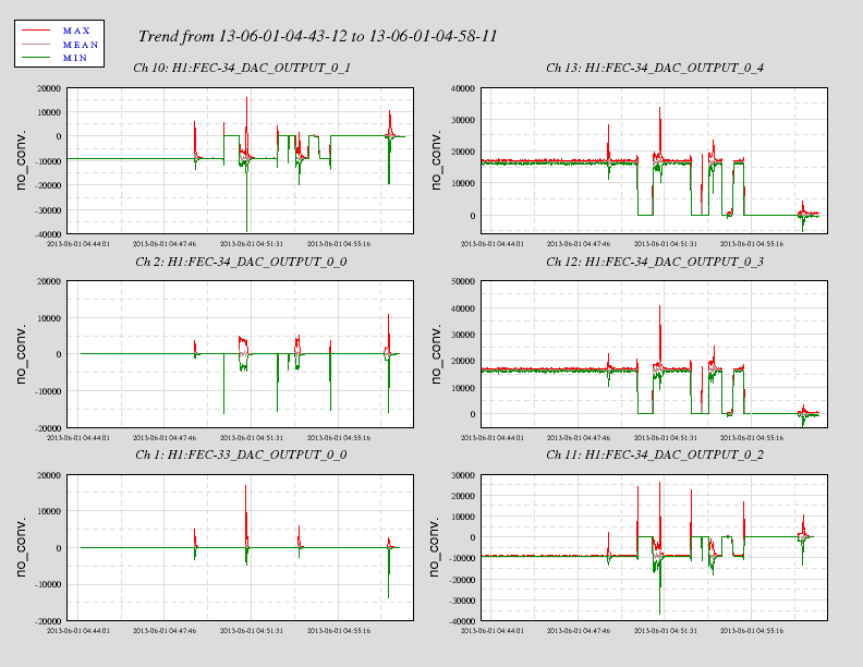
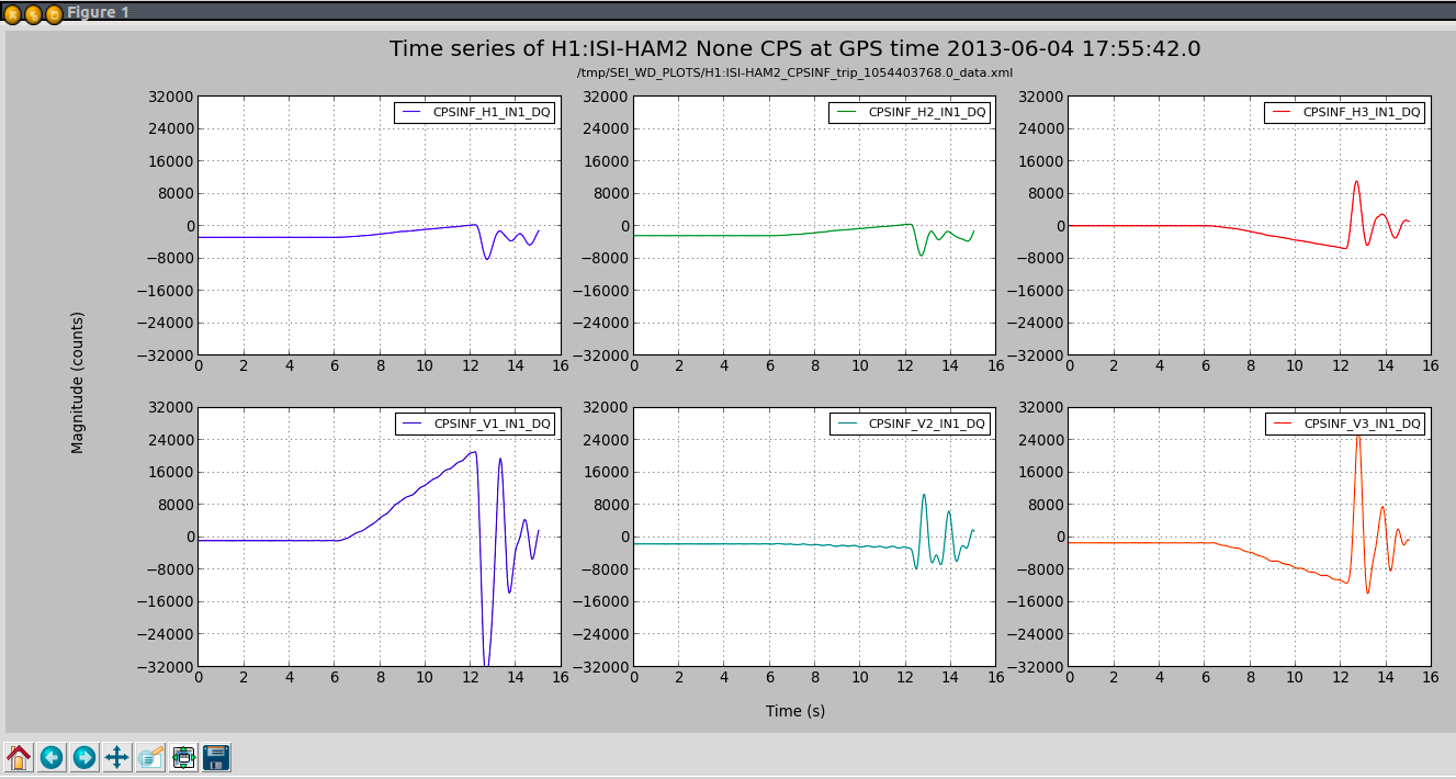
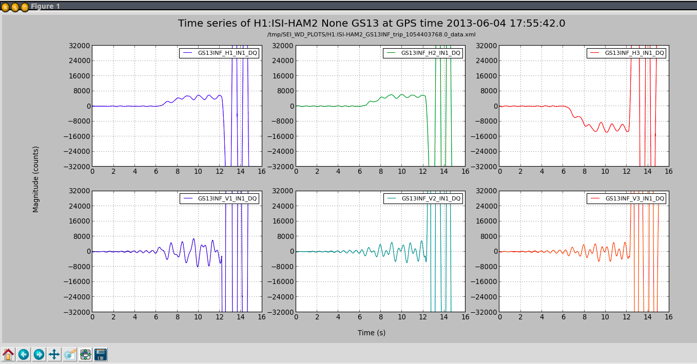
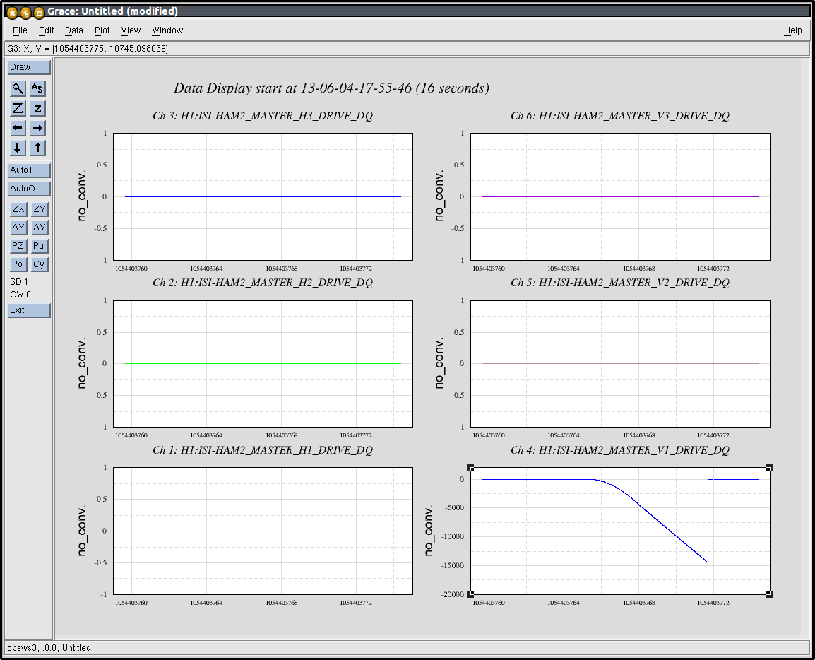
This tool was installed at LHO. Minor tweeks had to be made to stddir.py, which Jim Batch took care of. I tested it this morning (GPS time:1054403768) on HAM2-ISI.
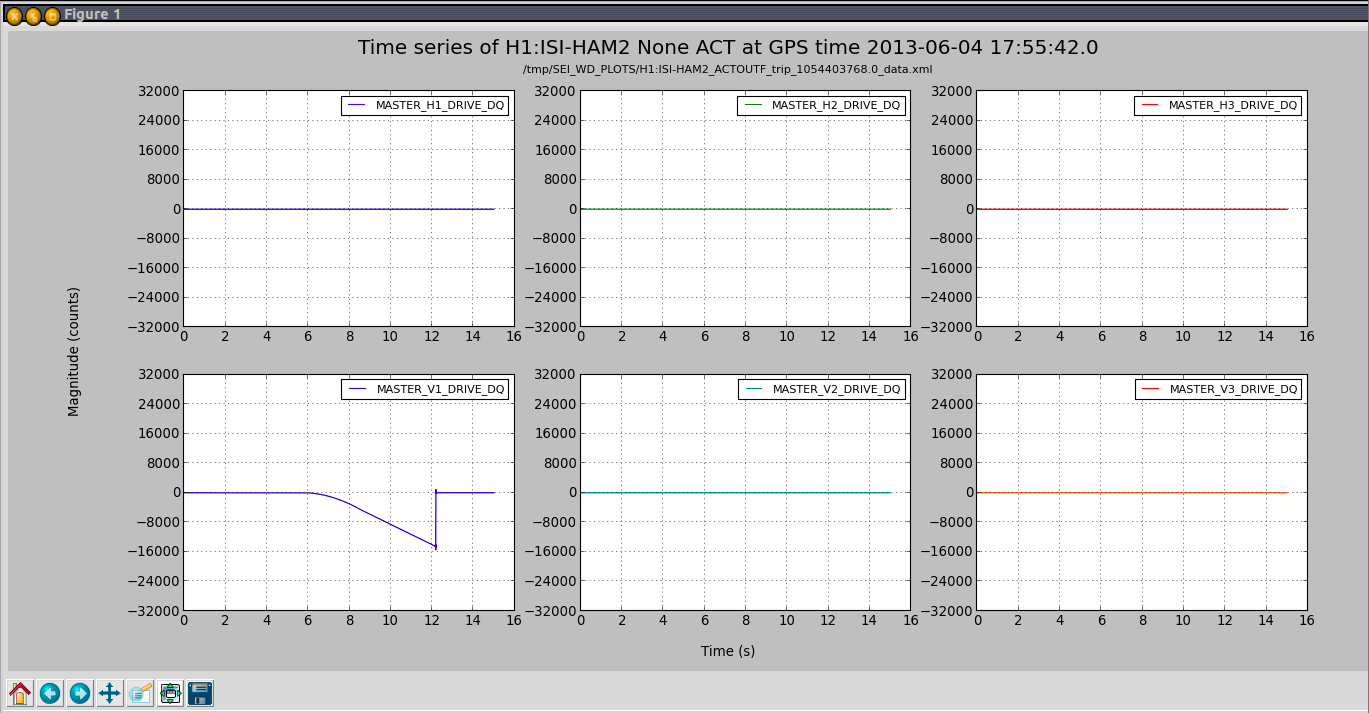
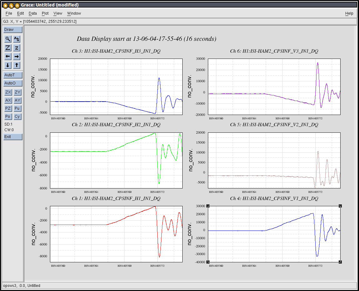
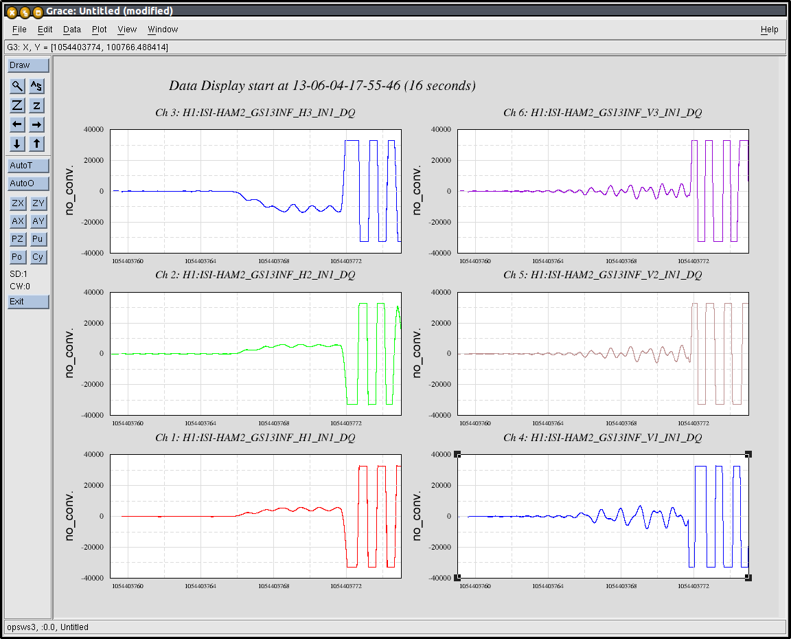
To do so, I tripped the ISI, on the CPSs with a 20,000cts ramp on V1. Produced plots are attached (ACT, CPS, GS13). They were compared to data retreived with Dataviewer (ACT, CPS, GS13). Channel routing appears to be correct. So is lookup time.
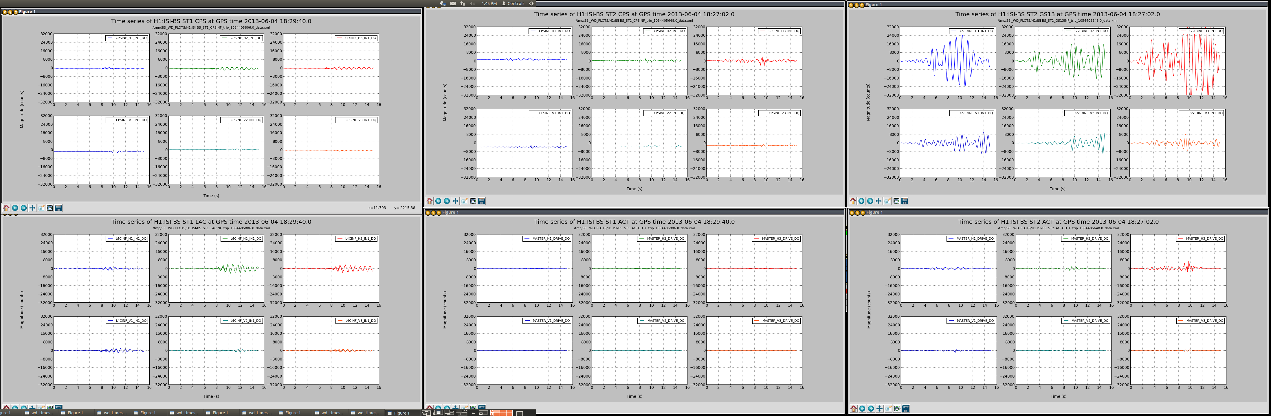
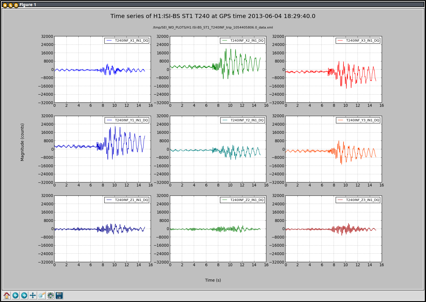
I also picked a tripped BSC (H1:ISI-BS) and tried producing the plots from its WD screens. Time series could be displayed for each sensor/actuator set (1, 2).
WD_Plots works at LHO. It may now be used by the operators to diagnose when an ISI trips.
I attached a pdf that shows how to use it from the ISI overview screens.
This is a first version that we are hoping to improve. Next, we plan on adding a vertical line to display the trip time on those plots.Further improvements could be done and operator feedback is welcome
Note:
The scripts used are commont to all ISIs. They are under revision control at:
opt/rtcds/userapps/release/isi/common/scripts/wd_plots/
The svn update performed on those scripts was covered by WP3903. Script were not changed since.
Attached are plots for the dust monitor placed in the cleaned 'dirty' clean room over the spool piece at end X. These are taken from 4 PM PDT May 31, 2013 to 7 AM PDT June 3, 2013. According to the logbook at the door, no one entered the VEA at end X over the weekend.
I have made a configuration change in the core switch to allow DHCP requests to be forwarded between subnets; this is to allow us to use a single pair of DHCP servers for all of the CDS subnets. Since we have been using (abusing?) the same configuration method to forward AWGTP discovery broadcasts to the Front End network, an ACL has been added to the OPS VLAN interface to filter out DHCP client requests from being forwarded to the FE network. Server replies are not filtered as these need to propagate to the networks that request them.
Added H1ECATC1_PLC2.ini, H1ECATY1_PLC1.ini, H1ECATY1_PLC2.ini, H1ECATY1_PLC3.ini to master file, removed H1EDCU_ECATC1.ini. Also edited H1EDCU_DUST.ini to include H1 diode room dust monitor channels. Restarted data concentrator, but data concentrator could not parse the H1ECATC1_PLC2.ini file. Error message "failed to locate first section in ...H1ECATC1_PLC2.ini" Edited the new H1ECAT* files, found "units=" missing actual units. Corrected, but the data concentrator still failed with the same error. Changed slope from 1 to 1.0, removed ^M from the end of the lines, no change, data concentrator still failed. Finally commented out the H1ECAT*.ini files to restart the data concentrator, as 20 minutes had passed. Examined the H1ECATC1_PLC2.ini file with "od -c", found 2 unprintable characters at the beginning of the file (octal 377, 376) at the beginning of the file, and each "normal" character has a trailing 000 (byte of value 0) after... 0000000 377 376 [ 000 d 000 e 000 f 000 a 000 u 000 l 000 Compare with a working .ini file: 0000000 [ d e f a u l t ] The script that generated the H1ECAT*.ini files needs some repair.
Guess the frame builder doesn't take Unicode...
The H1ECAT files are in a UTF-16 format. To convert to an ASCII format that the data concentrator can read, use the command iconv on a Linux workstation, as in the following: iconv -f UTF-16 -t UTF-8 H1ECATC1_PLC2.ini > tmp.txt mv tmp.txt H1ECATC1_PLC2.ini
A contamination control test is under way at the main LVEA man-door entrance. You will notice that three frames of sticky mats have been removed and have been replaced by two large Dycem mats. The grey mat is for gross particulate removal and the blue mat is for fine particulate removal. The mats will be cleaned once per day.Picture below
I have access the H1 system to examine DAC outputs during the problem with the large M1 offsets (see aLOG entry). Note that DCUID 33 is the IOP model. DCUID 34 is the MC1 model. On MC1, DAC 0 0-5 are used. In the attached plot, you will see that there is indeed activity on the DAC outputs for DCUID=34 (MC1) at the same time the DCUID=33 (IOP) reports it, at least to this observer.
Eyeballing the offset amplitude in the channels shown in LHO aLOG 6599, the calibrations are: H1:SUS-MC1_M1_OSEMINF_T1_INMON (Open Light Compensation) (ADC) (SatAmp Transimpedance) (unit conversions) (Ideal OSEM Sensitivity) 9000 [ct] * 1.156 [ideal ct/individ ct] * (40/2^16) [V/ct] * (1/240e3) [A/V] * 1e6 [uA/A] * 1e-3 [mm/m] * (0.7/76.29) [ideal m/uA] = 0.00024277 [m] = 243 [um] H1:SUS-MC1_M1_VOLTMON_T1_MON (ADC) (Monitor Board Gain) (TOP Driver Output Admittance) (10D x 5T [mm] Magnet) 11000 [ct] * 40/2^16 [V/ct] * (3/2) [diff V/ s.e. V] * 0.0097693 [A/diff. V] * 0.963 [N/A] = 0.094744 [N] V = 0.094744 [N] * 0.002788 [m/N] (@ DC) = 0.00026415 [m] = 264 [um] R = 0.094744 [N] * 0.059918 [m] * 0.046156 [rad / N.m] (@ DC) = 0.00026202 [rad] = 262 [urad] (Encouragingly, the calibrated OSEMINF and VOLTMON amplitudes agree.) Note: in addition to the links already cited above, I've used a combination of the HAM Triple SUS Controls Design Description, and the information from the output of functions make_OSEM_filter_model(0.001,'HSTS','M1'), and generate_Triple_Model_production(0.001,'hstsopt_metal','/ligo/svncommon/SusSVN/sus/trunk/',false,true)
I am in the process of measuring the sensing matrix for the IMC WFS.
An issue I have been facing is that both WFS-A and B seem quite insensitive to the angular motion of MC1 and MC3.
(measurement of sensing matrix)
To measure the sensing matrix the way I have been doing is that :
I always get a signal with a high SNR when MC2 is excited. This is good. However the signal is always quite small when MC1 and/or MC3 are excited. In fact WFS-A and B are unable to detect the excited motions. I am not sure why at the moment. My feeling is that they behave as if the actuators on MC1 and MC3 are super weak.
In L1 we used the 'Witness' channels (such as L1:SUS-MC1_M3_WIT_PMON) to look at the actual motion excited in M3 while the drive was applied to M1.
Very good isolation results were presented in aLOG Sensor Correction Results. During the test, the ISI was the only controlled system. The ISI is locked at DC to stage 0 but the HEPI structure (stage 0) can still wander around since HEPI is not controlled.
HEPI position control:
Since isolation performances of the HEPI are limited (amplification of the motion around the blend frequency and the HEPI sensor correction is not as good as the ISI one), it seems attractive to implement a simple position control to lock HEPI to the ground and steer the whole HEPI-ISI as desired.
In this case, the HEPI-L4C inputs of the super sensors are turned off (via zero gain filters for convenience) and no filters applied to the IPSs.
Then, some rudimentary isolation loops (couple of poles and zeros) were designed such that the UGF is 100mHz. This low UGF allows not changing the HEPI dynamics in the ISI control bandwidth (Low gain peaking between 100mHz and 30Hz).
At low frequency, when no control is engaged, the ground, the HEPI and the ISI are moving together. With the sensor correction, the CPS signals are added to STS-2 signal to evaluate the inertial motion of stage 1. But when the stage 1 of the ISI is driven, HEPI-stage 0 also moves (cf aLOG Feedforward and figure transfer functions from ISI to HEPI in attachment – H1_ISI_ETMY_Interraction_HEPI_ISI_20130530.jpg). Consequently, the stage 1 inertial motion is misevaluated since HEPI motion is not considered.
By increasing the UGF of the position control on HEPI, the HEPI piers and stage 0 are locked together and the stage 1 inertial motion evaluation should be better.
In attachment H1_ISI_ETMY_ASD_Stage_1_Z_Different_Configuration_20130522.jpg , spectra of stage 1 motion in the Z direction are presented in different configurations:
- ISI controlled + No HEPI control
- ISI controlled (with sensor correction on stage 2) + HEPI control (UGF 10Hz - super sensor IPS +L4C + Sensor correction)
- ISI controlled (with sensor correction on stage 1&2) + HEPI control (Position control – UGF 100mHz)
- ISI controlled (with sensor correction on stage 1&2) + HEPI control (Position control – UGF 5Hz)
It seems that controlling the HEPI using a “pure position control” doesn’t improve or deteriorate the isolation performance of the ISI (vs no HEPI control) but it’s simpler to implement than the regular L4C-IPS blend.
Isolation is better when the sensor correction is implemented via the stage 1 of the ISI. Increasing the UGF of the position control from 100mHz to 5Hz doesn’t seem to improve the isolation of the ISI.
After reviewing the results, I found a calibration issue in the HEPI L4C in the X and Y directions. The couplings are actually lower than initialy presented. It explains why controlling the HEPI in position with a 5Hz UGF vs 100mHz doesn't seem to affect the sensor correction (Ground to stage 1 of the BSC-ISI).
As requested by Daniel, the TMS pointing is (-14400,9170). This hasn't changed from initial alignment conditions (yet).
Here are the positions of the BSC-ISI. CPS offsets are presented in nm.
HEPI-BSC1: Locked https://alog.ligo-wa.caltech.edu/aLOG/index.php?callRep=6566
HEPI-BSC6 is control in position
ISI-BSC6: Blend at 250mHz with T240 and level 3 controller
ISI-BSC1: Blend at 250mHz with T240 and level 1 controller