andres.ramirez@LIGO.ORG - posted 12:57, Friday 31 January 2014 (9720)
Going to BSC2 to work on HEPI (LVEA) - Hugh
Work completed
Work completed
We fixed Daniel's channel naming problem with the ALS addition to the ASC, actually the problem went away. So I restarted the new h1asc model at 12:41 and restarted the DAQ at 12:44 to install the new model and DAQ channels associated with it.
Noticed some fluid in the bottom of the SW SEI Pier at the BS. Cleaned up the mess in the Pier yesterday and this morning found fresh fluid. Climbed up to Housing and found the Vertical Actuator Fluid Catch overflowing. I can see drips coming off the Parker Valve. Can't tell if it is coming out of the Valve itself or just the Valve/Manifold seal. It looks like it could be the former. I'd like to clean up the catch and tighten the valve to manifold screws and see what it looks like in a couple days.
This may require a valve change which would briefly glitch the fluid pressures twice and in between have the BS HEPI uncontrolled for a few hours as we bleed after the valve change.
"Noisy" scroll pump located outside of building near LN2 dewar
Going to HAM 4 to prepare SR2 Pre-installation Plate (Cookie cutter) and hardware– Jeff B.
Starting Stiffener rings and o ring protectors installation on HAM4 - Apollo
Work completed!
(Alexa, Daniel, Keita)
After changing the RF frequency to 24.389319 MHz and adjusting the delay line phase to 257 steps, we took open loop transfer functions of the PDH loop.
PLL Board Settings:
PDH Board Settings (Nominal):
EX_PDH_OpenLoopTF_phase/mag_Nom.txt corresponds to the data collected with the above nominal settings.
EX_PDH_OpenLoopTF_phase/mah_Boost2On.txt corresponds to the data collected wiith the above settings with the addition of Boost 2 ON
EX_PDH_OpenLoopTF_phase/mag_6dBFast.txt corresponds to the data collected with the same as the nominal settings with the addition of 6dB gain in the fast path
Heading into the LVEA to check a dust monitor (location #9) which has lost communication - Patrick
Work completed!
Moving, cleaning, and organizing elements for SR2 installation (HAM4 LVEA) - Jeff.B/Jodi
PSL Check:
Laser Status:
SysStat is good
Output power is 29.3 W (should be around 30 W)
FRONTEND WATCH is Active

PMC:
It has been locked 2 day, 16 hr 11 minutes (should be days/weeks)
Reflected power is 1.1 Watts  and PowerSum = 12.16 Watts.
(Reflected Power should be <= 10% of PowerSum)

FSS:
It has been locked for 11 h and 22 min (should be days/weeks)
Threshold on transmitted photo-detector PD = 0.94V (should be 0.9V)

ISS:
The diffracted power is around 5.4% (should be 5-15%)
Last saturation event was 11 h and 28 minutes ago (should be days/weeks)
Disconnected temporary cabling that were used for testing of SR2 next to HAM4. Connected permanent cables to satellite units in SUS H1-R3. Permanent cabling were already pulled and connected at chamber side:

Cables were connected at chamber side according to D1101814.
D6-1C1: Cable SUS_HAM4-32 SR2 BOTTOM
D6-1C2: Cable SUS_HAM4-31 SR2 MIDDLE
D6-2C1: Cable SUS_HAM4-10 SR2 TOP
D6-2C2: Cable SUS_HAM4-11 SR2 RIGHT/LEFT

Filiberto Clara
Work completed!
Aidan, Thomas, Eric G.
We installed the TCS HWS HAM4 optics this afternoon per D1201098. We've finished using that area and the chamber is covered again.
Full details tomorrow.
Here are the full details ...
We had to place ten optics/opto-mechanics assemblies. The D1201098 installation kit (cookie cuters) parts were placed to facilitate placement and alignment of optic assemblies. The assemblies were then bolted into position, summarized below:
Photos are attached below. Complete set is on ResourceSpace
We plan on installing the 4x 2" lens mounts and optics during the alignment of these optics or earlier.

I have been silently checking the signal chain of the REFLAIR and POPAIR RFPDs using the AM laser (a.k.a. PD calibrator) to make sure that they are functional expectedly.
Summary
The RF frequency of the AM modulation was adjusted in each measurement such that the demodulated IF signal was below 50 Hz.
Calibration of the amplitude modulation depth
We recalibrated the AM laser.
The current setting of the laser was changed recently because we opened up the current driver when we thought the laser diode had been dead in the early December. Then the laser head and its current driver were sent to Rich at Caltech for his extensive testing although the laser magically fixed itself and he didn't find anything wrong. So this was the first time for us to use the AM laser which had been fixed. Because of that mysterious event, I wanted to recalibrate the laser. First of all, Yuta and I measured the power to be 2 mW with an Ophir Vega without the attenuation filter. Then we measured the modulation depth for the amplitude modulation by using a Newfocus 1611 as a reference.
The new calibration for the amplitude modulation is:
P_am = 5.13 mW x (P_dc / 1 mW) * (1 V / V_drive)
where P_dc is the laser power at DC and V_drive is the drive voltage when it is driven by a 50 Ohm source. For example, if one puts this laser to a PD which then shows a DC laser power of say 2 mW, the AM coefficient is now 5.13 mW x ( 2 mW / 1 mW) /V_drive = 10.26 mW/V_drive.
REFLAIR_A_RF9 (S1203919)
Remarks:
The signal chain is OK. The PD response is smaller by 15% for some reason.
It seems as if the transimpedance is smaller by 15% than what had been measured at Caltech (LIGO-S1203919). The cable loss from the RFPD to the rack was measured to be 0.47 dB. Be aware that the demod gain is half of the quad I/Q demodulator because this is a dual channel demod (see E1100044). The demod conversion gain is assumed to be 10.9 according to LIGO-F1100004-v4.
REFLAIR_A_RF45 (S1203919)
Remarks:
The signal chain is healthy.
Found cable loss of about 1.5 dB. The measurements excellently agree with the loss-included expectation.
POPAIR_A_RF9 (S1300521)
Remarks:
The signal chain is healthy.
The measurement suggests that there is loss of 1 dB somewhere. I didn't measure the cable loss this time.
POPAIR_A_RF45 (S1300521)
Remarks:
The signal chain is OK. Though loss sounds a bit too high.
The measurement suggests a possible loss of 2.6 dB somewhere. I didn't measure the cable loss.
REFLAIR_B_RF27 (S1200234)
Remarks:
The signal gain is bigger than the expectation by a factor of 2.3.
REFLAIR_B_RF135 (S1200234)
Remarks:
The signal gain is bigger than the expectation by a factor of 1.5
POPAIR_B_RF18 (S1200236)
Remarks:
The signal gain is bigger than the expectation by a factor of 2.3
POPAIR_B_RF90 (S1200236)
Remarks:
The signal gain matches with the expected value, but I don't believe this.
There was a typo:
P_am = 5.13 mW x (P_dc / 1 mW) * (1 V / V_drive)
P_am = 5.13 mW x (P_dc / 1 mW) x (V_drive / 1 V)
For 27MHz and 136.5MHz, the RF gains are +19.8dB and +50.7dB, respectively. S1400079
The response of the BBPD isn't really flat over all frequencies. See D1002969.
The description in D1002969 is for the initial version. (The schematics seems up-to-date.)
The latest version has the rf performance as attached.
This is a follow up of the calibration measurements for REFLAIR_B and POPAIR_B.
I have updated the expected signal gain for these photo detector chains using more realistic gains which Koji gave (see his comments above). Now all the values make sense. Note I did not perform any new measurements.
In the following calculations, the quantity in red represent the updated parameters.
REFLAIR_B_RF27(S1200234)
Remarks:
The signal chain is healthy. There is loss of 0.92 dB somewhere.
REFLAIR_B_RF135(S1200234)
Remarks:
The signal chain is OK. There is loss of 3.9 dB somewhere.
POPAIR_B_RF18 (S1200236)
Remarks:
The signal chain is healthy. The signal was bigger by 9% than the expected.
POPAIR_B_RF90 (S1200236)
Remarks:
The signal chain is healthy. There is loss of 1.2 dB somewhere.
From these measurements, we can use POPAIR to infer the calibration for POP.
I looked at a recent lock acquisition while the interferometer was trying to engage the outer ISS loop. The LSC is relatively stable during this time, and the POP beam diverter is still open.
After undoing whitening gain and digital gain (2 ct/ct for POPAIR9/45, and 32 ct/ct for POP9/45), we find the following TFs:
This implies calibrations of 1.7×10⁶ ct/W for POP9 and 1.8×10⁶ ct/W for POP45.
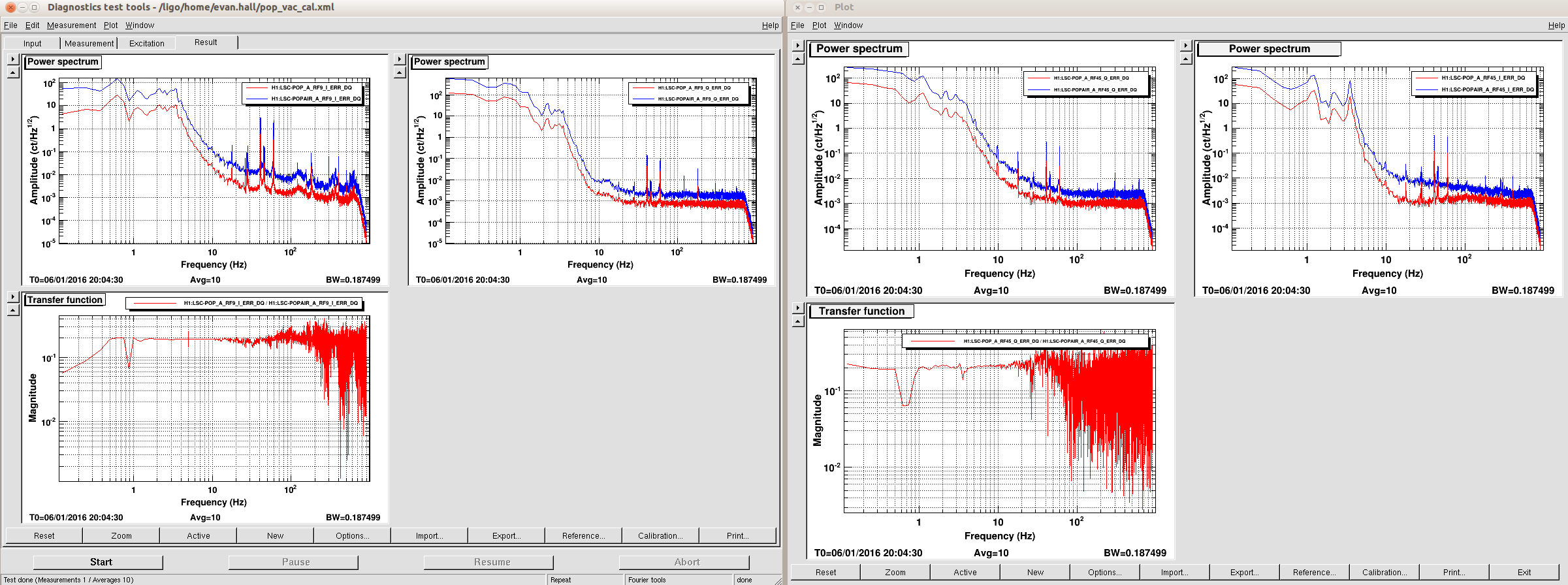
There's a factor of 4 difference in power between POP and POPAIR (17 mW versus 68 mW with a PSL power of 23 W), so the values I gave above are off by a factor of 4. The demod gains should be 6.4×10⁶ ct/W for POP9 and 7.2×10⁶ ct/W for POP45.
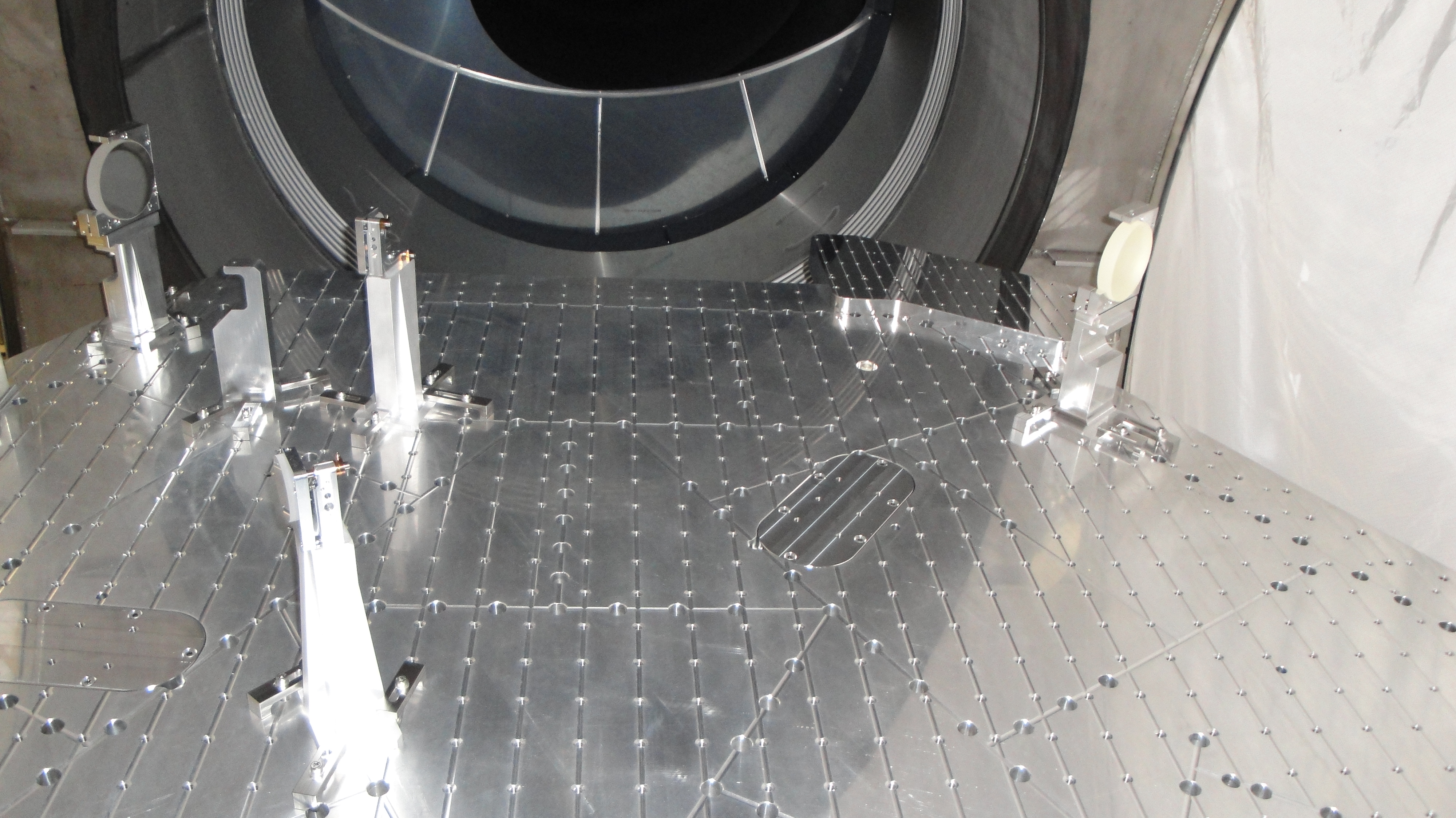
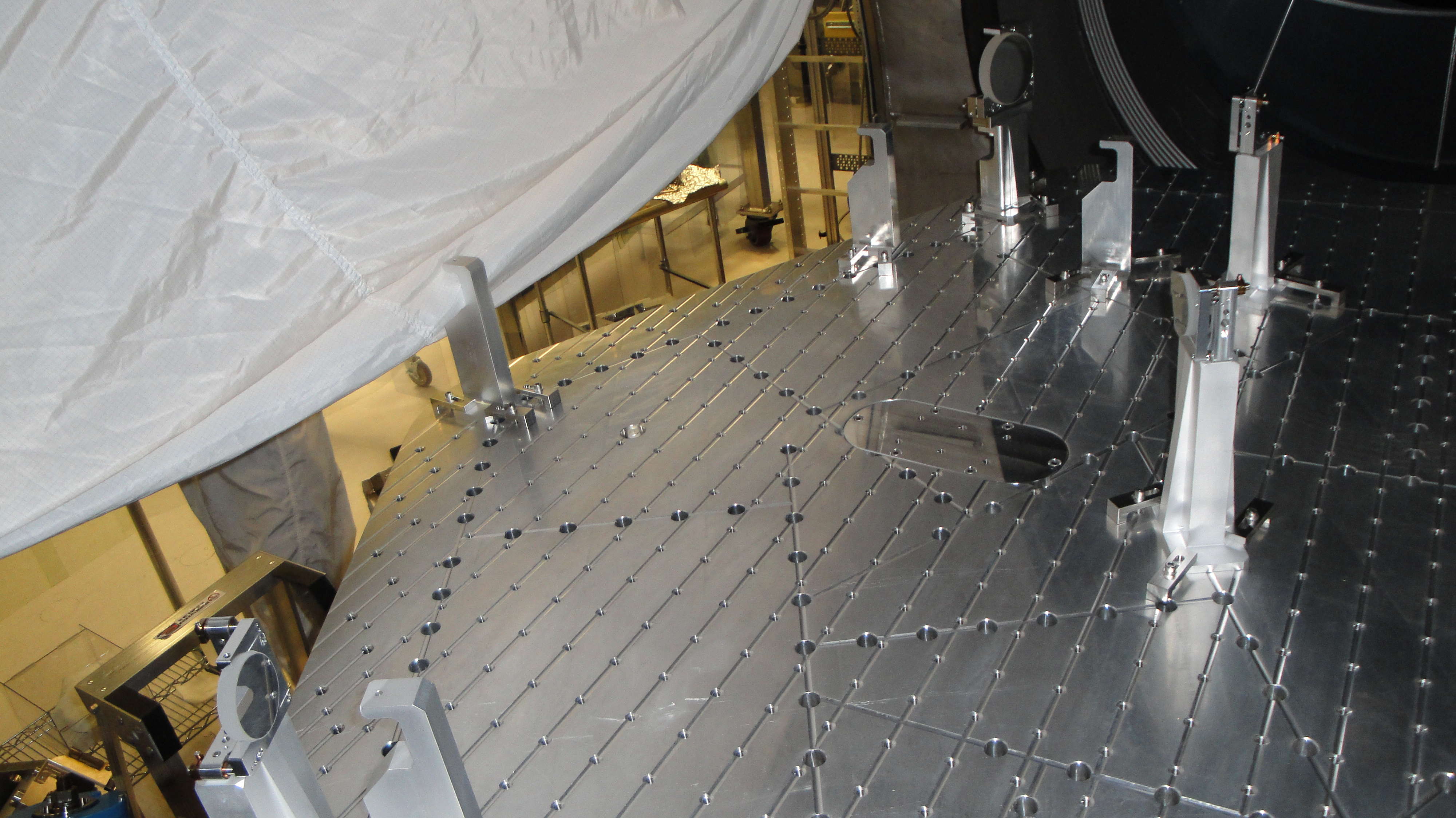
In preparation for acceptance review of the ETMX quadruple suspension, I took a set of ASD of the osems in the local and euler basis. ETMX is in chamber, under vacuum and the ISI was in its level 1 isolated state (ST1 = T100mHz blend on X and Y, T750mHz for the other DOF, ST2 = 750mHz blend). Measurement was taken successively with suspension damping on and off.
The main resonnances of main and reaction chains are well damped for all degrees of freedom.
The minor things to notice are :
Damping for the vertical DOF of the reaction chain is not having much effect on the first resonnance (@~ 0.56Hz) (see p9 of 2nd pdf).
The upper left osem of L2 level has its noise floor above the usual sensor noise we see on other osems (see p34 of 3rd pdf).
Otherwise everything else looks good.
The results attached are :
1) Comparison damping off/on for the top mass sensors of the main chain
2) Same for the reaction chain
3) Comparison between different quads (H1 ETMX H1 ETMY L1 ITMY L1 ITMX) of all osem sensors in local and euler basis.
A safe snapshot will need to be taken when possible since I found the normV/R/P filters disengaged, and a gain of 10 in the L2L L1 sensalign matrix. I also corrected the channel list of the plotquadspectra.m since it was requesting two times the L1_WIT_L channels. The modified script was commited to the svn
EULER DOF H1:SUS−ETMX_L1_WIT_L_DQ (pg 29 of third attachment) also shows excess noise, which is due to the factor of 10 in the sensalign matrix (was corrected this week and snapshot was saved)


I cleaned up the Catch Pan and checked the Valve to Manifold screws. They were plenty tight. When I look again (Monday, tomorrow?) I'll be pretty confident about from whence the leak comes but I fairly sure now that is is from the Valve itself.