kyle.ryan@LIGO.ORG - posted 16:12, Tuesday 17 September 2013 (7785)
CP6 alarms likely tonight due to overfill earlier today-no action required
Days Notes
Visitors
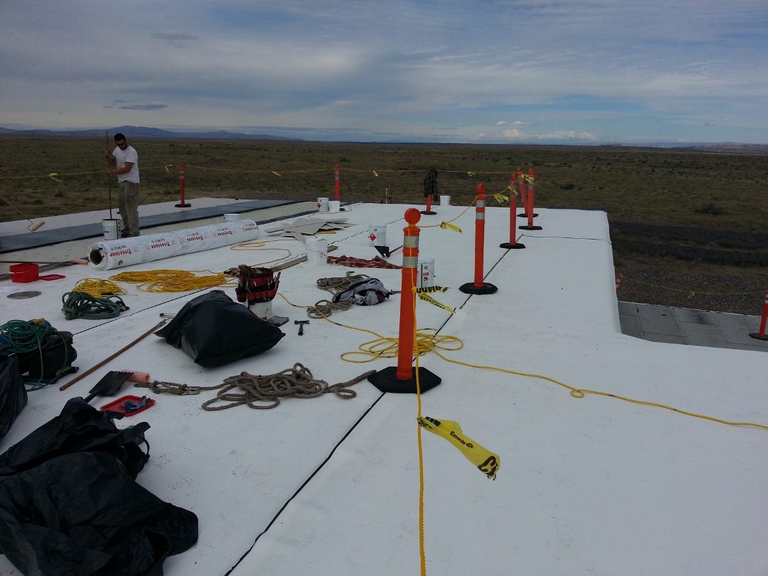
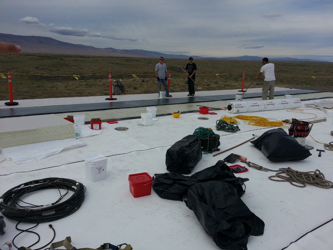
The new roof membrane is being glued in place at ENDX. A second crew was brought in today (due to rain at another job site) and has started at the Mid station stripping the flashing.
After getting the code back up and running I replaced the dust monitor that quit communicating with the corner station with  one provided by Patrick.  The New one is working just fine.

This took far longer than planned.  I was working on it yesterday only to find out that the code had been stopped so all the work yesterday was repeated this morning.  Then realized no one had tried the basic swap of monitors so this was the logical step for testing.  Once replaced I booted the comtroler again and Patrick restarted the code.  Everything appears to be working now.
Satellite S1100057 was replaced with S1100178 (MO_Left, MO_Right, RO_Left, RO_Right). This was done to help Jeff Kissel search for a 5.1HZ excitation signal he reported:
https://alog.ligo-wa.caltech.edu/aLOG/index.php?callRep=7737
The optical timing distribution system in the staging building is no longer in sync with the master timing in the MSR.  Because of this, the GPS time of the models running on the test stands is off by a second or two.  This should be fixed at some point when it is convenient to shut down the models and troubleshoot the system.  Until then, the system should work so this repair is not urgent.

This affects both seismic and suspension test stands in the staging building.
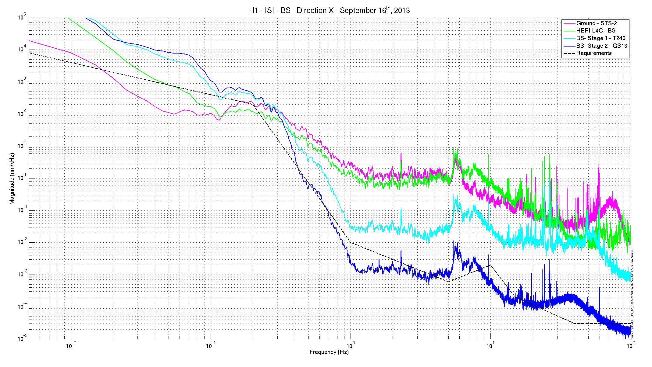
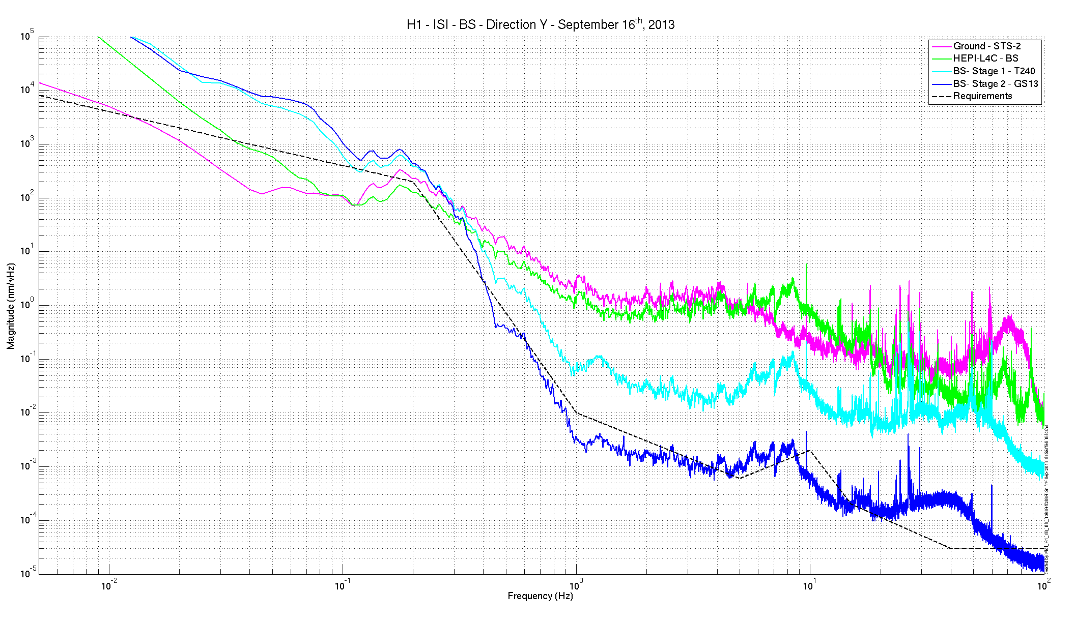
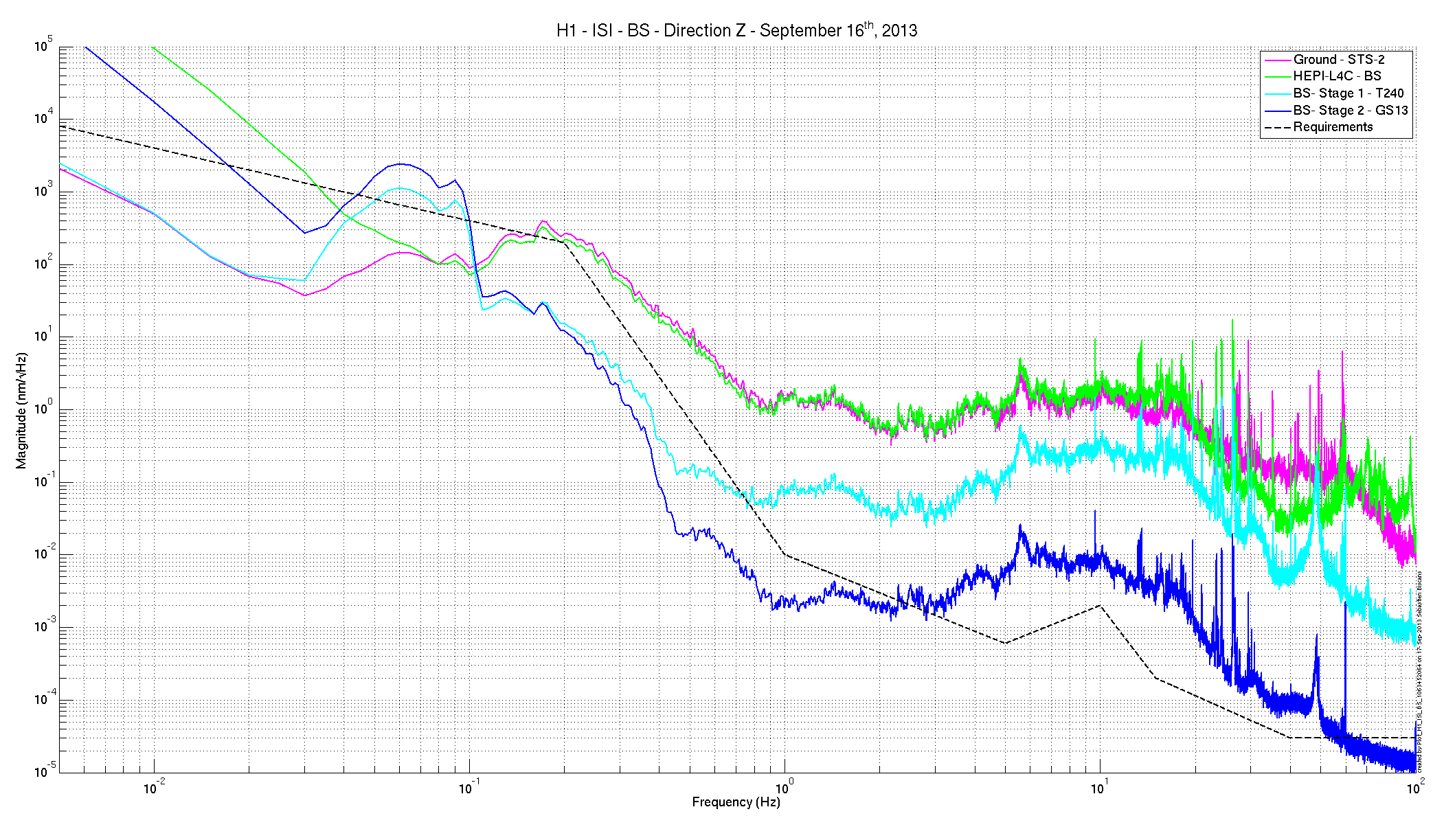
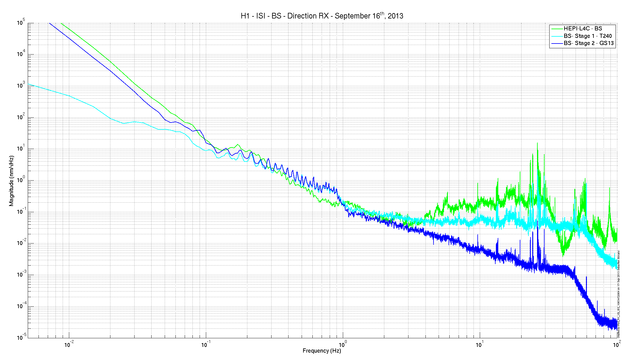
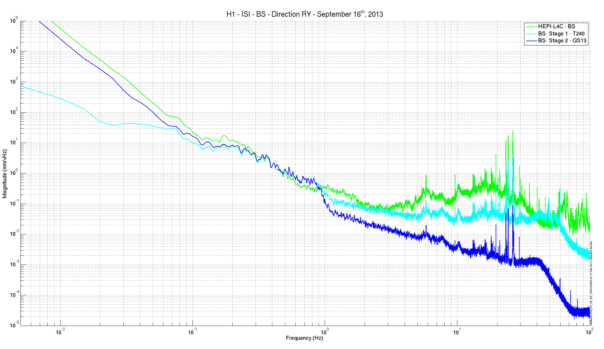
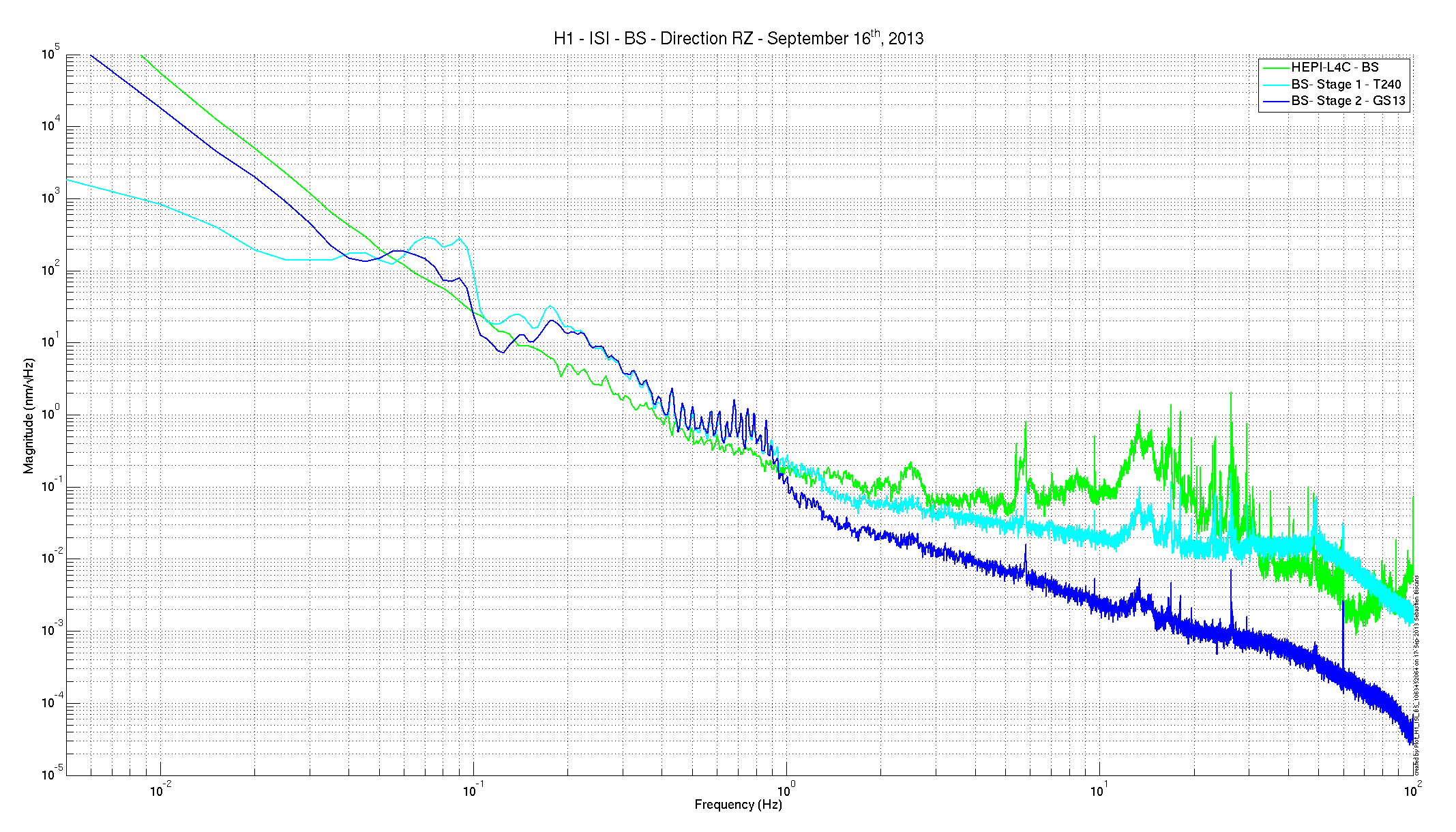
Find attached some performance plots for BSC-ISI BS. Those first results are promising, even if there is room for improvement and tweaking.
*** HEPI ***
- HEPI with position control (100mHz UGF)
- No feedforward
*** ISI ***
- Stage 1 blend
o 750mHz for RX, RY, RZ
o 100mHz for X, Y and Z
- Stage 2 blend
o 750mHz for RX, RY, RZ|
o 100mHz for X, Y and Z
- Level 3 controllers
o Stage 1 40-42Hz
o Stage 2 30-32Hz
- Feedforward ON
- Sensor correction from the ground ON
*** SUS ***
- Damping loops on the top mass ON
This configuration was on all night (very stable). Spectra presented were measured at 1062915770 (start time) during 45 minutes.
I fixed the problem from LLO alog 8659, ECR E1300715, Bugzilla 398 and LHO WP 4124 where due to an error in the L1 and L2 blocks of the QUAD_MASTER part, the outputs of the DAMP block were plumbed incorrectly.
I svn upped Stuart's corrected QUAD_MASTER.adl and checked that it was being picked up by h1susitmx, h1susitmy, h1susetmx, h1susetmy and h1susquadtst.
I did a make and make install- on all five models.
I restarted all but h1susetmy (which is offline during the chamber move).
I BURT restored all but h1susetmy to 10:00 and reset watchdogs on h1susquadtst and h1susitmy (h1susetmy is offline, h1susitmx isn't connected yet, and h1susetmx had been tripped, presumably due to SEI activity).
Attached are plots of dust counts requested from 4 PM September 15 to 4 PM September 16.
Jim, Sebastien
New tests have been done on the BSC-ISI in the staging building (to see the first results, go to log #7718):
1. We swapped the feedthrough between corner 2 and corner 3. Doesn't change anything: the feedthrough in corner 3 seems to be good.
2. We use 2 cleaned breakboards and an oscilloscope to track the signal of the GS13 in corner 3. The first one was directly plugged into the sensor, the second one at the end of the pigtail cable. The signal coming out of the first one seems to be good: nice amplitude, reacts at low and high frequencies. The signal coming out of the second one looks bad: very weak amplitude (factor of 200 compare to the first one), no reaction to DC excitation.
We swapped the pigtail cable with the one from corner 2, and even with a new cable: no changes.
3. We used this new cable and a new GS13 in corner 3: no changes...
Thus no conclusion yet, we're still investigating.
Still not in pressure equilibrium-intended scan requires
Run time used for 44" electric gate valves not applicable for 48" gate valves
Will take an RGA scan later this afternoon then open GV2
I stopped the IOC for the dust monitors in the optics labs to test them with revised code. I did this twice. The first time I tested the new code as controls on h0epics2 running Ubuntu 10.04.4 LTS. This unsurprisingly did not work, because it was compiled on sysadmin0 running Ubuntu 12.04.2 LTS (GNU/Linux 3.2.0-41-generic x86_64). The second time I ran it as patrick.thomas on opsws8 running Ubuntu 12.04.2 LTS (GNU/Linux 3.2.0-51-generic x86_64), which did work.

This was done from approximately 15:50 to 16:35. The old IOC is running again and was burtrestored to 08:00 today. However, there was a problem with the EDCU, which did not seem reconnect to the channels after the old IOC was brought back. Dave restarted the DAQ and it seems to be working now as of around 17:20.

I have attached plots of the relevant channels over the time in question. When the mode is changing the data should be good. The data appears to have been lost for these dust monitors from around 3:56 PM to 5:10 PM.
A quick DAQ restart to force the EDCU to reconnect to LAB DUST EPICS channels. No reconfiguration made.
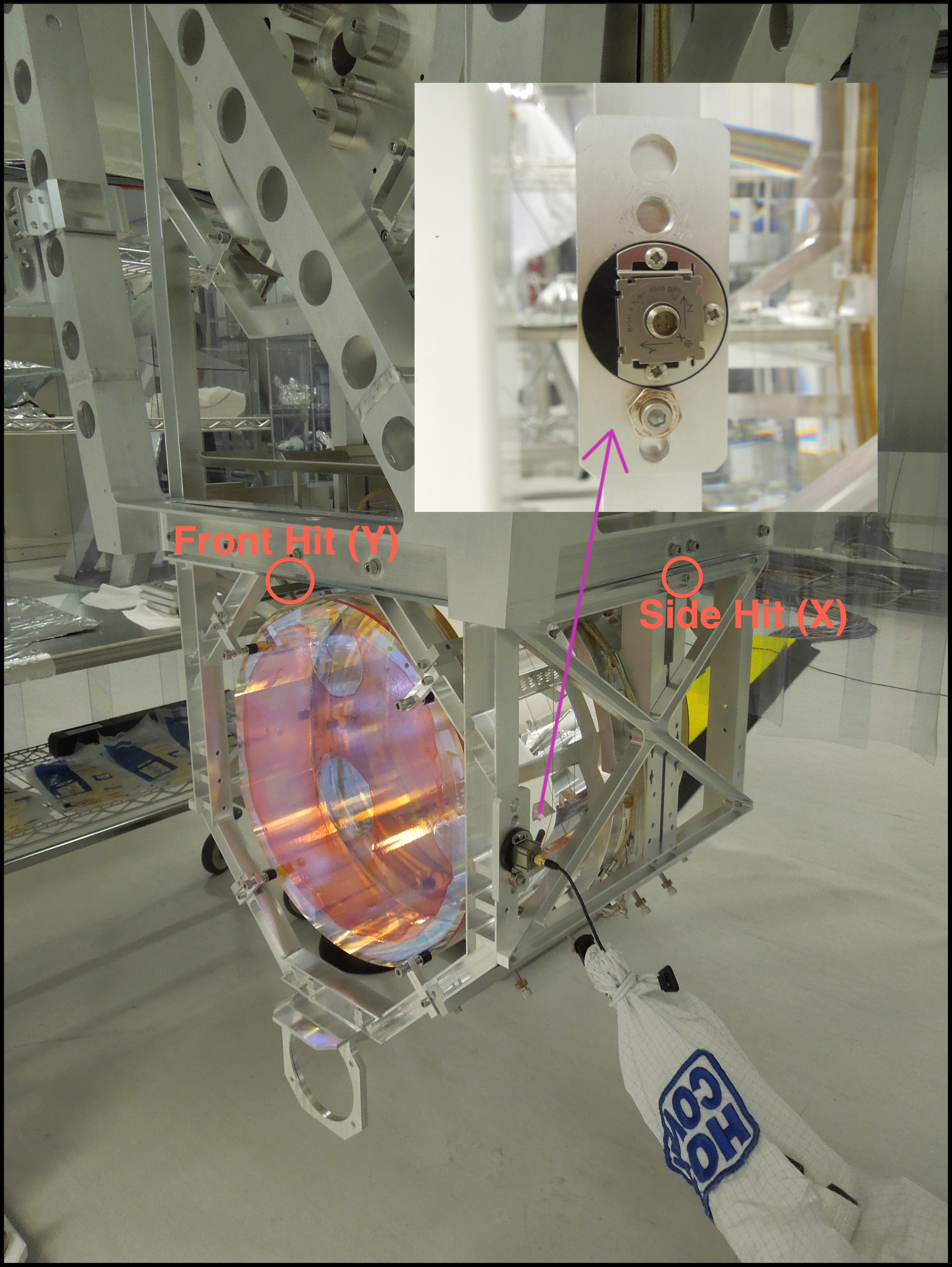
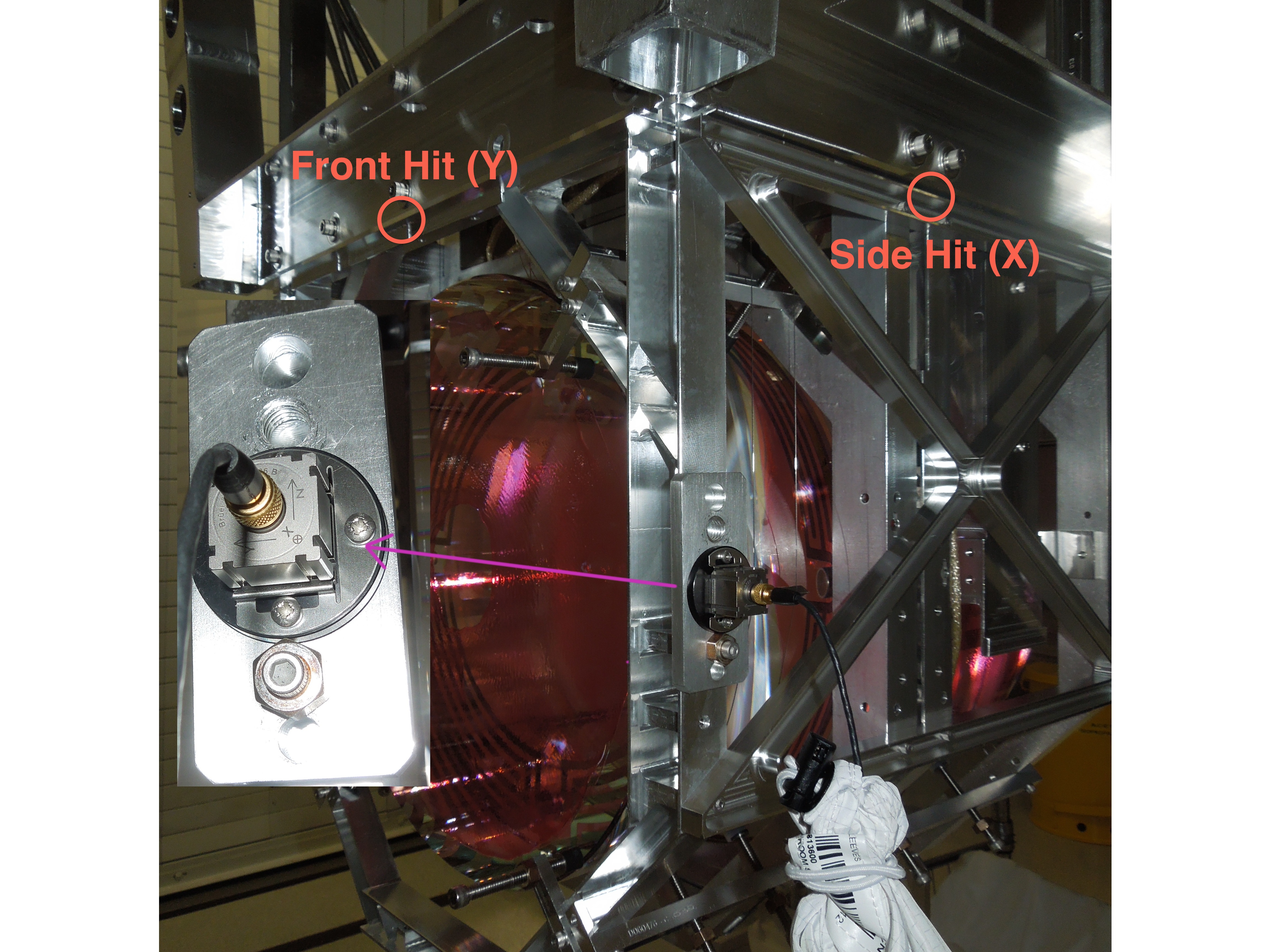
Over the past two days, B&K hammering measurements have been carried out on the ITMX and ETMX.
For the two measurements, the suspensions were fully payloaded, vibration absorbers were mounted on the structure, and the ISI was still locked.
A tri-axis accelerometer has been mounted on the corner of the structure, and the hit was given with a hammer at two different locations (front and side) as showed on the two pictures attached (1) for ITMX and (2) for ETMX. The pls template SimpleHammerDisplay3 from T1000697 was used to take the data, with a force threshold set at 10N.
Plots in "2013-09-13_H1ETMX_H1ITMX_ISI_Locked.pdf " are showing a comparison between the results for H1 ETMX, H1 ITMX, and L1 ITMY X resp to X exc on the 1st plot and Y resp to Y exc on the 2nd plot. The main resonnance below 150 Hz is well damped in both directions, for both suspensions.
----------
Data (ascii and pls files) are located in /QUAD/H1/${ETMX/ITMX}/BandK, plotting script (BandK_plot.m) is located in /Common/Matlabtools/, and pdf results are located in /Common/Data/BandK. They have been commited to the svn.
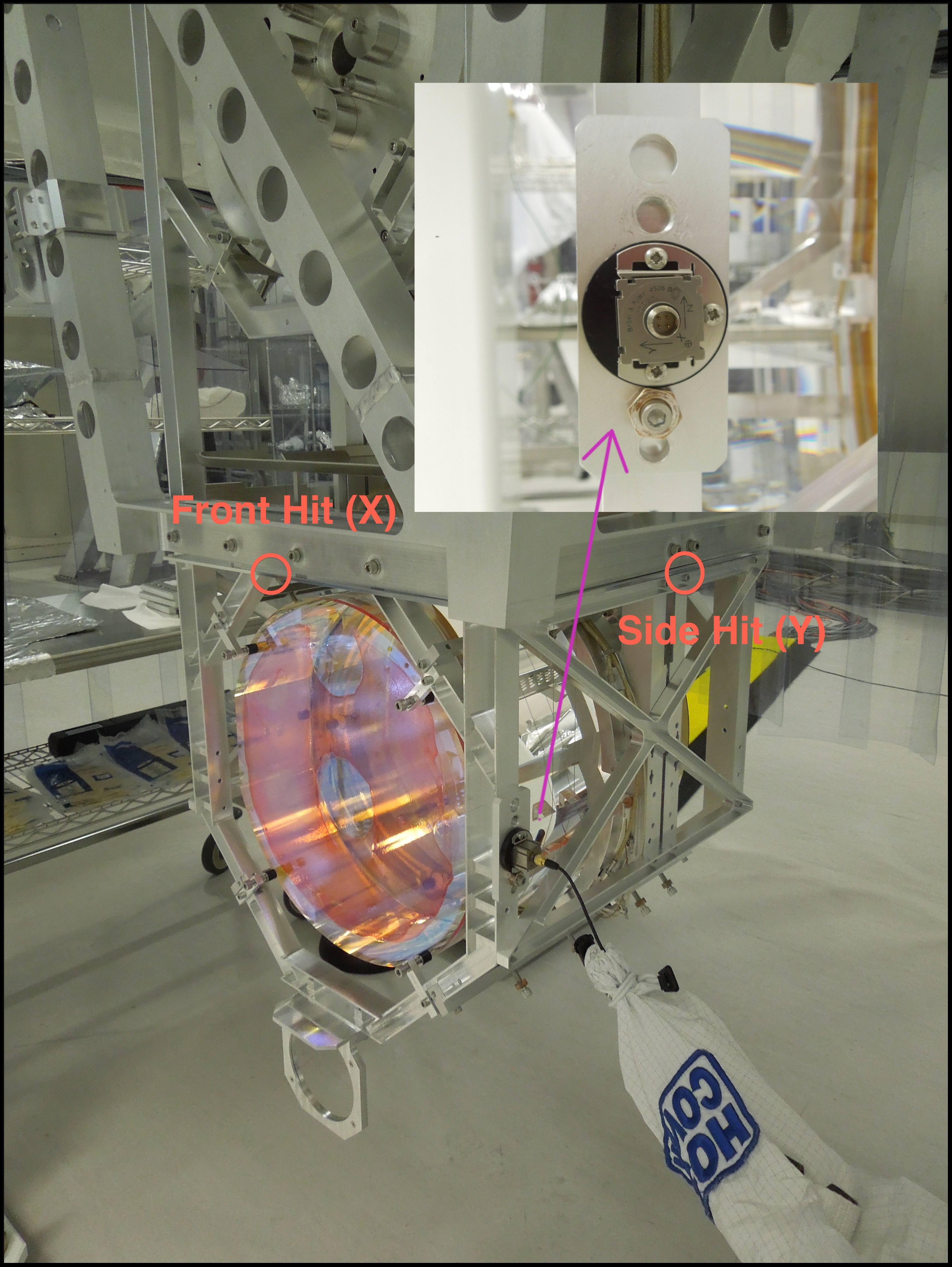
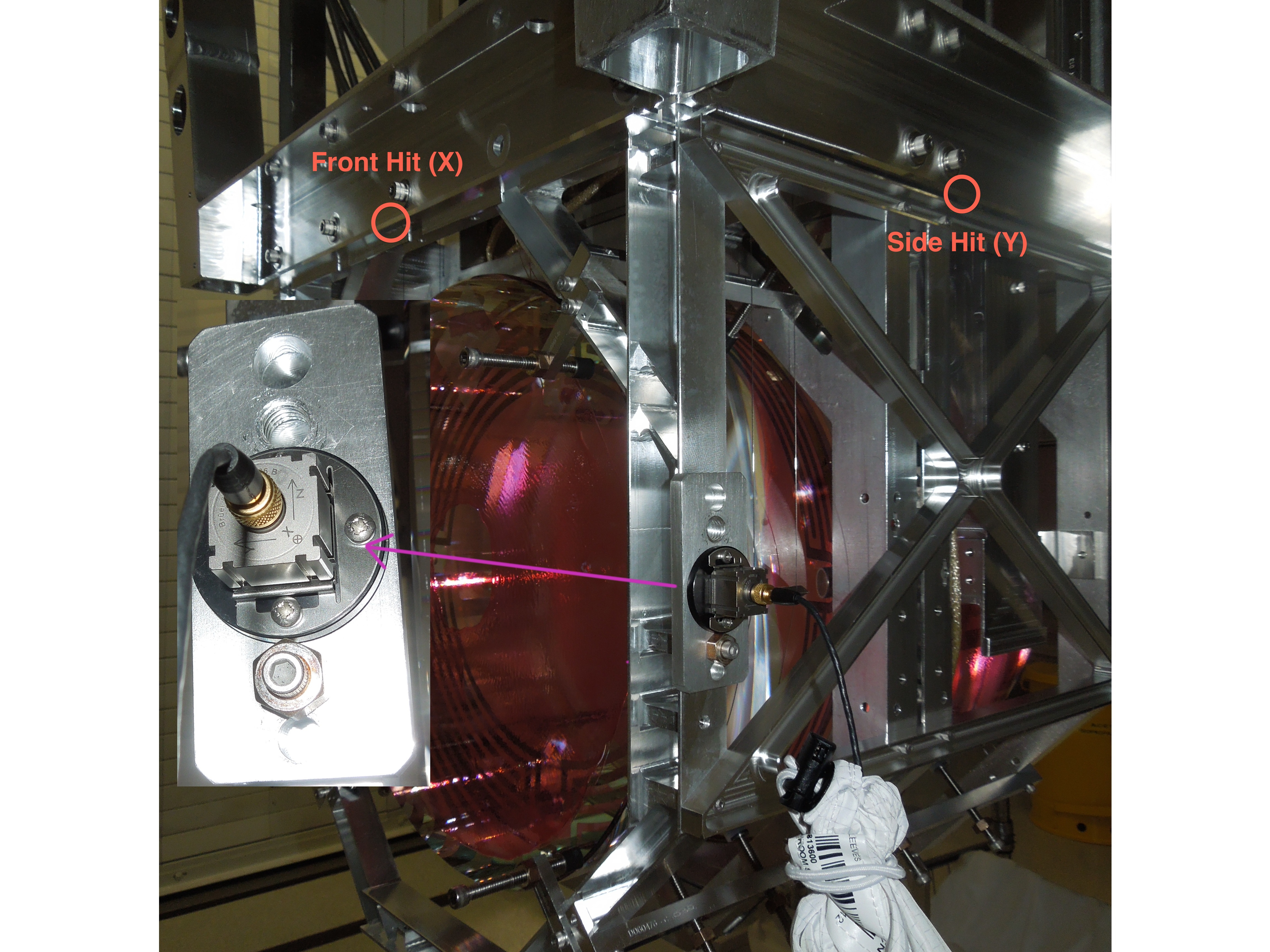
label of pictures above is wrong, since the hammer hit axis do not follow the accelerometer axis, I don't know how to delete them since I can't edit my aLog anymore.
The pictures attached to this comment are the references for the hammer hit direction
The sei test stand is now back on track and up to date with the last svn version (4455).
The front end IP address is 10.11.0.23 (seiteststand2). Two workstations are connected to the test stand network:
- stormy.ligo-wa.caltech.edu
- 10.11.0.94 --> use this station for the graphical display (especially on the Mac in the high bay)
The channel names for the test stand are ITMX channels (example: X1:ISI-ITMX_ST2_GS13INF_V3_IN1_DQ). Everytime we are testing a new unit, the result will be saved into the X1/ITMX/ arborescence.
*** Testing procedure for a new unit ***
Here's an overview of the different steps to do when a unit is tested.
1. Create the folder structure /X1/ITMX. You can either do it by hand or use the following function: /ligo/svncommon/SeiSVN/seismic/BSC-ISI/Common/Misc/Arborescence_BSC_ISI.m
2. Follow the document DCC#E1000486 to do the testing
3. When the testing is done and everything is saved into the good folders, rename the ITMX folder with the good name (ex: Unit_5). The different data are still going to be called with an ITMX name, but the overwall folder will have the good name. It will be enough for us to keep track of our units. The easier way to rename the ITMX folder is to use svn rename (ex: svn rename ITMX Unit_5)
4. Be sure to svn commit everything at the end.
5. Repeat the process for the next unit.
Day shift summary
08:00
LVEA Laser Safe
Alarms: Dust

09:39 Hugh at HAM6 working on HEPI
09:50 Cory & Andres at End-X working on face stops on ETM-X
10:06 Alexa working in HAM6/Squeezer bay – Bay is laser hazard
10:23 Cyrus Removing old network switch and relocating dust monitors
10:27 Gerardo & Tyler working on the ACB assembly at the LVEA SUS test stand
10:35 Andres working on cabling the SM HAMs
11:15 Instrument Air alarm on PT599 at End-X; Informed Kyle
13:47 Kyle in LVEA to shut GV2
13:57 Gerardo working on ACB assembly at the LVEA SUS test stand
16:00 Patrick recycling dust monitors in optics lab
ETMx Silica-tipped Earthquake Stops Positioned on Quad (Andres, Corey)
The face EQ stops for the ETMx needed to be positioned, but we don't want "glass on glass" contact. We didn't have thin teflon strips to insert between the EQ stops and the glass, so per Betsy's suggestion, we used Alpha Wipes as a buffer between the Stops & Glass.
SUS TMS Cable Fixed
Installed screws on an in-vac cable which had these screws missing from its connector. All TMS cables are good to go for dressing on the ISI.
Note, the above states that the face stops were adjusted to clamp the ETMx - from afar, I have clarified with Andres that indeed all of the appropriate barrel stops are actua;;y doing the clamping as I had prescribed for SEI balancing work.
