kiwamu.izumi@LIGO.ORG - posted 09:42, Tuesday 14 January 2014 - last comment - 09:43, Tuesday 14 January 2014(9257)
PSL work
Koji and I will be in the PSL today for replacing IO_MB_M2 as a preparation of the high power laser.
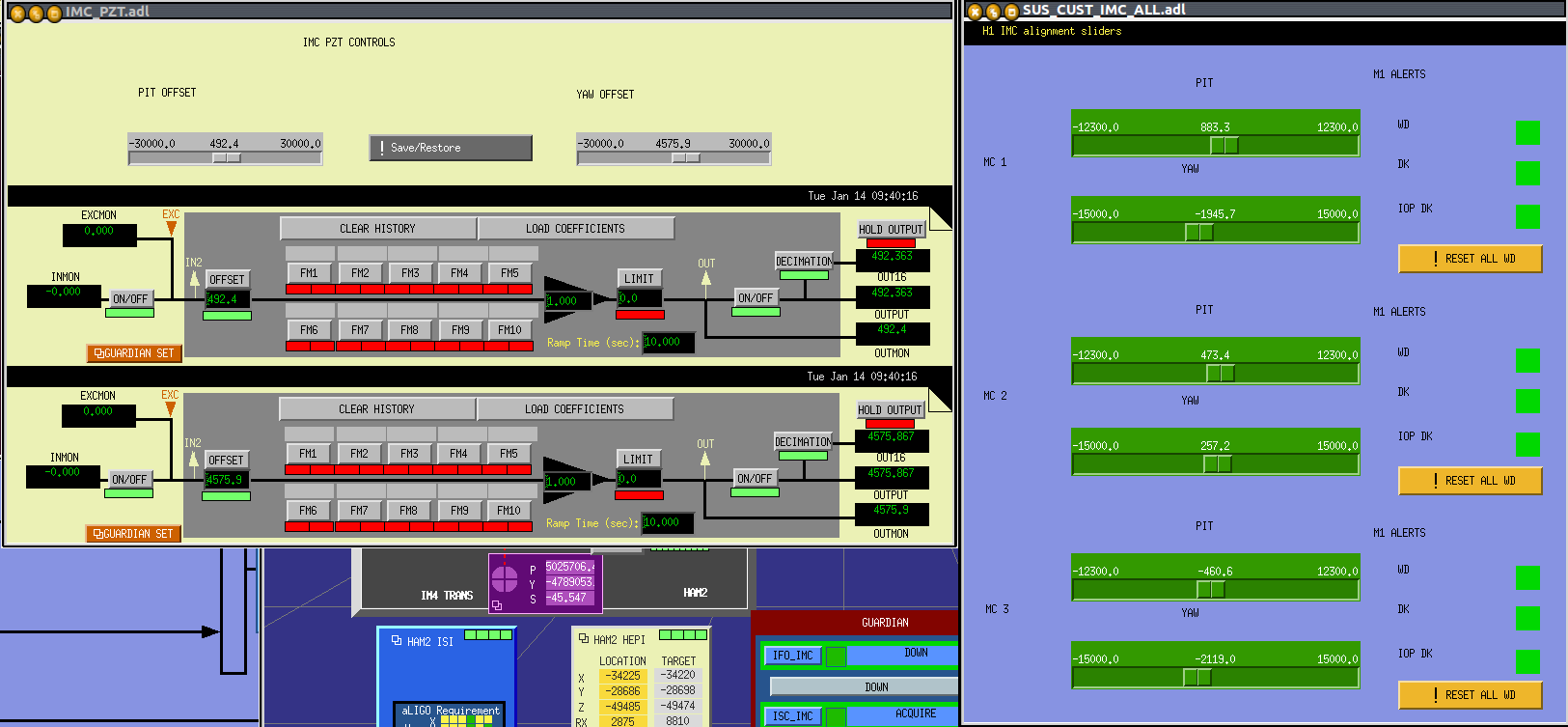
Please do not change the PSL piezo alingment and MC1/2/3 DC biases because they are our alignment references.
Images attached to this report
Comments related to this report
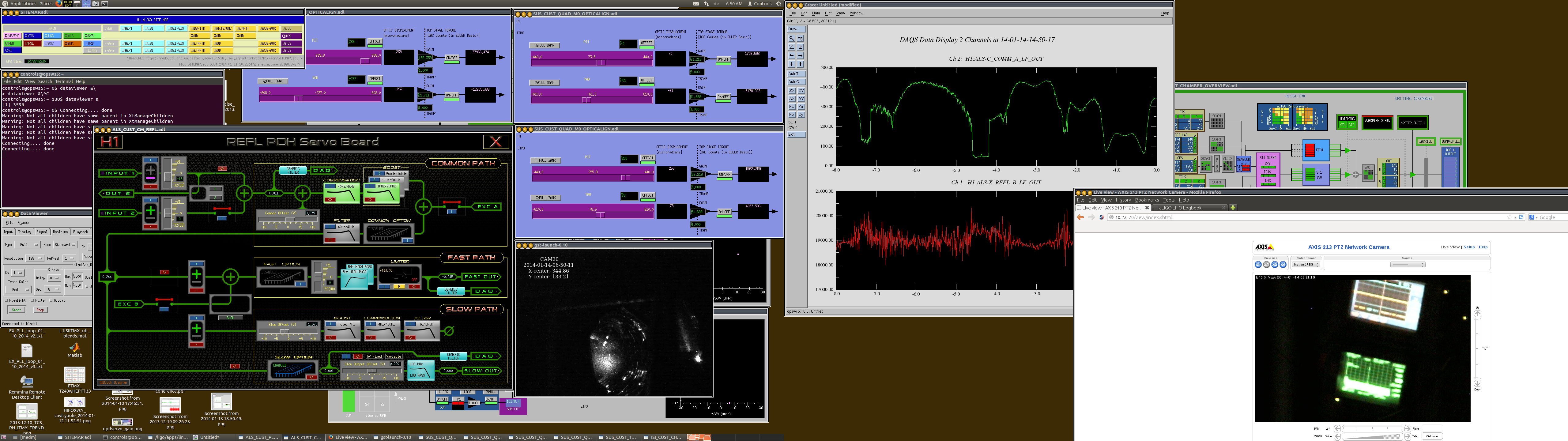
The attached was the current best alignment.


