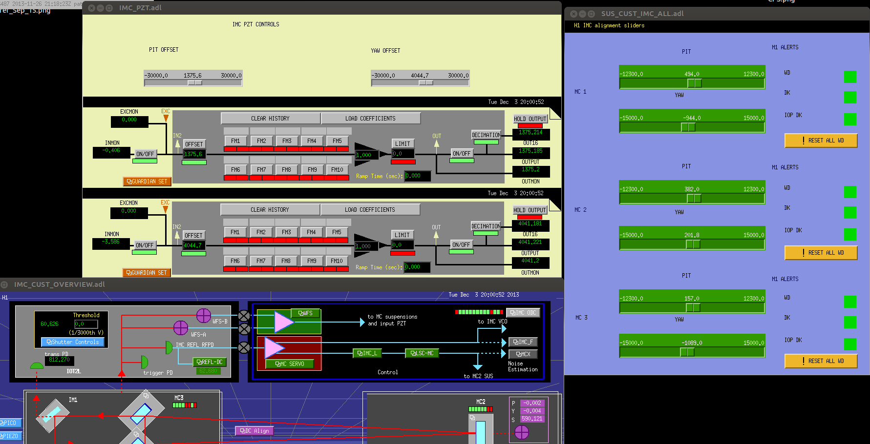
I turned the HEPAs, AC units, and make up air back to 100%. I increased the temperature of the AC units from 20 C to 21 C as this is the temperature the room seemed to settle at. We'll try another test in the future with this new setting to see how the room responds.
HAM2-HAM3 volume 9.1 x 10⁻⁷ torr before venting
With the help of Gerardo 1 and 2, and Deepak, we used the ergo arm to stuff the PR3 optic into the suspension. We then suspended the mass, adjusting roll and height to within the 1mm tolerance and 1mm. Official height numbers coming shortly. Deepak will tweek the top stage BOSEMs into center tomorrow and then we're ready for Phase 2b TFs.
LVEA laser safe all day. Ongoing H1 PSL enclosure environmental alarms all day relating to Robert Schofield's aLog entry from Sunday. Recall that HEPA and AC units are offline in the enclosure. Low differential pressure (LVEA<->PSL anteroom 0.00 inchesH20) and periodic high dust counts (briefly approached 1000 cts for 0.3 microns in the anteroom this morning, now at zero. No dust data for the laser room.) 0845-1000 - Paul F taking power spectra on IMC. 0845 - Doug D D working near H2 enclosure. 0900 - Corey G working around HAM6/Squeezer bay. 0910 - HFD onsite working on fire alarm systems in OSB and LSB, users should receive additional notification before alarms activated. 0930-1530 - Eric A and Chris (Apollo) in LVEA inspecting and working on valving and piping for HEPI systems. (HAM4/6 and BSC3). 1000-1500 - Gregorio to Pasco. 1000 - Apollo moving ERGO arm over beam tube to South Bay. 1030 - Filiberto running cables HAM1-HAM3. 1030 - Patrick and Justin reset remote dust alarm threshold for DST_16 to 1000cts (local alarm threshold unchanged). 1300 - First cleaning of HAM3-BSC2 spool. Justin to LVEA to investigate 80,000 ct (.3) dust alarm at DST_15. Vacuum cleaner had been running next to monitor. 1345 - Corey G to EY. 1430 - Keita pulling a length diode on IOT2L (H1 PSL shutter is closed). 1545 - Justin reset remote alarm threshold for DST_16 to default values (minor>100, major>200).
I turned off the LSC RFPD interface chassis (D1102060) for IMC length diode using the switch at the back panel, disconnected the length diode cable, connected a DB9 break out board at the front panel without connecting anything else (but the back panel was still connected to the ADC), switched on/off the chassis (again using the switch at the back) and measured how the +-18V supply for the diodes behave.
To my disappointment, every time I did this test, for about 1ms to 1.5ms there was a window where the negative power was -18V but the positive was basically non-existent (below 5V). It seems as if the negative voltage goes live immediately. See the first picture, the scale is 5V and 1ms/div.
This is the unit that we've been using since the start of IMC installation.
I did the same test for WFS interface (D1101865), and it was only marginally better than the length interface (second picture, same scale as the first one).
This is the unit that replaced the broken unit, but since this one was put into service WFS was connected/disconnected hot.
Switching off was much better for both of these units, basically both of the rails came down slowly at the same time (the last picture, note the slower 4ms/div scale).
During these tests, the only things powered by the chassis were the DC interface cards in the chassis and of course the power protection board itself.
I don't know if the units are broken, we'll test them further though the change Rich Abbott made to diode boxes will hopefully make this behavior harmless.
These are taken with the HEPAs in the anteroom and laser room off, with the make up air fan turned to 30%. AC units are off as well.
We flew the ergo arm to the south bay for Betsy. Disassembled the E module and moved to the north side of ham 4, started disassembly of the work platform that was around bsc 1 for install at bsc 2. Need to remove (with approval granted from Hugh) the horizontal hepi accuators on the south side of bsc 3 to allow installation of the work platform section between bsc 2 & 3. These will be unbolted and rolled down will still being secured with the current hepi bolts. (This same thing was done on bsc 2 for some clearance issues.) Also assisted Hugh/Eric with hepi install.
A month ago when we restarted the laser we noticed the frontend power monitor was reading only 6W. This was tracked down to a gain setting that was modified and not entered into the safe.snap file, so when we rebooted the computer frontends for the 2.6 code upgrade the incorrect gain value was entered. I've changed back to the correct setting and updated the safe.snap file, and we are now reading 31W.
[Kiwamu, Paul]
Just before the vent today we measured new noise spectra for the frequency and length feedback paths.
The 'whitening filters' in the IMC_X path (see Giacomo's LHO alog entry 5311) were not engaged. They were put in the model at LLO in an attempt to combat the digital noise in IMC_X above ~50Hz (see Anamaria's LLO alog entry 5821) but need to be taken account of when plotting the data.
We corrected the IMC_F frequency to length calibration to give the equivalent motion of MC2, instead of the equivalent round trip length change. This has now been edited in the filter bank for the IMC_X path; the FtoL filter has been changed to a DC gain of 5.8465e-14 (dX=df x lambda/(2FSR)).
Relevant paramters during the measurement:
Common mode gain 20dB
Common mode filters: Compensation and 1st Boost
Fast gain -2dB
Slow path bypassed offsets and filters
MC2 M3 lock gain -1000, engaged filters: 150:4 and CLP100
MC2 M2 lock gain 0.06, engaged filters: 0.01:0.1, 0.03:1, Stab8:2, 300:1 and ELF80
Damping filter: resg and Ellip50 (the filter in IMC_X path was switched to the wresg filter to reflect this change)
Jeff quite rightly pointed out that there are actually 2 more filter banks in the length path for the IMC which I didn't mention in the above post.
One of these is the H1:IMC_L bank, with the following 3 filters engaged and with Gain=1: antiWhite, roll3notch and bouncenotch.
The other bank is the H1:LSC-IMC bank, with 1 blank filter engaged with Gain=1. I'm not sure yet what the purpose of this bank is but would happy to know if someone else does! I'll try to get a signal flow chart up here soon, though it may be a little trickier from off-site.
I was revisiting this measurement and I thought it might be useful to add the PSL frequency noise requirement line for comparison (see attached).
The FMCS IOC needed a restart, presumably due to the failure of /ligo on Sat morning.
I burtrestored it to 2013/02/01/00:00.
I shut down the HEPAs in the ante room and in the laser room, shut down the 2 ACs (though I could not see their effect, so they could be left on) and set the makeup air at 30%. Overnight the temperature on the table increased by a couple to several degrees. The IMC was still locking, though very poorly. Paul tuned up the alignment of the IMC and the REFL_DC level returned to better than it had before the change (about 50 counts). The figure shows a comparison of IMC_F and the accelerometer at the top of the periscope in the two modes.
How much overpressure is in the PSL laser room when you run the makeup air at 30%? Do you see an effect from the makeup air at different speed? When I reduced it at LLO I did not see any difference in MC_F.
I saw 0.013" of water overpressure from the laser room to ante room.
[Adam M., Paul]
The IMC Guardian script can now be used to maintain the required state of the IMC.
This was achieved using the essentially the same scripts as in Livingston, but with some temporary local modifcations to account for the difference in the install state at the two sites (for example, ASC loops are not controlled by the guardian at LHO yet). The current state should be regarded as temporary, and if it's not required one can still of course lock the modecleaner in the way we have been doing up to now. (However, it may be useful for commissioning as we have already experienced the frustration of wondering where our signals have gone before realising the IMC was unlocked). The scripts can be found in /opt/rtcds/userapps/release/ioo/h1/scripts/imc
Some details:
Since we don't yet have a beam on MC2 trans QPD, we are using the MC_REFL_DC_OUTMON channel to verify the locked/unlocked state of the IMC. Currently, the threshold is set to 70 counts, because when aligned reasonably well the REFL_DC count is around 45. If the alignment state changes significantly, for example due to the change in PSL temperature or the upcoming vent, I recommend to lock manually first and realign to bring the locked REFL_DC counts back below 50 or so. If necessary, as an alternative the threshold can be changed in the imc_params.txt file. Of course if the laser power is changed significantly, the threshold should be adjusted.
The starting common mode gain is 0dB, which ramps up to 16dB upon lock acquisition. If there are problems to do with locking to bad modes, it may be necessary to reduce the starting gain. This can be edited on line 44 of the mcdown script. The locked gain can be edited on line 20 of the mcup script. Currently it takes two steps of 8dB from 0dB. If the starting gain is edited, this should also therefore be edited, or it could be rewritten to just make one step to the required gain.
Commencing Matlab TFs on PRM.
TFs completed apparently successfully by about 10:30 am Sunday 2/9: Undamped: ^/trunk/HSTS/H1/PRM/SAGM1/Data/2013-02-09-1044516432_H1SUSPRM_M1_0p01to50Hz_tf.mat Damped: ^/trunk/HSTS/H1/PRM/SAGM1/Data/2013-02-10-1044536209_H1SUSPRM_M1_0p01to50Hz_tf.mat Plots pending.
Totally pristine plots.
Viton pads are usually set under the balancing masses of the HAM-ISIs in order to damp resonances at high frequencies (above 100Hz).
The SEI team would like to asses the improvements that the Viton Pads help achieving. To do so, we decided to have viton pads under the balancing masses of the ISIs of LLO's IMC, and to try without those pads here at LHO.
Transfer functions were measured ovenight on LHO HAM3-ISI. We compared those transfer functions with the ones measured at LLO under an equivalent state:
Comparative plots are attached.
The script which produced the plots mentioned above was re-checked. The curves it displays match with the ouput of the generic commissioning scripts, for both LLO and LHO.
Data in the 5Hz-200Hz range was retreived and added to the plot. Results are attached.
The results presented above were calibrated and transposed into the cartesian Basis, as performed during the step 3 of the commissioning process of HAM-ISIs.
Narrow peaks can still be seen on LLO's transfer functions. We held off on the installation of the Scraper Baffles here, while they were already on the ISI at LLO, at the time of the measurement. It could be the cause of it.
Once HAM3 chamber is open, we will look at the items installed on the ISI. It should help clarifying the cause those peaks that we did not witness here.
I attached a picture of HAM3 chamber taken on Dec 6th 2012. Pumpdown started on Dec. 21st.
We measured the diameter of the optic to be 265.1mm, while the vendor data posted on the CIT Nebula website shows 264.91 so we're in pretty good agreement. We tweeked the height of the optic via adding 20g of mass to the top of the top mass, setting the bottom of the optic 26.6mm from the table surface. This sets the center line of the optic at 158.75mm off of the table surface. Nominal is 158mm as per the optomech layout drawing for PR3 on HAM2.