Here is the current status of the aLIGO SEI work at Hanford. The main updates of this week are:
- ITMX, HAM2 and HAM3 have been tested (chambers are closed)
- HEPI generic and local models have been updated, installed and tested
· BSC1 - ITMY
o ISI + HEPI - Unlocked, Previously commissioned.
· BSC2 - BS
o ISI + HEPI - Unlocked, Previously commissioned.
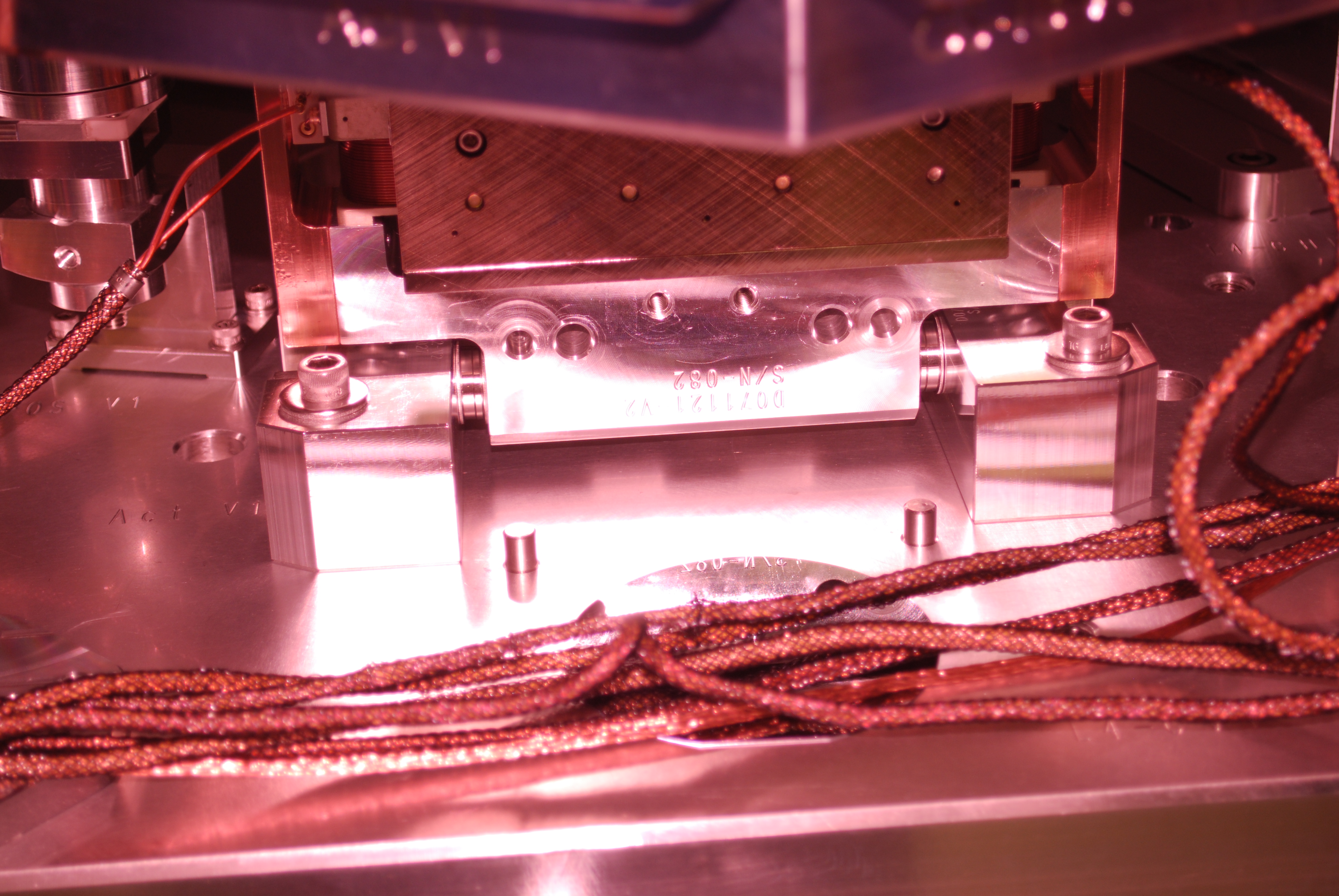
· BSC3 - ITMX
o ISI : Testing complete, in chamber. Report validated.
o HEPI : Unlocked.
· BSC9 - ETMX
o ISI : Unlocked. Testing complete.
o HEPI : Unlocked, ongoing initial alignment.
· BSC10 - ETMY
o ISI : Currently installed in BSC6. Will be pulled out and installed in BSC10. Payload (SUS) will be moved then. Electronics are disconnected
o HEPI : Unlocked.
HAM 1
o HEPI: Locked and vented.
Low priority testing
· HAM2
o ISI: previously commissioned with HEPI locked, currently unlocked, in vacuum
o HEPI - IPS position loops and alignment offsets installed
Locked
· HAM 3
o ISI: previously commissioned with HEPI locked, currently unlocked, in vacuum
o HEPI - IPS position loops and alignment offsets installed
Unlocked
· HAM 4
o ISI: In chamber, Previously tested during assembly validation, currently locked, no suspension installed, in-vac cables not connected.
Electronics ready, in field cables ready, in-rack cables ready. Temporary STS cables
Model is running, and MEDM screens are available in the Sitemap.
o HEPI: Currently locked, to be commissioned
Electronics ready, in field cables ready, in-rack cables ready. Temporary STS cables
Model is running, and MEDM screens are available in the Sitemap.
· HAM 5
o ISI: In Chamber, Previously tested during assembly validation, currently locked, no suspension installed, in-vac cables not connected,
Chamber temporarily closed.
Electronics ready, in field cables ready, in-rack cables ready. Temporary STS cables
Model is running, and MEDM screens are available in the Sitemap.
o HEPI: Currently locked, to be commissioned
Electronics ready, in field cables ready, in-rack cables ready. Temporary STS cables
Model is running, and MEDM screens are available in the Sitemap.
· HAM 6
o ISI:
in chamber.
Unlocked, no SUS
Mechanical adjustments complete
Initial in-chamber testing complete, but not validated yet
o HEPI: Locked
Happy thanksgiving everybody

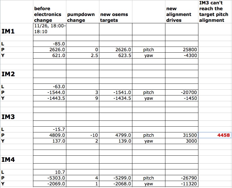


These are the HAM-A Drivers for the HAUX;
Optic Name       Name on Drawing*       Rack Location      Chassis Serial Number
    IM1                SM1                C4 - U14                S1201156
    IM2               PMMT1               C4 - U8                 S1201162
    IM3               PMMT2               C4 - U7                 S1201155
    IM4                SM2                C4 - U13                S1201165

* aLIGO SUS HAM2 System Wiring Diagrams, Current Version, D0902810-v7

This means that the output impedance for these drivers is significantly less that before, which means both the noise and the drive strength have decreased by a factor of a factor of 10 (calculation below). This explains why we need much more drive from the IM's DAC in order to retain the same alignment offsets (see LHO aLOG 8759), and as Cheryl mentions, in some cases (IM3), the DAC saturates before we can get to the desired alignment offset. So, we either need to physically offload the alignment on the SUS themselves or reduce the output resistors enough to be able to both obtain the desired alignment while still meeting the noise reduction goal.

(Icoil / Vin)_after      (Vin/Vout)_after / (Rcoil + 2*Rout_after )
-------------        =   -----------------------------------------
(Icoil / Vin)_before    (Vin/Vout)_before / (Rcoil + 2*Rout_before )

                        (Rcoil + 2*Rout_before)
                     =  ------------------------
                        (Rcoil + 2*Rout_after)

                        (Rcoil.aosem = 19.8 [Ohm] [see LLO aLOG 3340])
                        (Rout_before = 100 [Ohm])
                        (Rout_after  = 1200 [Ohm]

(Icoil / Vin)_after
-------------        =  0.098
(Icoil / Vin)_before