Kiwamu, Sheila
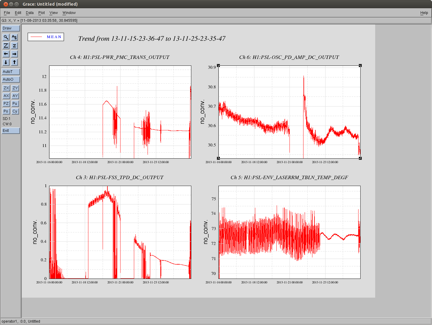
After the transition to science mode on friday the temperature in the PSL enclosure has stabilized, now the daily fluctuations are about 1 degree F and the 20 min oscillations are completely gone (bottom right of attached screen shot). The laser power (top right) is slightly more stable, and 20 minute oscilations in the ref cav trans are completely gone (lower left).
We will stay in science mode unless someone is actively inside the PSL.
Kiwamu and I went in this morning (we transitioned to commisioning mode first) with three goals: Kiwamu wanted to investigate the status of the rotation stage, to try to reduce the comination of the PMC trans camera with light from the reference cavity, and to search for reasons for the ref cav misalignment/ fix it.
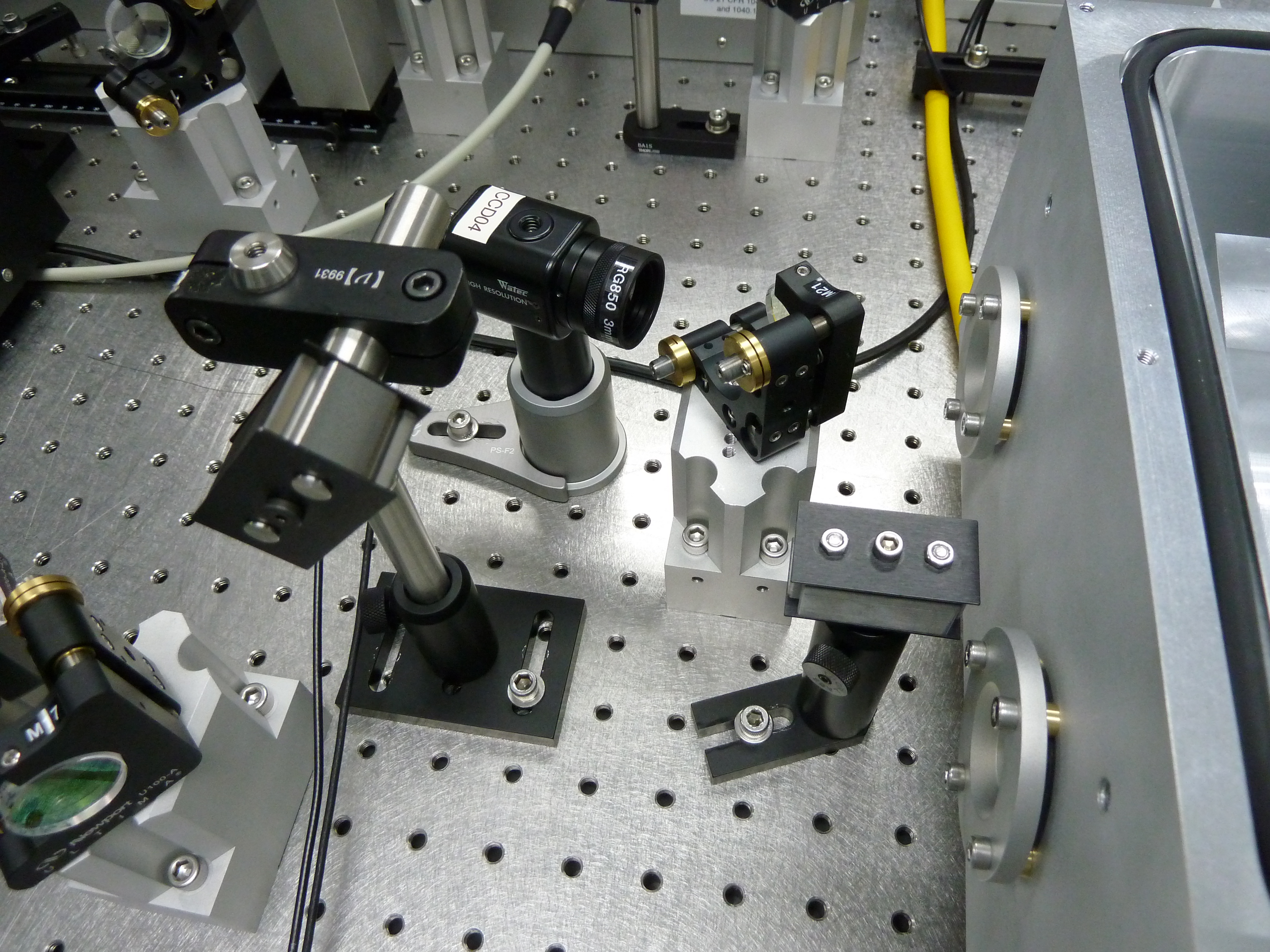
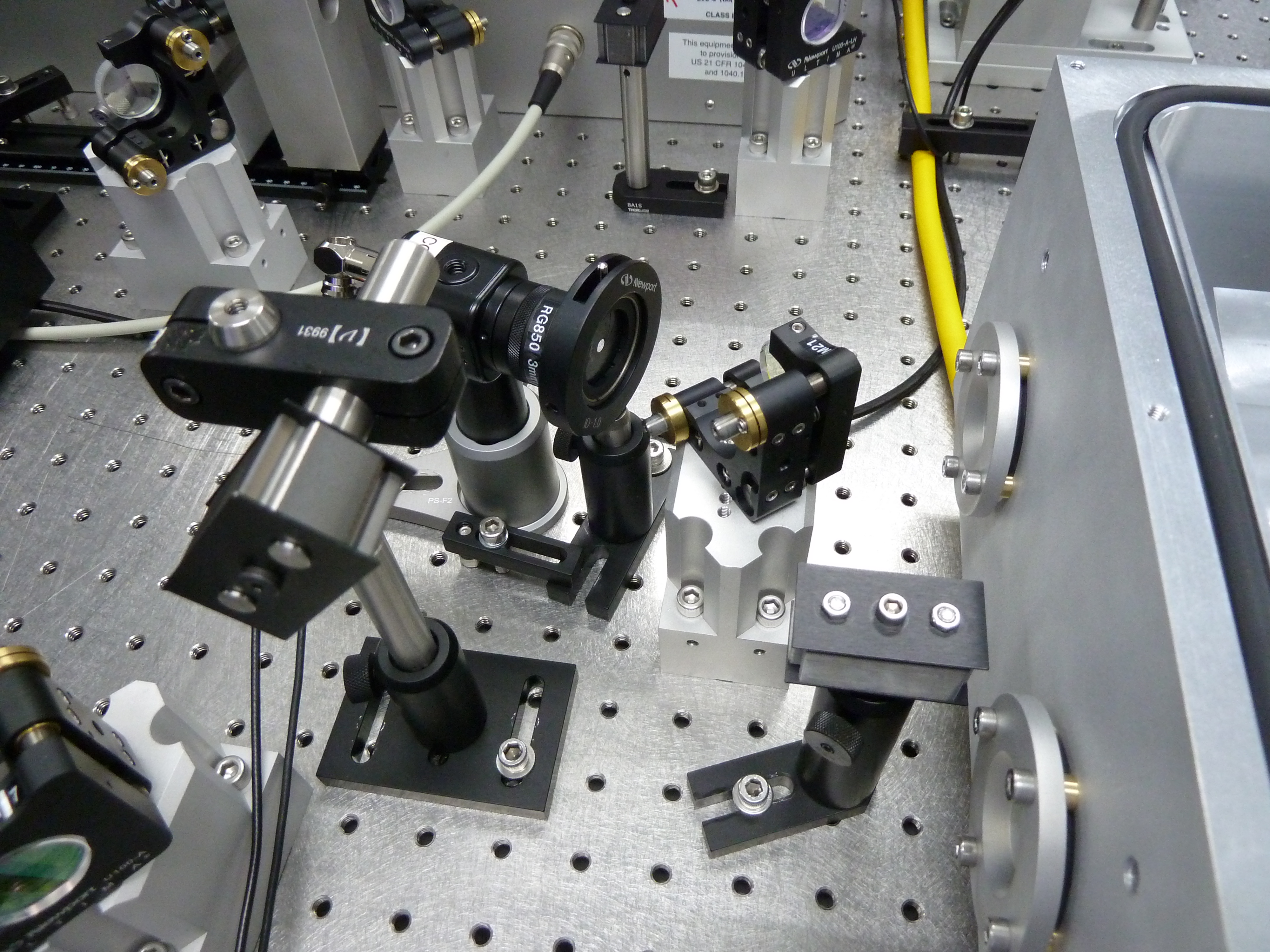
The image on the PMC trans camera is clearly different when the ref cav is locked and when it is not. We confirmed that this is not due to a stray beam coming at a large angle but something that travels almost along the same direction as the PMC trans beam. There is also a large "smudge" in the image. We found that by blocking the power meter on the PMC refl port we got rid of the smudge. TIlting the power meter slightly did not move the smudge position on the trans camer at all, although it did seem to reduce the amount of power in it. It seems as though this is light that is scattered into the PMC reverse propagating mode from the power meter, and then clips somewhere on the way to the trans camera.
We also seem to have light from the reference cavity in this "smudge". This could be because the reference cavity circulator is slightly off, and some of the reflected light gets back into the PMC in the counter propagating mode. We did not try to adjust the quater wave plate, but it is possible that could help.
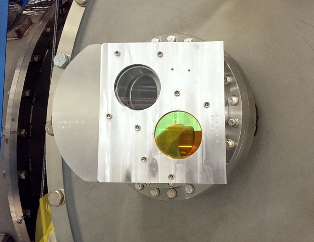
In the end we added an iris before the PMC trans camera, there is still a difference between the on screen image with and without the reference cavity locked, but it is much better and the centroid position calculated by Chris's script is almost the same when the ref cav is locked and unlocked. A picture of the camera before and after the iris was added is attached. For future reference, on the PMC trans camera up on the table looks like down on the camera, and vice versa.
We then moved on to looking into the ref cav alignment. We tried taping and pushing gently on the optics in the path from the PMC to the ref cav, nothing was obviously loose and the alignment always returned to where it was when we took our hands off. We noticed that the beam shape after the EOM was bad, and when we looked at the aperatures on the EOM the beam seemed high. We brought the EOM up, which improved the beam quality. When we were done adjusting the EOM we had (with the ISS disabled) 12.9mW incident on the EOM and 12.6mW after. This clearly misaligned the reference cavity, we recovered the alignment using the camera and the iris at the front of the cavity as references, and adjusting the top periscope mirror and M27 in pitch. We were able to get back to about 0.6V on the transmitted PD by walking the beam once the cavity was locked. We expected to be able to get more than 0.9V, so something is still amiss. Also, the spot position on the reflected camera has moved. This does not make sense because there is no reason the reference cavity position should have moved (we think) and the beam is aligned to the cavity. When the cavity is locked we see bassically nothing in reflection right now, and the spot position on the trans camera down't appear to have moved much.
We then realigned the ref cav reflection PD, using the DC power on a scope. Kiwamu noticed that the value on the MEDM screens for the refl DC was not changing while I did this. It seems as though the input is grounded in the model, he is looking into how we can get this recorded in the digital system.
The EOM misalignment could have been a symptom or a cause of the problems we have been having. We decided to leave things be for now, and have a look at trends over thanksgiving when no one should be going into the PSL and the PSL is in science mode.