- Filiberto and Frank to EY for electronics verification
- Jeff and Thomas to BSC3 to work on ACB
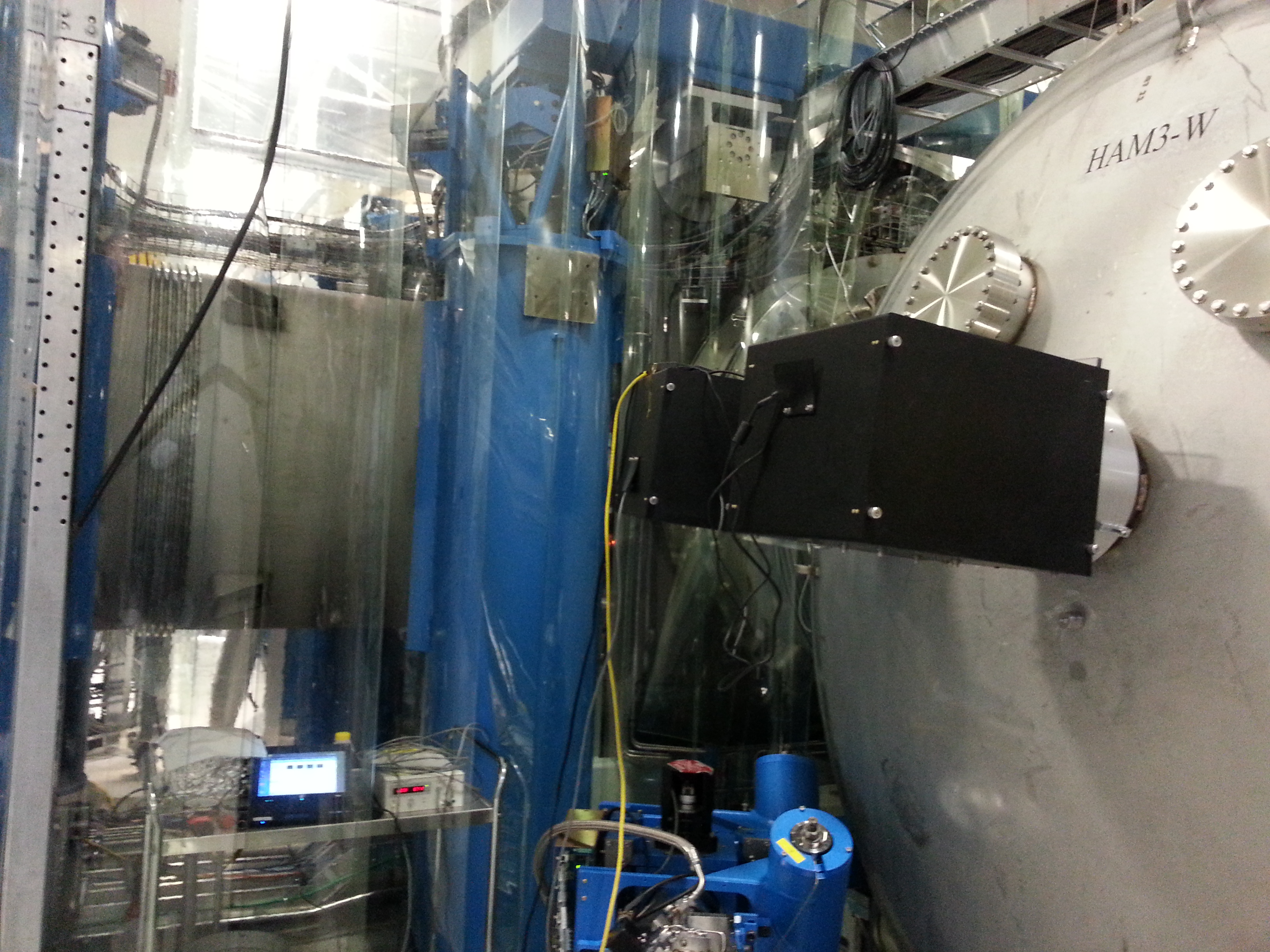
- Bubba/Apollo to install viewports on HAM3
- Jodi and ? to EY to vacuum out bellows/beam tube where spool was removed
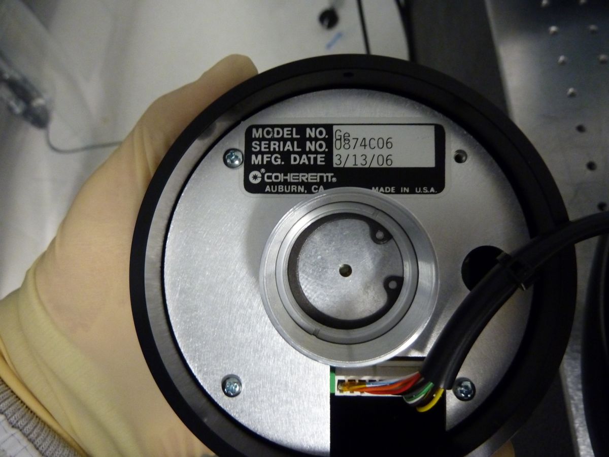
- Joe and Greg - laser hazard in H2 PSL enclosure for alignment work
- Sheila - transitioned EX to laser safe
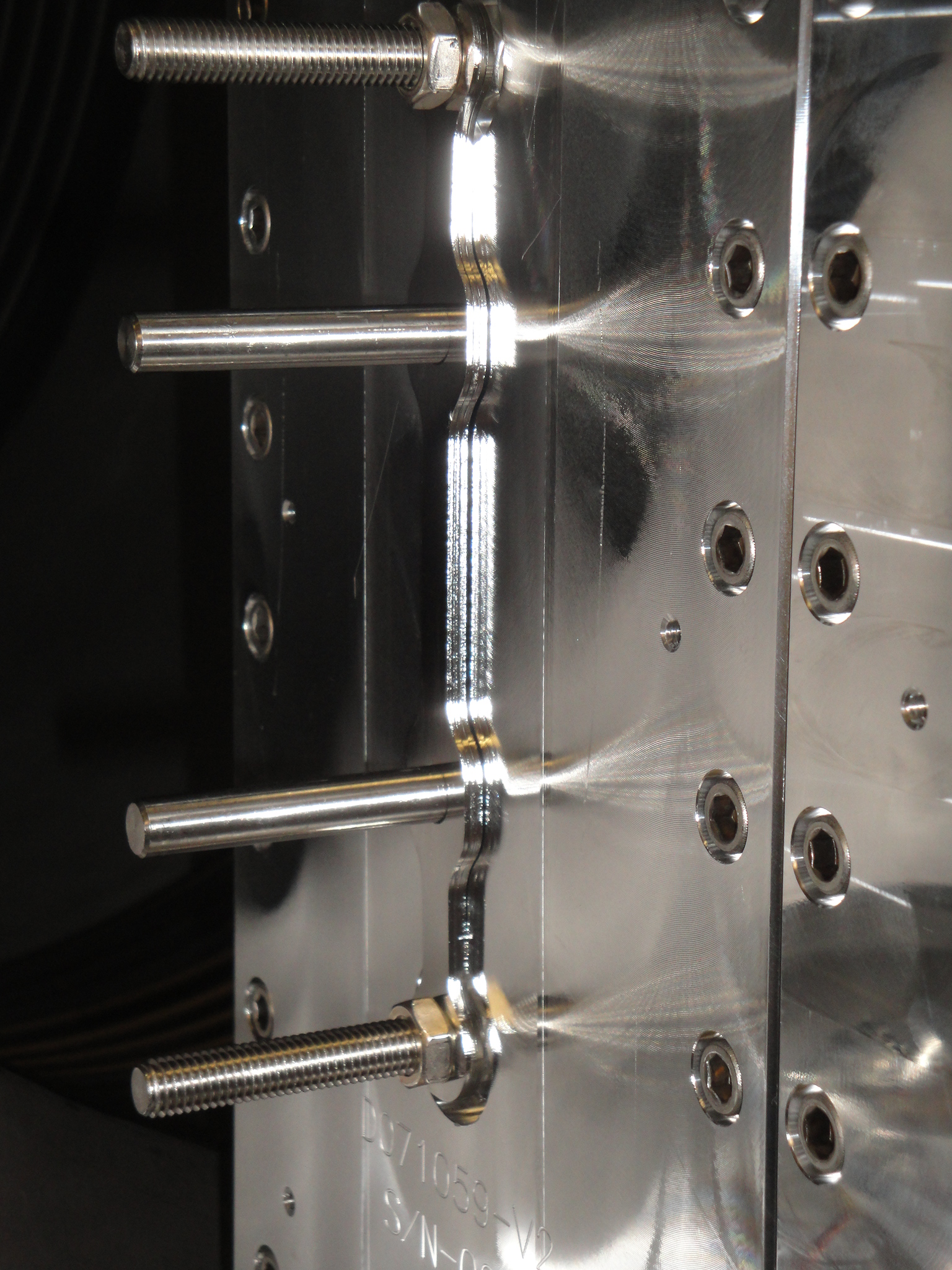
- Jeff and Andres to EX to remove pushers (in chamber work)
- around noon, starting to put HAM2 doors on
- Jeff and Andres back out to EX after lunch and talks
- HAM2 doors are on
- Reverse Osmosis alarm around 3PM
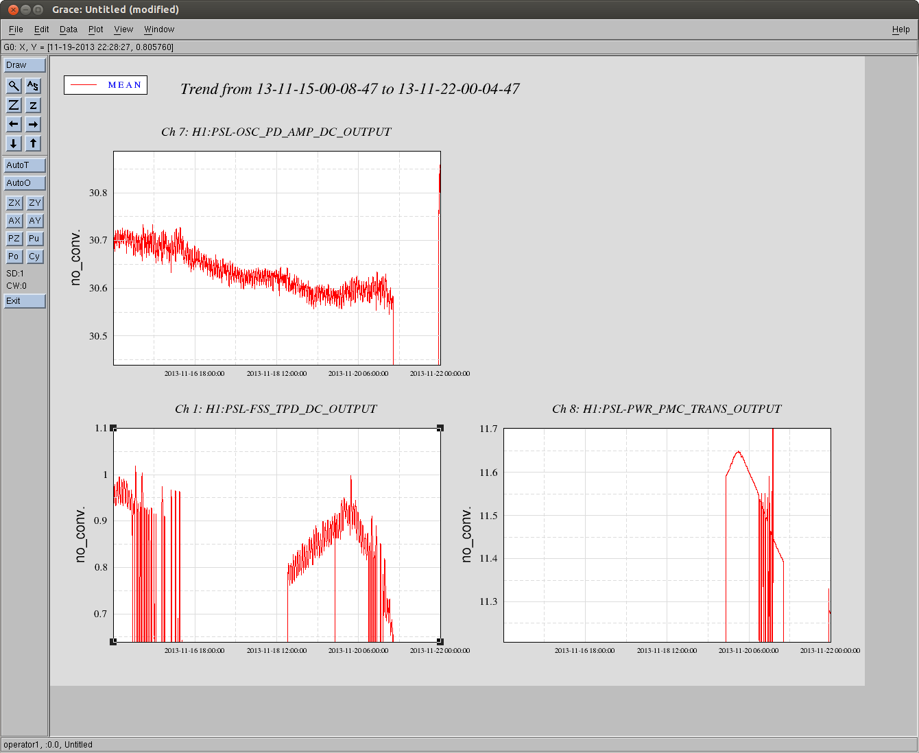
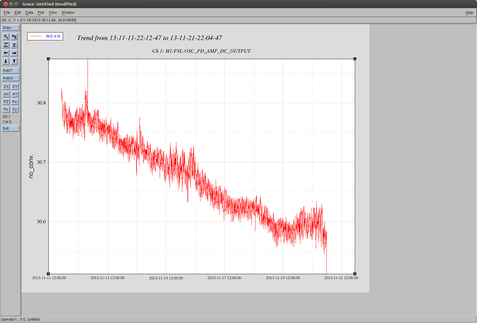
- Sheila restarted the H1 PSL laser
- I redamped HAM2 and HAM3 optics